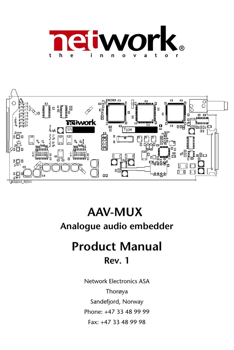
Network Electronics Flashlink AAV-DMUX User manual

AAV-DMUX Rev. 1
User Manual
AAV-DMUX (-R)
Analogue audio de-embedder
Network Electronics ASA
Thorøya
Sandefjord, Norway
Phone: +47 33 48 99 99
Fax: +47 33 48 99 98
e-mail: su[email protected]
www.network-electronics.com
Direct Service Phone: +47 9060 9999
1

AAV-DMUX Rev. 1
1 Revision history
The latest version is always available in pdf-format on our web-site:
http://www.network-electronics.com/
Current revision of this document is the uppermost in the table below.
Revision Replaces Date Change Description
1 0 2005-10-21 Style, gain switch examples and group switch names in
table corrected.
0 C 2005-05-27 GPI specifications, GPI pinning, layout.
C B 2003-3-1 Optical input specification
B A 2003-11-17 Gain table for first production series.
A Preliminary version. Pre production run.
2

AAV-DMUX Rev. 1
Index
1 REVISION HISTORY.................................................................................................2
2 INTRODUCTION.....................................................................................................4
3 SPECIFICATION......................................................................................................4
3.1 Measurement conditions...................................................................................4
3.2 General.............................................................................................................5
3.3 Inputs................................................................................................................5
3.3.1 Video Input:..................................................................................................5
3.3.2 Optical Input:................................................................................................5
3.4 Outputs.............................................................................................................5
3.4.1 SDI Output ..................................................................................................5
3.4.2 Audio Outputs:.............................................................................................6
3.4.3 GPI................................................................................................................6
4 DETAILED DESCRIPTION.........................................................................................6
5 CONFIGURATION...................................................................................................7
5.1 DIP switches......................................................................................................7
5.1.1 Output gain..................................................................................................7
5.1.2 No EDH insert...............................................................................................7
5.1.3 Remove audio...............................................................................................8
5.1.4 Group Selection............................................................................................8
5.1.5 Monitoring the status with Gyda..................................................................8
6 LIMITATIONS..........................................................................................................9
7 CONNECTOR MODULES........................................................................................9
7.1 GPI Control Connections................................................................................10
8 MODULE STATUS.................................................................................................11
8.1 LED Overview..................................................................................................11
9 LASER SAFETY PRECAUTIONS...............................................................................12
10 DECLARATION OF CONFORMITY WITH CE........................................................12
11 ENVIRONMENTAL REQUIREMENTS FOR NETWORK FLASHLINK® EQUIPMENT .13
3

AAV-DMUX Rev. 1
2 Introduction
The AAV-DMUX card is an analogue audio de-embedder card for serial digital video
for four audio channels. It is one of the Flashlink series of modules, providing a
compact and cost effective solution for the transport of digital video and audio over
single mode optical fibre.
The card has a serial digital video input and a serial digital video output. There is an
optional optical input which will be used automatically if an optical signal is present.
When the optical option is present, the card switches automatically between the two
inputs looking for a valid signal. The first valid signal found will be used until lock is
lost, then the other input will be tried etc. This makes redundant fibre feeds easy to
implement with just an extra SDI-OE card.
The optical receiver is compatible with both single and multi-mode optical fibre and
may be used as a receiver in point to point, CWDM and DWDM configurations.
The analogue audio outputs can be configured for different output levels. The
maximum level can be set to levels between +12 dBu and +24 dBu. All audio outputs
have independent outputs which are electronically balanced.
Figure 1 AAV-DMUX Block diagram
3 Specification
3.1 Measurement conditions
Sampling rate 48 kHz
Ambient temperature 25ºC
Measurement bandwidth 20 Hz-20 kHz
Detector RMS
Input overload level (0 dBFS) +18 dBu
4
Serialiser
Reclocker
deserialiser EmbedderSDI
Audio1L
Audio1R
Audio2L
Audio2R
SDI
Optical
input

AAV-DMUX Rev. 1
3.2 General
Power: +5V 480mA 2.4W, +15V 100mA 1.5W, -15V
46mA 0.7W
Control: DIP switches, Gyda system controller.
Monitoring: Front panel LED’s and Gyda system controller .
EDH processing: Full. Received flags are updated, new CRCs are
calculated.
De-embedding level SMPTE S272M C – Synchronous audio at 48 kHz
and extended data packets
Audio Delay: 0.67 ms (12+20 audio samples)
Video Delay: 2.1 µs
3.3 Inputs
3.3.1 Video Input:
Video Data rate: 270Mbps
Video frame rate: 50 Hz or 60 Hz.
Equalisation: Automatic up to 35dB
Impedance: 75
Return loss: >15dB @270MHz
Signal level: nominally 800mV
Connector: BNC
3.3.2 Optical Input:
Transmission circuit fibre: Multi-mode 50/120 µm
Optical wavelength: 1200-1620nm ±40 nm
Maximum Optical power: 0 dBm
Minimum Optical power: better than -20 dBm, -28 dBm typ.
Return loss: better than 40 dB typ.
Maximum reflected power: 4%
Connector: SC/UPC
3.4 Outputs
3.4.1 SDI Output
Number of SDI outputs: 1
Connector: BNC
Impedance: 75
Return loss: > 15dB @270MHz
Signal level: nominally 800mV.
Rise/fall time: typically 650ps.
5

AAV-DMUX Rev. 1
3.4.2 Audio Outputs:
Number of analogue outputs: 4 electronically balanced.
Audio sampling frequency: 48 kHz
Impedance: 50
differential, 5 k
common mode
Connector: 25 pin D-sub.
De-embedded audio wordlength: Up to 24 bits.
Frequency response:120 Hz – 20kHz
Dynamic range:2> 106 dB(A)
THD+N @ 0 dBFS: better than 0.01%, -80 dB
Intermodulation distortion:3better than 0.01%, -80 dB
Crosstalk: < -90 dB
Noise: < -75 dBqp CCIR-468 weighted
< -90 dBu A-weighted
3.4.3 GPI
GPI Output: Power good, SDI unlock, de-embed, error, audioA
invalid, audioB invalid.
GPI Connector: RJ45
Signal type: Open collector transistor.
Maximum voltage: 50 V
Maximum current: 400 mA if only one output driven, 100 mA all
outputs driven.
4 Detailed Description
The digital video comes either through the receiver or the optical receiver. EDH
information is processed in the de-serialiser and the signal passes to the to the de-
embedding processor . The video signal is then re-serialised and sent to the electrical
output. Digital audio comes from the de-embedding processor and goes to the D/A
converters. The gain is adjusted before the audio is fed to each of the outputs.
1±0.1 dB relative to the level at 500 Hz
2|THD+N @ -60 dBFS A-weighted| + 60
3SMPTE IM, 60 Hz + 7 kHz 4:1 @ -12 dBFS (RMS)
6

AAV-DMUX Rev. 1
5 Configuration
270 Mbit digital video may have up to four audio groups which are numbered 1 to
4. Each audio group has four mono audio channels or two stereo audio signals. The
AAV-DMUX works with a single audio group. Digital VTRs usually embed audio in
group 1.
5.1 DIP switches
The configuration of the card sets a number of parameters: -
The output gain for the D/A converters.
The audio group number to be de-embedded.
Whether to remove the audio group from the SDI signal.
Whether EDH information is inserted into the output SDI video.
5.1.1 Output gain
The D/A converter has a defined maximum level which can be configured with the
gain switches.
The card has two eight-way miniature DIP switches on the card. Groups of 3 switches
control the gains of each of the analogue outputs. Switches marked 1L and 1R
control the levels for converter 1 while switches marked 2L and 2R control the levels
for converter 2. The settings for the level switches are presented in the following
table. The table is also printed on the AAV-DMUX card.
0 corresponds to off. 1 corresponds to on.
The three numbers in the top row should be read as: S2,S1,S0.
Switches 111 011 101 001 110 010 100 000
dBu @ 0 dBFS 23.9 23 21.4 20.1 19.7 18 15 12
Example: S0 and S2 off, S1 on gives a maximum input level of +18 dBu. (see figure
on the next page)
5.1.2 No EDH insert
This switch is used to select whether the de-embedder processor inserts a new EDH
packet into the output video if EDH was not present on the input. The card cannot
remove an EDH packet if it is already present. Existing EDH packets are always
updated. Some old video equipment cannot tolerate the presence of EDH.
7

AAV-DMUX Rev. 1
Figure 2 Configured for +18 dBu overload level and embedding on group 1
5.1.3 Remove audio
This switch is used to select whether the de-embedder processor removes the
embedded audio from the output video. Some old video equipment cannot tolerate
the presence of embedded audio and will appear to lose vertical synchronisation.
5.1.4 Group Selection
These two DIP switches may be used to assign the group number to the de-
embedder processor. The group number is set by the combination of the two group
switches, as shown in the following table. The table is also printed on the AAV-DMUX
card
Group Switch G1 Switch G0
100
201
310
411
5.1.5 Monitoring the status with Gyda
The Gyda controller card receives information about the configuration and the
operating status of the card. The displayed information includes: -
Slot label
Power voltages
Input switch status
Optical signal level
Video signal margin
Video format
Audio de-embedding status
24 bit audio status
EDH flags
Audio removal status
Software version (configuration page)
8

AAV-DMUX Rev. 1
6 Limitations
Removing the audio group when de-embedding will only remove the audio group to
which the card is configured to read. This may leave 'holes' in the embedded audio.
Embedding audio into the video signal after removing the audio will start
embedding as soon as any of these holes are encountered. This may result in the
corruption of other audio groups which were present after the 'holes'. This does not
apply if Network embedding products were used to embed audio as they all use the
same packet distribution.
7 Connector modules
The audio connector on the backplane is a 25 pin female d-sub connector with UNC
threads. The video input and output connectors are BNCs. The RJ45 connector is
used for alarms.
Figure 3 AAV-DMUX-C1 Connector module.
The Alarm outputs are active low open collector outputs.
The signal connections are shown in the figures on the next page.
CAUTION:The AAV-DMUX card may not be used with an AV-MUX-C1 connector
card. Though no damage will result and an audio signal will be de-embedded, the
audio signals will be distorted or silent.
9

AAV-DMUX Rev. 1
Figure 4 Audio connector configuration.
7.1 GPI Control Connections
Pin Function
1 Card has correct power.
2 The card has not locked to any input SDI
3 An error has occurred in the de-embedding process
6 Audio 1 signal is invalid.
7 Audio 2 signal is invalid
8 0 volt pin
Most of the alarms are active during an alarm condition, i.e. the transistor conducts.
Pin 1 uses an inverse logic and the transistor conducts while the card has correct
power. This allows the detection of a power failure.
10
gnd
gnd
cold
hot gnd
cold
hot gnd
cold
hot gnd
cold
hot
outputs
1L
1R
2L
2R

AAV-DMUX Rev. 1
8 Module status
The status of the module can be easily monitored visually by the LED’s at the front of
the module. The LED’s are visible through the front panel as shown in the figure
below.
Figure 5 LED overview
(Text not printed on the front panel).The AAV-DMUX has 4 LED’s. The colours of
each of the LED’s have different meanings as shown in the table below.
8.1 LED Overview
Diode \ state Red LED Orange LED Green LED No light
Card status PTC fuse has been
triggered - remove
the module.
Module has not
been
programmed
Module power is
OK
Module has no
power
Video status Video signal absent. SDI input in use* Optical input in use
Audio 1 status Audio invalid Audio is valid
Audio 2 status Audio invalid Audio is valid
*Some modules show green when either SDI or optical input is in use.
11
Card status
Video status
AES1 status
AAV-DMUX
AES2 status

AAV-DMUX Rev. 1
9 Laser safety precautions
Guidelines to limit hazards from laser exposure.
The AV-MUX and AAV-MUX units in the flashlink range have a laser option.
Therefore this note on laser safety should be read thoroughly.
The lasers emit light at wavelengths from 1200nm to 1620nm. This means that the
human eye cannot see the beam, and the blink reflex can not protect the eye. (The
human eye can see light between 400 nm to 700 nm).
A laser beam can be harmful to the human eye (depending on laser power and
exposure time). Therefore:
!! BE CAREFUL WHEN CONNECTING / DISCONNECTING FIBER PIGTAILS
(ENDS).
NEVER LOOK DIRECTLY INTO THE PIGTAIL OF THE
LASER/FIBER.NEVER USE MICROSCOPES, MAGNIFYING
GLASSES OR EYE LOUPES TO LOOK INTO A FIBER END.USE
LASER SAFETY GOGGLES BLOCKING LIGHT AT 1310 nm AND
AT 1550 nm
Instruments exist to verify light output power: Power meters, IR-cards etc.
Flashlinkfeatures:
All the laser module cards in the flashlinkproduct range, are Class 1 laser
products according to IEC 825-1 1993, and class I according to 21 CFR 1040.10
when used in normal operation.
More details can be found in the user manual for the FR-2RU-10-2 frame.
Maximum output power*: 5 mW.
Operating wavelengths: > 1270 nm.
*Max power is for safety analysis only and does not represent device performance.
10 Declaration of conformity with CE
This apparatus meets the requirements of EN 55103-1 (November 1996) with regard
to emissions, and EN 55103-2 (November 1996) with regard to immunity; it thereby
complies with the Electromagnetic Compatibility Directive 89/336/EEC.
12

AAV-DMUX Rev. 1
11 Environmental requirements for Network flashlink®
equipment
1. The equipment will meet the guaranteed performance specification under the
following environmental conditions:
•Operating room temperature range 0°C to 50°C
•Operating relative humidity range up to 90% (non-condensing)
2. The equipment will operate without damage under the following environmental
conditions:
•Temperature range -10°C to 55°C
•Relative humidity range up to 95% (non-condensing)
3. Electromagnetic compatibility conditions:
•Emissions EN 55103-1 (Directive 89/336/EEC)
•Immunity EN 55103-2 (Directive 89/336/EEC)
13
This manual suits for next models
1
Table of contents
Other Network Electronics Sound Card manuals
