NETZSCH NEMO Manual

NEMO®Pump
Model Number
Sales Order/Job Number
Machine Number
Date of Issue
NM BY
In addition to the operating instruct-
ions and to the mandatoryrules and
regulations for accident prevention
Operating and
Maintenance Instructions
The Instruction Manual
on how to operate the machine
safely, properly and efficiently.
nnel with the national requirements
Important Note
These operating instructions
are designed to familiarize
the user with the machine
and its designated use.
help to avoid danger to reduce
to increase the reliability and life
Observing these instructions
∙Contains important information
∙Must always be available
NETZSCH Pumps North America, LLC
119 Pickering Way ∙Exton, PA 19341
610.363.8010 ∙ Fax 610.363.0971
Email: [email protected]
www.netzsch.com
repair costs and downtimes and
of the machine.
and environmental protection in the
country and place of use of the mac-
hine, the generally recognized tech-
Transport; shall be completed by
the end user and authorized perso-
in force for the prevention of acci-
dents and the environmental protec-
tion.
work, evacuation of production
waste, care and disposal of fuels
and consumables.
Maintenance (servicing, inspe-
any person in charge of carrying
nical rules for safe and proper
working must be observed.
wherever the machine is in use.
∙Must be read and applied by
ction, and/or repair)
out work with and on the mach-
ine. Such as:
Operation including setting up,
troubleshooting in the course of

NETZSCH Pumps North America, LLC
NETZSCH Pumps North America, LLC Website: www.netzsch.com Tel: +1 610-363-8010
119 Pickering Way Fax: +1 610-363-0971
WARNING!!!!
When Variable Frequency Drives (VFD’s)
are being used to vary the speed of the
NETZSCH Progressing Cavity Pumps, then they
MUST be CONSTANT TORQUE VFD’s.
How the pump works
NETZSCH Progressing Cavity Pumps operate at a constant torque requirement
for a specific operating pressure. The speed of the pump does NOT affect the torque
requirement. For example: a pump running at 60psi output pressure at a speed of 200
revolutions per minute requires the same toque input as if it were running at 60psi
output pressure at a speed of 600 revolutions per minute. The only exception to this rule
is during pump startup; at the moment the pump starts the motor must provide more
torque than the pump requires when it is running. This is due to the force of static
friction that the motor must overcome in order to begin rotation. Although this is only a
momentary force, enough torque has to be available to break the static load.
How the VFD works
Variable Frequency Drives work by taking the supplied power and modulating the
supplied power frequency in linear proportion to the supplied voltage. This proportional
modulation allows the motors speed to be altered without the motor drawing too many amps
and burning out. A VFD can be built to perform this modulation in one of two ways. The VFD
can be set to modulate the frequency above the normal supplied 60HZ frequency allowing the
output to provide a constant amount of power but the torque will drop off as speed is increased
(THIS IS A CONSTANT HP VFD) or it can modulate the frequency below the normal supplied
60HZ frequency allowing the output to provide constant Torque but the power will decrease as
the speed is reduced (THIS IS A CONSTANT TORQUE VFD). This relationship is shown in the
detail below. The manufacturers of VFD’s typically offer two service factors. Normal Duty; which

NETZSCH Pumps North America, LLC
NETZSCH Pumps North America, LLC Website: www.netzsch.com Tel: +1 610-363-8010
119 Pickering Way Fax: +1 610-363-0971
has an overload capacity of the VFD's full load ampere rating times 110% - 120% for one
minute and Heavy Duty; which has an overload capacity of the VFD's full load ampere rating
times 150% for one minute. Typically, constant Hp VFD’s are sold with a Normal duty rating
since the applications don’t call for high starting torque which causes amp draw to spike.
Constant torque VFD’s are usually sold with heavy duty ratings so that they can supply elevated
startup amp draws for high starting torque applications.
Application:
Because while running a progressing cavity pump the torque value required by the pump
is fixed; any reduction in supplied torque as a result of operational speed could cause the pump
to fail. Also, depending on the running speed required, a constant HP VFD may not be capable
of supplying the torque needed for pump startup. This is the reason a Constant Torque VFD
MUST be used to operate a progressing cavity pump.
Brad LaValley / Dan Bachrach
NETZSCH Pumps North America, LLC
Exton, November 2011

N
E
M
O
P
U
M
P
E
N
N
E
M
O
P
U
M
P
E
N
TABLE OF CONTENTS PAGE
0.0
Date Name Signed Revision: 2
issued 26.09.95 Mangel Substitute for issue
approved 27.09.95 Eitler of 18.03.94
released 28.09.95 Hantschk text no. 30100
copy to: 95
Page
1 Safety Precautions 1.0
2 Description 2.0
3 Packing, Transportation, Storage 3.0
4 Installation Instructions 4.0
5 Start-up 5.0
6 Temporary Shutdown 6.0
7 Maintenance 7.0
8 Trouble-Shooting and Remedying 8.0
9 Dismantling and Assembly of the Pump Housing 9.0
10 Dismantling and Assembly of the Rotating Parts 10.0
11 Removal and Fitting of the Connecting Shaft 11.0
12 Dismantling and Assembly of the Shaft Sealing 12.0
13 Dismantling and Assembly of Special Units 13.0
14 Recommended Stock of Wear Parts 14.0
15 List of Spares and Sectional Drawing 15.0
16 List of After-Sales Service Centres 16.0
GB
Remark: Because of data transfer the text sheet printouts of our operating
instructions do not contain a personal signature.

Continued Page 1.0R
N
E
M
O
P
U
M
P
E
N
1 SAFETY PRECAUTIONS
Date Name Signed Revision: 6
issued 16.06.03 Mangel Substitute for issue
approved 17.06.03 Denk of 31.10.96
released 17.06.03 Denk text no. 30100
copy to: 95
PAGE
1.0
1 Safety Instructions
Thismanualcontainsbasicinstructionswhich
must be observed when installing, operating
and servicing the machine / equipment. It is
essential therefore for the user / installer or
responsible technician to read the manual
thoroughly prior to installation and opera-
tion.
Acopyofthemanualmustalwaysbeathand
wherethemachine/equipmentisbeingused.
In addition to the general safety instructions
listed in this main section on safety, it is
necessary to observe the special safety rules
included in other sections of the manual, eg.
for private use.
1.1 Safety Signs
The signs below are printed in the manual as
general hazard / danger symbols to mark
those safety instructions whose non-obser-
vance can result in danger to personnel or to
the machine / equipment. These signs are:
Hazard sign DIN 4844 - W9
Danger to general public
Hazard sign DIN 4844 - W8
Risk of electric shock
Risk of injury from machinery
Danger from suspended loads
Damage to machinery
Risk of injury to your eyes: goggles required.
GB

Continued Page 1.1
1 SAFETY PRECAUTIONS
PAGE
1.0R
Revision: 6 Date Name Signed
Substitute for issue issued 16.06.03 Mangel
of 07.10.96 approved 17.06.03 Denk
text no. 30100 released 17.06.03 Denk
copy to: 95
Warningplateslocateddirectlyonthepump/
equipment showing for example the correct
direction of rotation or the fluid connections
usedmust always be observed and kept com-
pletely legible.
1.2 Personnel Qualifications and
Training
Operating, maintenance, inspection and
installationstaffmustpossessthecorrectqua-
lifications for their work. Areas of responsi-
bility, scope of authority and staff supervi-
sion must be exactly defined by the user. If
personnel do not have the necessary know-
ledge they must receive due training and
instruction. If necessary, the user of the ma-
chine / equipment can arrange for such trai-
ning and instruction to be provided by the
manufacturer / supplier. The user must also
make sure that the content of the manual is
fully understood by the staff concerned.
Responsibilites
All work on and operation of the pump/
equipment should be carried out by trained/
competent and qualified operators, trades-
men and / or engineers as appropriate.
Any person responsible for or in charge of
–working with lifting gear and ropes when
moving a pump / equipment will have to be
duly instructed prior to doing the transpor-
tation job;
–mounting a drive to a pump / equipment
must be qualified / trained as an industrial
mechanic / technician;
–setting up installations into a plant mustbe
qualified / trained as an industrial mechanic/
technician and must be familiar with the
design and functioning of the plant in which
the pump / equipment is being installed;
–doing work on starting up, operation and
maintenance must gain knowledge of the
pump / equipment principle prior to perfor-
ming such works and must study the safety
instructions and the manual thoroughly;
–doing repair works,andpriortodoingsuch
works, must be trained and skilled in the job.
He must have due knowledge of the pump/
equipmentsspecificdetailssetupintherepair
instructions. Unskilled personnel must be
trained and repair works checked.
1.3 Dangers arising from Non-
Observance of the Safety
Instructions
Non-observanceofthesafetyinstructionscan
resultindangertopersonnelaswellastothe
environment and the machine. Non-obser-
vance of the safety instructions can result in
the loss of claims for compensation.
Non-observanceofthesafetyinstructionscan
have, for example, the following consequen-
ces:
▲Failure of essential functions of the
machine / equipment
▲Failure of mandatory maintenance
and servicing methods
GB

Continued Page 1.1R
N
E
M
O
P
U
M
P
E
N
1 SAFETY PRECAUTIONS PAGE
1.1
Date Name Signed Revision: 6
issued 16.06.03 Mangel Substitute for issue
approved 17.06.03 Denk of 07.10.96
released 17.06.03 Denk text no. 30100
copy to: 95
▲Danger to personnel from electricity,
machinery and chemicals
▲Danger to the environment from
leakage of hazardous substances.
1.4 Safety Conscious Working
In addition to the safety instructions listed in
the manual, it is essential to observe the
national accident prevention directives
currently in force and any of the users own
internal regulations concerning work and
safety.
1.5 Safety Instructions
for the User / Operator
▲If there is a risk of danger from any hot
or cold machine component, the user
must fit protective guards to prevent
such components from being touched
(according to Standard EN 563).
▲Protective guards fitted to prevent
contact with moving parts (eg.
couplings) must be in position when
the machine / equipment is in use.
▲Leakages (eg. from a shaft seal) of
hazardous materials (eg. explosive,
toxic, hot material) must be
discharged in such a way that
neither personnel nor the
environment are placed at risk.
Legal directives must be observed.
▲All possible danger from electricity must
be eliminated (for details see eg. the
regulations of your local power supply
company).
1.6 Safety Instructions for
Maintenance, Inspection
and Installation
The user must ensure that all maintenance,
inspectionandinstallationworkiscarriedout
by authorized and qualified personnel who
understand the operating instructions and
are adequately trained.
Work on a pump / equipment must only be
carried out with the machine stopped and
electricalpowersupplyturnedoff.Thepump/
equipment must not be under any pressure
and must have cooled off. All procedures
detailed in these operating instructions on
the stoppage of the machine must always be
adhered to.
Pumps / equipment which convey harmful
media must be decontaminated.
Immediately after the maintenance work is
finishedallsafetydevicesandguardsmustbe
re-installed and the safety trips must be
tested.
Before putting the machine back into opera-
tion the points detailed in section "Start-up"
should be observed.
GB

Continued Page 1.2
1 SAFETY PRECAUTIONS
PAGE
1.1R
Revision: 8 Date Name Signed
Substitute for issue issued 16.06.03 Mangel
of 07.10.96 approved 17.06.03 Denk
text no. 30100 released 17.06.03 Denk
copy to: 95
GB
1.7 Unauthorized Modifications and
Manufacture of Spares
Modificationsorchangestomachines/equip-
ment are only permissible with the manu-
facturer's agreement. Original spare parts
and accessories authorized by the manufac-
turer ensure safety.
Theuseofothercomponentsrevokesanylia-
bility for consequences which may result.
1.8 Improper Application
Deliveredmachinery/equipmentisonlygua-
ranteed safe for the use specified.
This machine / equipment was designed in
accordancewiththeprescribedconditionsof
use.
The limits of use are laid down in the con-
ditions of use and should in no way be ex-
ceeded.
1.9 Specific Points for the Use of a
NEMO®Pump
A NEMO®pump must be used for the
purpose only for which it was sold.
If you change or wish to change the process
medium, you must check with either the
supplier or manufacturer that the pump is
suitable for the new medium. This is espe-
ciallyimportantwithaggressive,poisonousor
otherwise hazardous substances.
Pump criteria include:
1. Compatibility with the medium
2. Suitability for seal design / material,
especially the shaft seal
3. Resistance to pressure and temperature
of the medium.
Please note that NEMO®pumps are pro-
gressing cavity pumps and as such can gene-
rate very high pressure.
A blockage or the chance closure of a valve
in the discharge line can cause a pressure rise
manifold as high as can be tolerated by the
installation. This can result in the bursting of
pipes, which must be avoided especially in
the case of dangerous media.
Corresponding safety equipment must
therefore be installed, for example an
emergency stop button, a pressure relief
valve with return pipe or a bursting disc.
During maintenance and repair work on the
pump please note the following:
1. Ensure that the pump drive can not
be turned on without authorization.
2. When opening the pump follow
the instructions for handling the
medium (eg. protective clothing,
no smoking etc).
3. Before putting the pump back into
operation ensure that all guards and
other safety devices (eg. drive–belt
protection, coupling protection) are
properly re–installed.

1 SAFETY PRECAUTIONS
Always bear in mind your safety during
operation, maintenance and installation
of equipment. Please adhere to the EC-
Directive for machinery including the
national regulations and follow the US
OSHA regulation #1910.219 & 1910.147
titled Mechanical Power transmission
apparatus as well as the European
Standard EN 292 with the accidents
prevention rules laid down by the trade
unions and other appropriate technical
institutions.

Continued Page 1.2R
N
E
M
O
P
U
M
P
E
N
1 SAFETY PRECAUTIONS
Date Name Signed Revision: 4
issued 16.06.03 Mangel Substitute for issue
approved 17.06.03 Denk of 07.10.96
released 17.06.03 Denk text no. 30100
copy to: 95
PAGE
1.2
GB
Always bear in mind your safety during
operation, maintenance and installation
of equipment. Please adhere to the
EC-Directive for Machinery including
the national regulations and follow the
European Standard EN 292 with the
accident prevention rules laid down by
the trade unions and other appropriate
technical institutions.

Continued Page 1.3
1 SAFETY PRECAUTIONS
PAGE
1.2R
Revision: 2 Date Name Signed
Substitute for issue issued 16.06.03 Mangel
of 27.03.97 approved 17.06.03 Denk
text no. 30100 released 17.06.03 Denk
copy to: 95
GB
1.10 Notes on Inspection and Repair
The legal regulations for safety at work,
such as regulations for the workplace, regu-
lations governing dangerous materials, acci-
dent prevention, environmental protection
eg. regulations on disposal and water
balance obligate all commercial business to
protect their employees and / or people and
the environment from adverse effects
caused by contact with dangerous
materials.
Important:
Inspection / repair of machinery and its parts
only takes place when a safety conformity
certificate has been completed by an
authorizedandqualifiedspecialist.Pleaseuse
a copy and leave the original in the operati-
on and maintenance manual.
Where special safety precautions are neces-
sary in spite of careful emptying and clea-
ning of the machinery, the necessary infor-
mation must be given.
Machineryoperatingwithradio-activemedia
will only be repaired or inspected by one of
our specialist engineers under the safety of
the owner.
The safety conformity certificate is part of
the inspection / repair service. We reserve
the right to refuse acceptance of this order /
service for other reasons.

Continued Page 1.3R
N
E
M
O
P
U
M
P
E
N
1 SAFETY PRECAUTIONS PAGE
1.3
Date Name Signed Revision: 2
issued 23.10.03 Mangel Substitute for issue
approved 24.10.03 Denk of 13.08.03
released 24.10.03 Denk text no. 30100
copy to: 95
1.11 Instructions concerning explosion protection
The instructions below are to be considered and kept to when using
pumps in potentially explosive areas in order to guarantee durable
explosion protection of the pumps and avoid any danger of ignition.
In accordance with the regulations 94 / 9 / EC, the pumps are admitted
for use in the area II 2G IIB T 4 or II 2G IIB T 3
(pls. see manufacturer’s declaration or declaration of conformity).
It is to be taken into account that in case of aggregates the components
(e.g. gears, couplings) mounted on the pumps must comply with the
regulations 94 /9 / EC as well. The relevant documentation concerning
these components is to be considered.
The application area of aggregates is determined by the application area
of the mounted component with the lowest approval and thus may
deviate from the allowed application area of the pump.
The maximum conveying product temperatures apply when mechanical
seals of Messrs. Burgmann with carbide – carbide and carbide – carbon
as sliding material combinations are used.
In the case of other manufacturers or other sliding material combinations
it is necessary to consult the manufacturer.
1. Assembly and repair in potentially explosive areas
When performing assembly and repair work, it is to be seen to it that
no dangers of ignition arise especially during heating up the pump parts.
This means e.g. heating up by explosion-proof heating devices or exclusively
in non-explosive areas. The temperature of the heated part and the ignition
temperature of the materials by which the danger of explosion may be
caused are to be considered.
2. Dry-running protection
Under no circumstances is the pump to run dry.
The pump is to be equipped with an appropriate dry-running protection
device.
GB
Temperature category Max. temperature of the conveying product
T 4 100 °C
T 3 165 °C
T 2 265 °C
T 1 415 °C

Continued Page 1.4
1 SAFETY PRECAUTIONS
PAGE
1.3R
Revision: 1 Date Name Signed
Substitute for issue issued 13.08.03 Mangel
of 17.06.03 approved 13.08.03 Denk
text no. 30100 released 13.08.03 Denk
copy to: 95
GB
The device for dry-running protection should be self-regulating.
This means that this device can give alarm signals and/or switch off the
pump also in case of failures in its own control system.
Dry-running protection concerning stationary immersion pumps
(with mounting plate)
Operation is only permitted with redundant or self-regulating automatic
devices to guarantee dry-running protection as well as to control the pump
capacity.
Dry-running protection concerning movable immersion pumps
(drum pumps)
The filling with liquid during the operation is to be ensured by specific
requirements of behavior:
– Drum pumps may only be introduced in and removed from
the container in switched-off condition
– Drum pumps, after being introduced in the container to be discharged,
may only be started after they have immerged in the fluid.
– Drum pumps are to be switched off before they run dry or are
to be switched off at once when specific noises ("slurping” or speed
rise) suggest that dry running may or will immediately occur.
3. Overpressure protection
The pump must not be loaded over the maximum allowable pressure.
The pump is to be equipped with an appropriate overpressure protection
device. The pump must not convey against a closed slide valve.
The overpressure protection device should be self-regulating.
4. Drives
The drives must be adjusted to the performance of each pump.
In the case of a blocking of the pump, the drives must be turned off
automatically by means of a motor protection unit.
5. Alignment of the drive
(concerning the pump types SY / SH / SA / SO / SF / SP)
It is absolutely necessary that the drive be aligned within the maximum
allowable tolerances. Incorrect alignment causes damage to the seals
and the shaft bearings.
6. Potential equalization concerning immersion pumps
The immersion pumps are to be integrated in the potential equalization
of the installation. Hand-operated movable immersion pumps are to be
grounded before being introduced in the container.

Continued Page 1.4R
N
E
M
O
P
U
M
P
E
N
1 SAFETY PRECAUTIONS PAGE
1.4
Date Name Signed Revision: 1
issued 12.08.03 Mangel Substitute for issue
approved 13.08.03 Denk of 17.06.03
released 13.08.03 Denk text no. 30100
copy to: 95
The connection to ground is to be maintained until the pump has been
completely pulled out of the container.
There must not be any potential difference between the pump and
a conductive container. This means that container and pump are to be
connected at a common grounding point and thus be conductively
connected with each other.
(see information brochure "Statische Elektrizität, Zündgefahren und
Schutzmaßnahmen" (Static electricity, dangers of ignition and preventive
measures); Publisher: "Internationale Sektion für die Verhütung von
Arbeitsunfällen und Berufskrankheiten in der chemischen Industrie der IVSS"
(International section for the prevention of employment accidents and
occupational diseases in the chemical industry of the ISSA (International Social
Security Association)) , Heidelberg 1995).
The hand-operated movable immersion pumps are to be provided with an
indication referring to the grounding measure (pay attention to grounding).
7. Potential equalization concerning all other pump types (no immersion pumps)
All conductive parts of the pump are to be integrated in the potential
equalization of the pumping set unless the conductive connection to
the ground potential is guaranteed by the drive or connecting shafts
or otherwise.
8. Stator
The stator is to be regularly checked for wear. When the allowable
wear limit is reached, the stator is to be replaced. Before exchanging
the conveying product, the pump operator has to consult the
manufacturer concerning the durability of the stator unless the stator
has already been confirmed for the intended application.
Inspection and maintenance interval of the stator:
– in the case of an operating time of > 16 h/day, at least twice a year
– in the case of an operating time of < 16 h/day, at least once a year.
9. Joints / joint lubrication
The sealing and the lubrication of the joints are to be regularly checked.
If necessary, the seals and the lubricants are to be replaced.
Inspection and maintenance interval of the joints:
– in the case of an operating time of > 16 h/day, at least twice a year
– in the case of an operating time of < 16 h/day, at least once a year.
10. Inspection after initial startup
The aspects relevant for ensuring the explosion protection (such as
lubrication and wear check) are to be checked six months after the
initial startup of the pump at the latest.
GB

Continued Page 1.5
1 SAFETY PRECAUTIONS
PAGE
1.4R
Revision: 1 Date Name Signed
Substitute for issue issued 23.10.03 Mangel
of 17.06.03 approved 24.10.03 Denk
text no. 30100 released 24.10.03 Denk
copy to: 95
GB
11. Shaft bearings
(concerning the pump types SY / SH / SA / SO / SF / SP)
Replacement of the bearings after 14,500 operating hours (according
to prEN 13463-5: replacement after 90 % of the designated service life).
12. Materials
Although being allowed as material for the pumps, aluminum should
be avoided in potentially explosive areas.
The pumps may only be used if, under the particular operating conditions,
the materials are resistant to mechanical and/or chemical influences or
corrosion such that the explosion protection will be maintained.
13. Noise development
(concerning the pump types SO / BO / SF / BF / SP / BP)
As soon as unusual noises (such as knocking or rubbing) are realized,
the pump is to be switched off. The cause of the failure is to be
eliminated before the pump is reoperated.
Regular check of the paddle equipment.
14. Direction of flow of immersion pumps
The direction of flow of immersion pumps always has to be from the end
connection piece to the pressure nozzle at the top. The reverse direction
of flow is not allowed.
15. Mechanical seal of immersion pumps
Before the initial startup and after a prolonged shutdown, the mechanical
seal is to be lubricated from outside before the pump is started. In this
connection, the compatibility of the lubricant with the sealing material
is to be considered.
16. Impurities in immersion pumps
Especially in the case of hand-operated movable immersion pumps it is
to be seen to it that no impurities can get into the pump. The pumps
are to be deposited only on clean and solid ground or else to be suspended.
In case of unusual noises or power losses, the immersion pumps are to be
switched off immediately.
17. Gland
If a gland packing is applied it has to be observed that the permitted
temperature corresponding to the temperature category is not exceeded.
Recommendation: fasten the screws of the stuffing box gland only
with low torque (approx. 5 Nm).

N
E
M
O
P
U
M
P
E
N
1 SAFETY PRECAUTIONS PAGE
1.5
Date Name Signed Revision: 4
issued 16.06.03 Mangel Substitute for issue
approved 17.06.03 Denk of 07.10.96
released 17.06.03 Denk text no. 30100
copy to: 95
Safety Conformity Certificate
The machinery and its accessories together with this safety conformity certificate relating
to repair / inspection services given to the undersigned by ourselves
Machine Type .......................................
Number .......................................
Delivery Date ....................................... Delivery Note No. .......................................
was carefully emptied and cleaned both inside and ■■ yes
out in preparation for shipment ■■ no
Special safety precautions with regard to health or ■■ necessary
media endangered by water are to be implemented ■■ unnecessary
The machinery is set up to transport materials dangerous
to health or water and came in contact with ■■ yes
media containing harmful substances ■■ no
The following safety precautions are necessary with regard to irrigation media,
overflow liquid and waste management:
.................................................................................................................................................
.................................................................................................................................................
We confirm that the above mentioned details are correct and complete and that
despatch will follow in accordance with the legal requirements:
Company Telephone .............................................
........................................................................... Fax .............................................
........................................................................... Telex .............................................
Address
...........................................................................
...........................................................................
Name ............................................................. Position .............................................
....................................... .............................................
Date Company Stamp / Signature
GB

N
E
M
O
P
U
M
P
E
N
Continued Page 2.0R
N
E
M
O
P
U
M
P
E
N
2 DESCRIPTION AND GENERAL DATA PAGE
2.0
Date Name Signed Revision: 2
issued 03.08.98 Mangel Substitute for issue
approved 04.08.98 Hantschk of 18.03.94
released 05.08.98 Hantschk text no. 30100
copy to: 95
2 Description
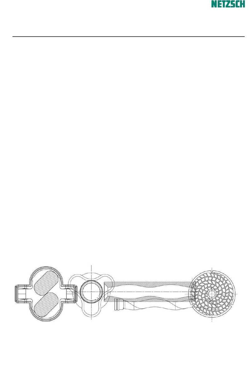
The NEMO®pump is a progressing cavity
pump.
The main components which determine the
systemdiscoveredbyProfessorRenéMoineau
arearotatingpart,calledtherotorandasta-
tic part, called the stator.
The rotor is a helical screw with an extreme-
ly large pitch, large thread depth and small
centre diameter with round cross-section for
1/2-geometry and elliptical cross-section for
2/3-geometry. The stator has a two start or
resp. 3 start thread and is double or resp. 1.5
the pitch length of the rotor. This provides
spaceforthemediumbetweentherotorand
stator. When the rotor turns round inside the
stator the medium moves continuously from
the inlet to the outlet.
The universal NEMO®pump system unifies
many positive characteristics of other pump
types:
■Like centrifugal pumps NEMO®pumps
have no suction or pressure valves, but do
have a stable flow rate in proportion to the
number of revolutions.
■Like piston pumps NEMO®pumps have a
suction capability of up to 8.5 m vacuum
metric.
■Like membrane and peristaltic pumps the
NEMO®pump can transport every type of
inhomogenous,gaseousandabrasivemedia,
as well as those that are not of a liquid con-
sistencyorcontainsolidsand/orfibrousmate-
rial.
■Like gear pumps and screw pumps the
NEMO®pumpiscapableofcopingwithhigh
medium viscosities.
■Like piston, membrane, gear or screw
pumpstheNEMO®pumpcanperformdosing
operations.
Length and cross-sections through the rotor
and stator with 1/2-geometry during a
rotation.
0°/360°
90°
180°
270°
Rotor-
Stellun
g
STATOR
ROTOR
GB
Rotor
position

2 DESCRIPTION AND GENERAL DATA
PAGE
2.0R
Revision: 4 Date Name Signed
Substitute for issue issued 04.11.98 Mangel
of 05.08.98 approved 05.11.98 Denk
text no. 30100 released 06.11.98 Hantschk
copy to: 95
2.2 General Data
Noise emissions:
The maximum permitted noise emission level at a work place is 70 dB (A).
The noise level was measured in accordance with DIN Standard 45635-24-01-KL2
to assure that the pump does not exceed 70 dB (A).
Noises generated by the drive and pipes are not included in the above
emission value.
A prerequisite for the noise emission level of ≤70 dB (A) is that the pump
is operated in a cavity free regime and is bolted to a concrete base.
GB
Length and cross-sections through the stator with rotor
with reduced stator wall thickness
1/2-geometry
2/3-geometry

Date Name Signed Revision: 4
issued 23.06.98 Mangel Substitute for issue
approved 24.06.98 Denk of 07.12.94
released 25.06.98 Denk text no. 30100
copy to: 95
N
E
M
O
P
U
M
P
E
N
Continued Page 3.0R
N
E
M
O
P
U
M
P
E
N
3 PACKAGING, TRANSPORTATION, STORAGE PAGE
3.0
3 Packaging, Transportation, Storage
3.1 Packaging and Transportation
NEMO®pumps are shipped in railroad containers or crates
unless the customer specifies otherwise.
The packings are labelled and symbols give the handling instructions
in accordance with DIN 55402.
On receipt check for any transport damages.
Transport damages should be reported to the transporter immediately.
The pumps should be transported as closely as possible to the location
of installation and only there should they be uncrated.
Uncrated horizontal pumps should be lifted by using a shackle which
can be attached to the baseplate. The bolt holes of the frame or
the lifting lugs attached to the baseplate could be used as shown on
the installation drawing.
Vertical pumps should be lifted by using the bolt down holes,
lifting lugs or shackles attached to the baseplate. This is shown on
the installation drawing. For most applications, the drive is mounted
on top of the pump.
Be careful when lifting top heavy pumps. The centre of gravity may be
above the points where the lifting gear is attached to. If the case, secure
additionally against tipping over!
Vertical pumps should not be deposited unless they are secured vertically.
Hazards of tipping! Deposit only in horizontal position!
It is essential to avoid that the total pump unit be suspended with
eye bolts of the motor or gear box. These eye bolts should be used
for lifting the motor and/or the gear box only.
The Accident Prevention Rules, Section 18.4 relating to lifting accessories
for the lifting of loads (VBG 9a) must be strictly adhered to.
Because of the variety of possible pump designs and applications, only
general instructions can be given here. These should be good enough
for experienced assemblymen or transportation experts.
When in doubt, please ask for detailed information on the pump unit
concerned.
GB

3 PACKAGING, TRANSPORTATION, STORAGE
Continued Page 3.1
PAGE
3.0R
Revision: 4 Date Name Signed
Substitute for issue issued 23.06.98 Mangel
of 07.12.94 approved 24.06.98 Denk
text no. 30100 released 25.06.98 Denk
copy to: 95
When moving the pump or unit on wheels strictly attend to the following:
■Pad lock the motor drive and secure against unintended starting up.
■Move the pump unit carefully and slowly, especially where the ground is
uneven. Hazards of tipping!
■Ensure a stable position of the pump or unit at the operating/storage place
and secure it by actuating all clamping devices on all the wheels or rollers
against voluntary moving away.
■Where fitted loosely, carefully watch the pipe bends when pumping.
Power of repulsion!
■Where necessary, secure the pump unit additionally with support blocks.
3.2 Storage
The pumps are preserved for transport unless specified otherwise.
In cases of longer storage the pumps should be handled as follows
until installation:
■Stator:
If the pump is not to be used immediately, then the elastomer along
the contact line between rotor and stator may become permanently
distorted (compression-set). This will increase the break away torque.
Therefore, the stator should be removed and kept separately in a clean,
cool and dry environment.
Standard DIN 7716 summarizes detailed information on the storage
of rubber products, some of which is gathered here, and the following
notice applies to a storage for a period of up to six months.
General
Most of the rubber products may change their physical properties
under unfavourable conditions or if treated improperly, which will
result in a shorter lifetime.
Or they may become useless through excessive hardening, aging,
regenerating or permanent deformation, also because of blistering,
cracking or other damages appearing on the surfaces.
The changes may occur under the influence of oxygen, ozone, heat,
light, humidity, solvents or because of storing the products under
tension.
If stored and treated properly, the rubber products will keep their
properties, even over a long period of time (some years), almost
unchanged.
This does, however, not apply to uncured rubber compounds.
GB
Table of contents
Other NETZSCH Water Pump manuals
Popular Water Pump manuals by other brands

Clarke
Clarke GSE1 Operation & maintenance instructions

FILL-RITE
FILL-RITE FR100 Series Installation and operation manual
FLOJET
FLOJET quad II diaphragm 4125 series user guide

CVS
CVS 50-14-DMV instruction manual

Glentronics
Glentronics The Basement Watchdog Special instruction manual
Wilo
Wilo TWI 5 Installation and operating instructions
Flotec
Flotec Vort 130/5 Auto Use and maintenance manual

Grundfos
Grundfos MAGNA3 25-100 (N) instructions
VERDER
VERDER VERDERFLEX Dura 55 Series operating manual
Euromatic
Euromatic SPC 250 operating instructions

Franklin Electric
Franklin Electric Inline 1100 Installation and operation manual

Liberty Pumps
Liberty Pumps LEH Series installation manual
