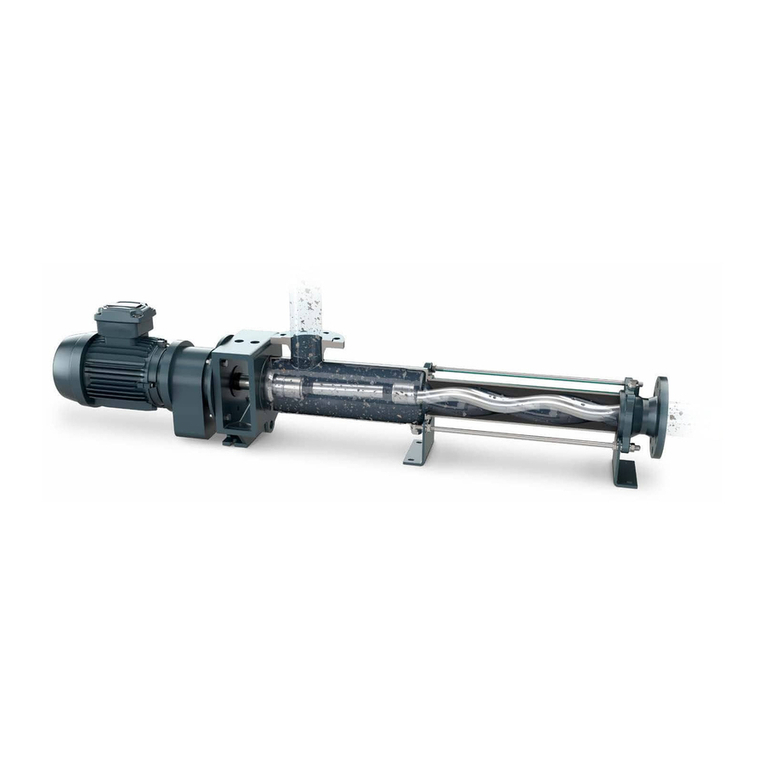
NETZSCH NM038BY Manual

Type:
Machine no.:
Commission:
Date of release:
Reference:
Operating and Maintenance Instructions
Original Instructions
NETZSCH Pumps & Systems - Solutions you can trust v
NM038BY
D8411276
4300003998/000100
21.02.2018
4500201470

The NETZSCH Group is an owner-managed technology company which operates
internationally and has its registered office in Germany.
The Business Units – Analyzing & Testing, Grinding & Dispersing and Pumps & Systems
– stand for tailored solutions of the highest quality. Over 2,500 employees at 130 sales
and production centres in 23 countries all over the world ensure that expert service is
always available close to our customers.
With
NEMO®progressing cavity pumps, TORNADO ®rotary lobe pumps, screw pumps,
grinding machines, dosing systems and accessories the Pumps & Systems Business Unit
offers customised and sophisticated solutions for the most diverse applications on a
global level.
NETZSCH Pumpen & Systeme GmbH
Geretsrieder Str. 1
84478 Waldkraiburg, Germany
Tel.: +49 - (0) 8638 - 63 0
Fax: +49 - (0) 8638 - 67 999
© NETZSCH Pumpen & Systeme GmbH - Subject to technical changes.

TABLE OF CONTENTS AGE
0.0
issued: 14.10.2015 Revision: 9 text no.
00001-1/1
copy to:
AGE
1 Safety recautions 1.0
2 Description 2.0
3 acking, Transportation, Storage 3.0
4 Installation Instructions 4.0
5 Start-up 5.0
6 Temporary Shutdown 6.0
7 Maintenance 7.0
8 Trouble-Shooting and Remedying 8.0
9 Dismantling and Assembly of the ump Housing 9.0
10 Dismantling and Assembly of the Rotating arts 10.0
11 Dismantling and Assembly of the Connecting Shaft 11.0
12 Dismantling and Assembly of the Shaft Sealing 12.0
13 Dismantling and Assembly of Special Units 13.0
14 Recommended Stock of Wear arts 14.0
15 Spare arts List, Sectional Drawings, Data Sheet 15.0
16 Contacts 16.0
17 Certificates / Annexes 17.0
IPP - EN - EN_00001_20151014/1 - D8411276 - 4300003998 - 000100 - NPS - 00229929 N 2018-02-21 19:03:25
3

Important Note
These Operating and Maintenance Instructions are to familiarise the user/operator
with the machine and the use of the machine.
This Instruction Manual:
• is only valid for this machine (see Machine Number and Order Confirmation
Number)
• contains important information on how to operate the machine safely, properly and
efficiently. Observing these instructions will help to avoid danger, to reduce repair
costs and downtimes and to increase the reliability and life of the machine
• must be read and applied by any person responsible for carrying out work with and
on the machine, such as:
- operation (including setting up, troubleshooting in the course of work, disposal of
production waste, fuels and consumables)
- maintenance (including service, inspection and repair)
- transport
• must always be available wherever the machine is in use
• shall be completed by the user or their authorized personnel to comply with
national requirements for the prevention of accidents and protection of the
environment
In addition to these operating instructions and the mandatory rules and regulations
for accident prevention and environmental protection in the country and place of use
of the machine, the generally recognized rules for safe and proper working of
machinery must also be observed.
The illustrations in these instructions may not always correspond exactly to the
present machine. But they describe correctly the basic structure and the sequence of
work steps.
!
IPP - EN - EN_00001_20151014/2 - D8411276 - 4300003998 - 000100 - NPS - 00229929 N 2018-02-21 19:03:25
4

1 SAFE Y PRECAU IONS AGE
1.0
issued: 03.05.2016 Revision: 3 text no.
01004-1/3
copy to:
Danger to general public
Risk of electric shock
Risk of injury from machinery
Danger from suspended loads
Damage to machinery
Risk of injury to eyes: goggles required.
1 Safety precautions
This manual contains basic instructions which must be observed when installing,
operating and servicing the machine / equipment. It is essential therefore for the user /
installer or responsible technician to read the manual thoroughly prior to installation
and operation.
A copy of the manual must always be at hand where the machine / equipment is
being used. In addition to the general safety instructions listed in this main section on
safety, it is necessary to observe the special safety rules included in other sections of
the manual, eg. for private use.
1.1 Safety signs
The signs below are printed in the manual as general hazard / danger symbols to mark
those safety instructions whose non-observance can result in danger to personnel or
to the machine / equipment. These signs are:
IPP - EN - EN_01004_20160503/1 - D8411276 - 4300003998 - 000100 - NPS - 00229929 N 2018-02-21 19:03:25
5

1 SAFE Y PRECAU IONS
AGE
1.0R
Warning plates located directly on the pump/equipment showing for example
- the correct direction of rotation
- the fluid connections
must always be observed and kept completely legible.
1.2 Qualified personnel
For safety reasons, all work on this machine may only be performed by qualified
personnel. Qualified personnel are persons who have sufficient knowledge in the
following areas as a result of their specialist training, experience and the instruction
they have received:
- Safety regulations
- Accident prevention regulations
- Technical guidelines and recognised technical rules
Qualified personnel must:
- be able to assess assigned work and to recognise and avoid potential dangers.
- be authorised by the manager responsible for system safety to perform the
required work and operations.
1.3 Dangers arising from non-observance of the safety instructions
Non-observance of the safety instructions may endanger persons and the environment
and may damage the machine.
Non-observance of the safety instructions may lead to loss of any claims for damages.
Specifically, non-observance may, for example, have the following consequences:
- Hazard to persons from electrical, mechanical and chemical influences.
- Hazard to the environment from leakages of hazardous materials.
- Loss of important functions of the machine.
- Failure of prescribed maintenance and repair methods.
1.4 Safety instructions for the user / operator
LIf there is a risk of danger from any hot or cold machine component, the user must
fit protective guards to prevent such components from being touched (according to
Standard EN 563).
Lrotective guards fitted to prevent contact with moving parts (eg. couplings) must
be in position when the machine is in use.
LLeakages (eg. from a shaft seals) of hazardous materials (eg. explosive, toxic, hot
material, etc.) must be discharged and disposed of in such a way that neither
personnel nor the environment are placed at risk. Legal directives must be
observed.
LAll possible danger from electricity must be eliminated (eg. refer to the regulations
in force of your local power supply company).
text no.
R 01004-1/3
issued: 03.05.2016 Revision: 3
copy to:
IPP - EN - EN_01004_20160503/2 - D8411276 - 4300003998 - 000100 - NPS - 00229929 N 2018-02-21 19:03:25
6

1 SAFE Y PRECAU IONS AGE
1.1
- The operator must carry out a risk assessment of the workstations at the machine in
his area of responsibility and issue operating instructions on the basis of the
assessment.
- The operator must name a person who is responsible for operating the machine
safely and coordinating all work at the machine.
- ersonnel must:
- observe all industrial safety regulations and operating instructions
- perform their tasks properly
- read and understand the operating instructions
- use personal protection gear
- ersonal protection gear consists of:
- Industrial safety clothing
- Safety shoes
- Safety gloves
- For overhead installation: Industrial hard hat
- The operator must provide this personal protection gear. The operating conditions
of the machine must be observed in this regard (e.g. operating temperature and
hazardous media) (→data sheet - Chapter 15). The operator must also issue
operating instructions on how to use the personal protection gear, provide regular
documented training for personnel and ensure that instructions are observed.
- The operator must attach mandatory signs to the machine or in the vicinity of the
machine in a clearly visible location and in a clearly legible condition.
- The operator must inform the personnel of the hazards associated with the conveyor
medium and the means of protection.
1.5 Safety instructions for maintenance, inspection and installation
- The operator must ensure that all maintenance, inspection and installation work is
performed by authorised and qualified personnel, who have understood the
operating instructions and are trained appropriately.
- Work on the machine may only be performed when the machine is at a standstill
and the power supply has been switched off and secured against being switched
on again (e.g. by removing the fuse or attaching a padlock to the main switch).
- The machine must be depressurised and emptied. The procedure described in the
operating instructions to bring the machine to a standstill must be observed in all
cases (→Chapter 6).
- Let the machine cool to below 50 °C/warm to above 0° C, or wear personal
protection gear (→Chapter 1.4).
issued: 03.05.2016 Revision: 3 text no.
01004-2/3
copy to:
IPP - EN - EN_01004_20160503/3 - D8411276 - 4300003998 - 000100 - NPS - 00229929 N 2018-02-21 19:03:25
7

1 SAFE Y PRECAU IONS
AGE
1.1R
- Media and lubricants that escape during maintenance must be wiped off
immediately and disposed of in accordance with environmental regulations. Wear
slip-resistant shoes!
- All safety and protection equipment must be reattached or reactivated and tested
immediately after maintenance work has been completed.
- The actions listed in the step "Start-up" (→Chapter 5) must be followed before
restarting.
- Because the required time intervals for cleaning and maintenance work depend
very heavily on the conveyor medium and the other operating conditions, it is not
possible in most cases to give fixed intervals.
he required intervals for cleaning and maintenance must be determined
and laid down by the operator in operation.
1.6 Unauthorised modifications, use of original parts
- Modification or changes to the machine are only permissible upon consultation and
with the written agreement of NETZSCH.
- For reasons of operating and equipment safety, the supplied machines may only be
operated with original spare parts and accessories and auxiliary materials
authorised by NETZSCH in accordance with NETZSCH specifications.
- Any warranty is void if other parts or materials are used!
1.7 Specified use, improper application
This machine is solely for the purposes of conveying the conveyor media, referred to
the data sheet (→Chapter 15) and under the operating conditions which are also
described there.
Any usage which goes above and beyond this must be agreed with NETZSCH in all
cases and shall only be permitted following written approval from NETZSCH.
The operational safety of the supplier machine is only guaranteed if it is used for its
specified purpose.
This machine has been designed on the basis of defined operating conditions. The
limit values for the operating conditions are specified on the data sheet (→Chapter 15)
and must be observed in all cases.
text no.
R 01004-2/3
issued: 03.05.2016 Revision: 3
copy to:
IPP - EN - EN_01004_20160503/4 - D8411276 - 4300003998 - 000100 - NPS - 00229929 N 2018-02-21 19:03:25
8

1 SAFE Y PRECAU IONS AGE
1.2
As a result of the application of current EU law in the field of system operator's
liability and the associated issues surrounding permission to operate a system, we
would like to draw your attention to a requirement for operation that is mandatory
for our products:
Spare parts and expendable parts from other manufacturers are not
authorised for use in our products and breach the operating instructions
delivered to you with the product.
Using spare parts from other manufacturers may have a negative impact on
operating safety and safety at work. Any use of our products with spare
parts from other manufacturers is not permitted.
In the event that products are used with spare parts from other
manufacturers, any consequences for the operating licence of your overall
facility and any consequences under liability law shall be your sole
responsibility.
1.8 Specific points for the use of a NEMO®pump
A NEMO®pump must be used for the purpose only for which it was sold.
If you change or wish to change the process medium, you must check with either the
supplier or manufacturer that the pump is suitable for the new medium. This is
especially important with aggressive, poisonous or otherwise hazardous substances.
ump criteria include:
1. Compatibility with the pumped media
2. Suitability for seal design / material, especially the shaft seal
3. Resistance to pressure and temperature of the media
The NEMO®pump is a positive displacement pump and as such is able to generate
pressures that exceed the pumps design limit.
A blockage or the chance closure of a valve in the discharge line can cause a pressure
rise manifold as high as can be tolerated by the installation. This can result in
the bursting of pipes, which must be avoided especially in the case of dangerous
media.
Corresponding safety equipment must therefore be installed, for example an
emergency stop button, a pressure relief valve with return pipe or a bursting disc.
During maintenance and repair work on the pump please note the following:
1. Ensure that the pump drive can not be turned on without authorization
2. When opening the pump follow the instructions for handling the medium (eg.
protective clothing, no smoking etc)
3. Before putting the pump back into operation ensure that all guards and other
safety devices (eg. drive–belt protection, coupling protection) are properly re–
installed
issued: 03.05.2016 Revision: 3 text no.
01004-3/3
copy to:
IPP - EN - EN_01004_20160503/5 - D8411276 - 4300003998 - 000100 - NPS - 00229929 N 2018-02-21 19:03:25
9

1 SAFE Y PRECAU IONS
AGE
1.2R
1.9 Notes on inspection and repair
The statutory regulations on safety at work, accident prevention regulations and
environmental protection regulations oblige all commercial undertakings to protect
their employees, persons and the environment from the negative effects of handling
hazardous materials.
Important:
Machines and their parts may only be inspected / repaired if the ”Safety clearance
certificate ( echnical Declaration)” has been filled in correctly and fully by
authorised and qualified personnel and is available.
he ”Safety clearance certificate ( echnical Declaration)” can be
downloaded from our website at: ”https://pumpen.netzsch.com/” or please
contact our service team
(→Chapter 16 - Contacts).
If special safety precautions are required when emptying and cleaning the machine,
the necessary information must be provided in the certificate.
The ”Safety clearance certificate (Technical Declaration)” is part of the
inspection/repair order and must always be filled in and signed when NETZSCH is to
carry out inspection/repair. However, the reserved right of NETZSCH to reject this
order remains unaffected.
text no.
R 01004-3/3
issued: 03.05.2016 Revision: 3
copy to:
Always consider and observe your safety during operation, maintenance
and installation of the machine. Please adhere to the EC-Directive for
Machinery including national regulations and follow the European
Standard EN 292 with the accident prevention rules laid down by the
trade unions and other appropriate technical institutions.
IPP - EN - EN_01004_20160503/6 - D8411276 - 4300003998 - 000100 - NPS - 00229929 N 2018-02-21 19:03:25
10

1 SAFETY PRECAUTI NS PAGE
1.3
issued: 03.05.2016 Revision: 3 text no.
01013-1/2
copy to:
1.10 Instructions concerning explosion protection
The instructions below are to be considered and kept to when using pumps
in potentially explosive areas in order to guarantee durable explosion
protection of the pumps and avoid any danger of ignition.
The pumps have the approval for applications in areas II 2G IIB T4 X (-20 ≤
Ta ≤ +60 °C), II 2G IIB T3 X (-20 ≤ Ta ≤ +60 °C), II 2GD IIB T4 X (130 °C) X (-20
≤ Ta ≤ +60 °C), II 2GD IIB T3 (195 °C) X (-20 ≤ Ta ≤ +60 °C) or I M2 c X (+5 ≤
Ta ≤ +40 °C) according to the directive 2014/34/EU (ATEX) [Ta = ambient
temperature].
It has to be taken into account that in case of aggregates the components
(e.g. gears, couplings) mounted on the pump must comply with the directive
2014/34/EU as well. The relevant documentation concerning these
components has to be considered.
The application area of aggregates is determined by the application area of
the mounted component with the lowest approval and thus may deviate
from the allowed application area of the pump.
The declaration of conformity, as defined by the ATEX directive 2014/34/EU,
will become invalid if spare parts other than the ones manufactured or approved y
NETZSCH are used.
The manufacturer's warranty, as granted in the ordering documents, will also ecome
invalid, ecause the safety of operator and/or machine can no longer e guaranteed.
The maximum conveying product temperatures apply when mechanical seals of
Messrs. Burgmann with carbide - carbide and carbide - carbon as sliding material
com inations are used.
In the case of other manufacturers or other sliding material com inations it is
necessary to consult the manufacturer.
Temperature category max. surface temperature for
dust
max. temperature of the con-
veying product
T4 130 °C 100 °C
T3 195 °C 165 °C
T2 295 °C 265 °C
T1 445 °C 415 °C
IPP - EN - EN_01013_20160503/1 - D8411276 - 4300003998 - 000100 - NPS - 00229929 N 2018-02-21 19:03:25
11

1 SAFETY PRECAUTI NS
PAGE
1.3R
1. Assembly and repair in potentially explosive areas
When performing assem ly and repair work, it has to e seen to that no danger of
ignition arises especially during heating up the pump parts. This means e.g. heating up
y explosion-proof heating devices or exclusively in non-explosive areas. The
temperature of the heated part and the ignition temperature of the materials which
cause the danger of explosion have to e considered.
2. Dry-running protection
Under no circumstances is the pump to run dry. The pump is to e equipped with an
appropriate dry-running protection device.
The device for dry-running protection should e self-regulating.
This means that this device can give alarm signals and/or switch off the pump also in
case of failures in its own control system.
3. verpressure protection
The pump must not e loaded over the maximum allowa le pressure. The pump is to
e equipped with an appropriate overpressure protection device. The pump must not
convey against a closed slide valve.
The overpressure protection device should e self-regulating.
4. Drives
The drives must e adjusted to the performance of each pump. In the case of a
locking of the pump, the drives must e turned off automatically y means of a
motor protection unit.
5. Potential equalization
All conductive parts of the pump are to e integrated in the potential equalization of
the pumping set unless the conductive connection to the ground potential is
guaranteed y the drive or connecting shafts or otherwise.
6. Stator
The stator is to e regularly checked for wear.
When the allowa le wear limit is reached, the stator is to e replaced. Before
exchanging the conveying product, the pump operator has to consult the
manufacturer concerning the dura ility of the stator unless the stator has already
een confirmed for the intended application.
Inspection and maintenance interval of the stator:
- in the case of an operating time of > 16 h/day, at least twice a year
- in the case of an operating time of < 16 h/day, at least once a year.
text no.
R 01013-1/2
issued: 03.05.2016 Revision: 3
copy to:
IPP - EN - EN_01013_20160503/2 - D8411276 - 4300003998 - 000100 - NPS - 00229929 N 2018-02-21 19:03:25
12

1 SAFETY PRECAUTI NS PAGE
1.4
7. Joints / joint lubrication
The sealing and the lu rication of the joints are to e regularly checked. If necessary,
the seals and the lu ricants are to e replaced.
Inspection and maintenance interval of the joints:
- in the case of an operating time of > 16 h/day, at least twice a year
- in the case of an operating time of < 16 h/day, at least once a year.
8. Inspection after initial startup
The aspects relevant for ensuring the explosion protection (such as lu rication and
wear check) are to e checked six months after the initial startup of the pump at the
latest.
9. Materials
Although eing allowed as material for the pumps, aluminum should e avoided in
potentially explosive areas.
The pumps may only e used if, under the particular operating conditions, the
materials are resistant to mechanical and/or chemical influences or corrosion such that
the explosion protection will e maintained.
10. Gland
If a gland packing is applied it has to e o served that the permitted temperature
corresponding to the temperature category is not exceeded. Recommendation: fasten
the screws of the stuffing ox gland only with low torque (approx. 5 Nm).
11. Dust layer
No dust layer of more than 5 mm is allowed on the pumps. Rotating parts (like drive
shaft, earing carrier and drive stool of paddle agitators) must not run in a dust layer.
In respect of this the pumps have to e controlled at regular intervals and if necessary
the dust has to e removed.
issued: 03.05.2016 Revision: 3 text no.
01013-2/2
copy to:
IPP - EN - EN_01013_20160503/3 - D8411276 - 4300003998 - 000100 - NPS - 00229929 N 2018-02-21 19:03:25
13

This page is intentionally left lank.
IPP - EN - EN_01013_20160503/4 - D8411276 - 4300003998 - 000100 - NPS - 00229929 N 2018-02-21 19:03:25
14

2 DESCRIPTION AND GENERAL DATA PAGE
2.0
issued: 09.01.2013 Revision: 4 text no.
02000-1/1
copy to:
2.1 Desc iption
he NEMO®pump is a progressing cavity
pump.
he main components which determine the
system discovered by Professor René Moineau
are a rotating part, called the rotor (R) and a
static part, called the stator (S).
he rotor is a helical screw with an extremely
large pitch, large thread depth and small centre
diameter with round cross-section for ½-
geometry and elliptical cross-section for
⅔-geometry. he stator has a two start or resp.
3 start thread and is double or resp. 1.5 the
pitch length of the rotor. his provides space
for the medium between the rotor and stator.
When the rotor turns round inside the stator
the medium moves continuously from the inlet
to the outlet.
he universal NEMO®pump system unifies
many positive characteristics of other pump
types:
LLike centrifugal pumps NEMO®pumps have
no suction or pressure valves, but do have a
stable flow rate in proportion to the number
of revolutions.
LLike piston pumps NEMO®pumps have a
suction capability of up to 8.5 m vacuum
metric.
LLike membrane and peristaltic pumps the
NEMO®pump can transport every type of
inhomogenous, gaseous and abrasive
media, as well as those that are not of a
liquid consistency or contain solids and/or
fibrous material.
LLike gear pumps and screw pumps the
NEMO®pump is capable of coping with high
medium viscosities.
LLike piston, membrane, gear or screw
pumps the NEMO®pump can perform
dosing operations.
0°/360°
90°
180°
270°
S
R
Length and cross-sections through the rotor
and stator with ½-geometry during a
rotation.
Rotorposition
2 Desc iption and Gene al Data
IPP - EN - EN_02000_20130109/1 - D8411276 - 4300003998 - 000100 - NPS - 00229929 N 2018-02-21 19:03:25
15

2 DESCRIPTION AND GENERAL DATA
PAGE
2.0R
text no.
R 02000-1/1
issued: 09.01.2013 Revision: 4
copy to:
2.2 Gene al Data
Noise emissions:
he maximum permitted noise emission level at a work place is ≤ 70 dB (A).
he noise level was measured in accordance with DIN Standard 45635-24-01-KL2.
Noises generated by the drive and pipes are not included in the above emission value.
A prerequisite for the noise emission level of ≤ 70 dB (A) is that the pump is operated
in a cavity free regime and is bolted to a concrete base.
Length and cross-sections through the stator with rotor with reduced stator wall
thickness
½-geometry
⅔-geometry
IPP - EN - EN_02000_20130109/2 - D8411276 - 4300003998 - 000100 - NPS - 00229929 N 2018-02-21 19:03:25
16

3 PACKAGING, TRANSPORTATION,
STORAGE
PAGE
3.0
3 Packa in , Transportation, Stora e
3.1 Packa in and Transportation
NEM ®pumps are shipped in railroad containers or crates unless the customer
specifies otherwise.
The packings are labelled and symbols give the handling instructions in accordance
with DIN 55402.
n receipt check for any transport damages.
Transport damages should be reported to the transporter immediately.
The pumps should be transported as closely as possible to the location of installation
and only there should they be uncrated.
Uncrated horizontal pumps should be lifted by using a shackle which can be attached
to the baseplate. The bolt holes of the frame or the lifting lugs attached to the
baseplate could be used as shown on the installation drawing.
Vertical pumps should be lifted by using the bolt down holes, lifting lugs or shackles
attached to the baseplate. This is shown on the installation drawing. For most
applications, the drive is mounted on top of the pump.
Be careful when lifting top heavy pumps. The centre of gravity may be above the
points where the lifting gear is attached to. If the case, secure additionally against
tipping over!
Vertical pumps should not be deposited unless they are secured vertically. Hazards of
tippin !
Deposit only in horizontal position.
It is essential to avoid that the total pump unit be suspended with eye bolts of the
motor or gear box. These eye bolts should be used for lifting the motor and/or the
gear box only.
The local accident prevention rules relatin to liftin accessories for the
liftin of loads must be strictly adhered to.
Because of the variety of possible pump designs and applications, only general
instructions can be given here. These should be good enough for experienced
assemblymen or transportation experts.
When in doubt, please ask for detailed information on the pump unit concerned.
When moving the pump or unit on wheels strictly attend to the following:
IPad lock the motor drive and secure against unintended starting up.
IMove the pump unit carefully and slowly, especially where the ground is uneven.
Hazards of tippin !
issued: 27.07.2013 Revision: 7 text no.
03000-1/2
copy to:
IPP - EN - EN_03000_20150727/1 - D8411276 - 4300003998 - 000100 - NPS - 00229929 N 2018-02-21 19:03:25
17

3 PACKAGING, TRANSPORTATION,
STORAGE
PAGE
3.0R
IEnsure a stable position of the pump or unit at the operating /storage place and
secure it by actuating all clamping devices on all the wheels or rollers against
voluntary moving away.
IWhere fitted loosely, carefully watch the pipe bends when pumping. Power of
repulsion!
IWhere necessary, secure the pump unit additionally with support blocks.
3.2 Stora e
The pumps are only preserved for transport and short term storage unless specified
otherwise.
In cases of long term storage the pumps should be handled as follows until
installation:
LStator:
If the pump is not to be used immediately, then the elastomer along the contact line
between rotor and stator may become permanently distorted (compression-set). This
will increase the break away torque.
Therefore, the stator should be removed and kept separately.
Standard DIN 7716 summarizes detailed information on the storage of rubber
products, extracts from which are stated here.
The following applies for a storage period of up to six months.
General:
Most rubber products may change their physical properties under unfavourable
conditions or if treated improperly, which will result in a shorter lifetime. They can
become unsuitable for use through excessive hardening, ageing, degeneration or
permanent deformation, or because of blistering, cracking or other damage appearing
on the surfaces.
These changes may occur under the influence of oxygen, ozone, heat, light, humidity,
solvents or because of storing the products under load.
If stored and treated properly, rubber products will retain their properties even during
long term storage (some years), with little change. However this does not apply to
uncured rubber compounds.
text no.
R 03000-1/2
5issued: 27.07.2013 Revision: 7
copy to:
IPP - EN - EN_03000_20150727/2 - D8411276 - 4300003998 - 000100 - NPS - 00229929 N 2018-02-21 19:03:25
18

3 PACKAGING, TRANSPORTATION,
STORAGE
PAGE
3.1
Store room:
- The environment in which rubber products are being kept must be cool, dry, free of
dust and naturally ventilated.
- Rubber products must not be stored in the open, not even in an area sheltered
from the weather.
- Rubber products should be stored at temperatures above minus 10 °C and not
more than plus 15 °C. Store rooms should not be damp and there should be no
condensation.
- Rubber products should be stored in an environment offering a relative humidity
under 65 %.
- Rubber products must be protected against light, particularly direct sunlight or high
UV artificial.
- Rubber products should be kept away from forced ventilation and draughts; under
these conditions they should be wrapped.
- As ozone is very aggressive and harmful to rubber products they should not be
stored in the same room with equipment likely to produce ozone, e.g. electric
motors or other equipment which could electrically discharge or cause sparks.
- Rubber products should not be stored together with solvents, oil, grease, lubricants
or any chemicals.
LRotor:
Please support with wooden blocks and cover up against harm from mechanical
impact.
For rotors of RCC (material number 1.2436):
coat the surfaces with protective grease to avoid rusting.
LShaft Sealin by packin land:
Remove the gland and coat the exposed shaft surface with grease.
LPump parts in stainless steel:
No grease coating necessary.
LOther, non-coated pump parts:
Protect with grease.
LDrives:
Please observe the drive supplier's instructions.
issued: 27.07.2013 Revision: 7 text no.
03000-2/2
copy to:
IPP - EN - EN_03000_20150727/3 - D8411276 - 4300003998 - 000100 - NPS - 00229929 N 2018-02-21 19:03:25
19

This page is intentionally left blank.
IPP - EN - EN_03000_20150727/4 - D8411276 - 4300003998 - 000100 - NPS - 00229929 N 2018-02-21 19:03:25
20
Table of contents
Other NETZSCH Water Pump manuals
Popular Water Pump manuals by other brands

Fruitland
Fruitland RCF 250 Operation and maintenance

Pentair
Pentair Hydromatic SP40 Series Installation and operation manual

Franklin Electric
Franklin Electric RL Series quick start guide

REED
REED B20HP manual

Flotec
Flotec 3601A SERIES owner's manual

Pontec
Pontec PondoClear Island 3000 operating instructions

KSB
KSB Vitastage Series Installation & operating manual

WOERNER
WOERNER GMZ-E Translation of the original operation manual

Hoval
Hoval Genius (06-35) operating instructions

Ingersoll-Rand
Ingersoll-Rand ARO PP10A Series Operator's manual

EBARA
EBARA WINNER Operating and maintenance manual

Armstrong
Armstrong 4280 Series Installation and operating instructions