neutral labs SCRAT v1.1 User manual

SCRAT v1.1
by neutral labs
Manual
Hello, owner.
SCRAT is an aggressive sounding multimode Steiner-Parker filter with a
twist: You can change the resonance response by plugging in components
like diodes, capacitors or resistors directly to the front panel. A
set of preset cartridges is also available, which gives you instant
access to a variety of filter sounds.

Specifications
●Width: 9 HP
●Supply voltage: +12V/-12V (Eurorack 10-pin header)
●Current draw:
○+12V: 35 mA
○-12V: 35 mA
○5V: unused, 0 mA
●CV inputs: 2x 0V to 10V usable, -12V to 12V absolute
Connecting SCRAT to Eurorack power
Connect a 10 pin Eurorack power cable to the 2x5 power header on the
back of the module. There is an arrow indicator next to the word
STRIPE on the circuit board. Unsurprisingly, the red stripe side of
the cable goes on the side that says STRIPE. The module (and your
power supply) is protected in case you should ever connect it the
wrong way around, but it won’t turn on if you do.
Module Function
SCRAT is a 2-pole (-12 dB/Octave) multimode Steiner-Parker filter
(VCF) that offers high-pass and low-pass modes and is quite aggressive
sounding.
In addition to the built-in sound-shaping possibilities, the user can
optionally modify the filter’s character by plugging passive
electronic components like diodes, capacitors or resistors into either
or both of two modifier ports on the front panel, or special pre-made
cartridges that contain small circuits made up of such components.
SCRAT also includes a pre-filter drive circuit that can be used to
further shape the sound.

Manual Controls
Control
Function
This switches the filter mode from high-pass (top position)
to low-pass (bottom position).
This changes the type of resonance. In the top position,
you will get a clean resonance curve while in the bottom
position there will be added harmonics that heavily distort
the sound – a dirty type of resonance.
Note: The specific result may be different in case
components or cartridges are currently inserted into the
modifier ports (see below).
In case the resonance type switch is in the bottom position
(dirty resonance), this switches between primarily high
additional harmonics (top position) as indicated by the
treble clef and predominantly low additional harmonics
(bottom position) as indicated by the bass clef.
Note: The specific result may be different in case
components or cartridges are currently inserted into the
modifier ports (see below).
RESO
This changes the filter’s resonance (Q factor). In the
fully counterclockwise position, there is no resonance.
Around the 10 o’clock position, the filter will start to
self-resonate (depending on the other controls’ settings),
with the intensity increasing up to the fully clockwise
position.
FREQ
This determines the cutoff frequency for the filter. In the
fully counterclockwise position, the frequency is at its
minimum (high-pass filter fully open, low-pass filter fully
closed) and vice versa.
PRE
This changes the pre-filter drive intensity. In the fully
counterclockwise position, there is no additional drive.
While rotating the knob towards the fully clockwise
position, the amplitude of the signal is gradually
increased, with an emphasis on high frequencies. Due to the
Steiner-Parker filter's excellent response to being driven
in this way, it is recommended to make use of this
functionality as often as possible. :)

FREQ CV
AMOUNT
(unlabeled –
bottom right
knob)
If no cable is inserted into the cutoff frequency CV jack,
this acts as a secondary cutoff frequency control, which is
added to the current FREQ setting. The range of this knob
is limited, making it a control for fine adjustments. The
full range can only be accessed by adjusting both knobs,
however, with this knob set to the 12 o’clock position, the
FREQ knob by itself should cover most use cases.
If a cable is inserted into the cutoff frequency CV jack,
this attenuates the CV signal. In the fully
counterclockwise position, no CV modulation occurs. With
some skill and possibly the use of a tuner app, it is
possible to get 1V/Octave tracking for the cutoff
frequency.
Note: The cutoff frequency depends on the RESO setting, so
changing the resonance will also slightly adjust the
cutoff. This is inherent to the Steiner-Parker filter
design. If you need 1V/Octave tracking throughout your
track or performance, do not change the RESO setting once a
satisfactory tracking has been established.
Control Voltage (CV) Inputs
Both CV inputs expect signals within the 0V to +10V range. Don’t worry
about supplying a higher or lower CV though: It will not harm the
module. CV modulation at frequencies within the audio range is both
possible and recommended.
Input
Function
RESO
This controls the intensity of the filter resonance, similar
to the RESO knob. If a cable is inserted, both the incoming
CV and the knob will manipulate the resonance amount.
FREQ
This adjusts the filter cutoff frequency. The intensity of
CV modulation is determined by the unlabelled FREQ CV AMOUNT
knob (bottom right knob). The front panel graphics indicate
the multiplication taking place between the CV and the FREQ
CV AMOUNT value. The LED behind the X indicates the
resulting FREQ setting.

Modifier Ports
The ports on the top of the module labeled P|S|G|S|P support the
plugging in of pre-assembled cartridges available from Neutral Labs,
as well as individual passive components like resistors, capacitors or
diodes. LEDs and LDRs (light-dependent resistors) can be used as well,
even in combination. Any combination of components and/or cartridges
will change the resonance behavior in its own unique way.
There are 2 rows of ports which work exactly the same, and they can be
used at the same time. E.g. it is possible to connect two cartridges
to both rows of ports simultaneously, or one cartridge and a number of
components on the other row of ports. When using cartridges, their
orientation doesn’t matter, they will work the same way facing either
up or down.
Caution: As shown by the warning icon to the top left of the ports, do
not use normal (unipolar) electrolytic capacitors unless you know
exactly what you’re doing! Reverse voltage may make them explode
violently. You may use them with the positive leg on one of the P
ports and the negative leg on one of the G ports, but it is better to
avoid them completely. Large value bipolar ceramic capacitors are
easily available and should be used instead. The use of active
components like transistors could result in unexpected behavior and
might damage the module, so avoid them as well. An exception would be
a BJT with either its emitter or its collector leg remaining
unconnected. Rule of thumb for the novice user: Plugging in any kind
and combination of diodes, resistors and ceramic capacitors is always
safe.
Connection type
Function
Parallel (P)
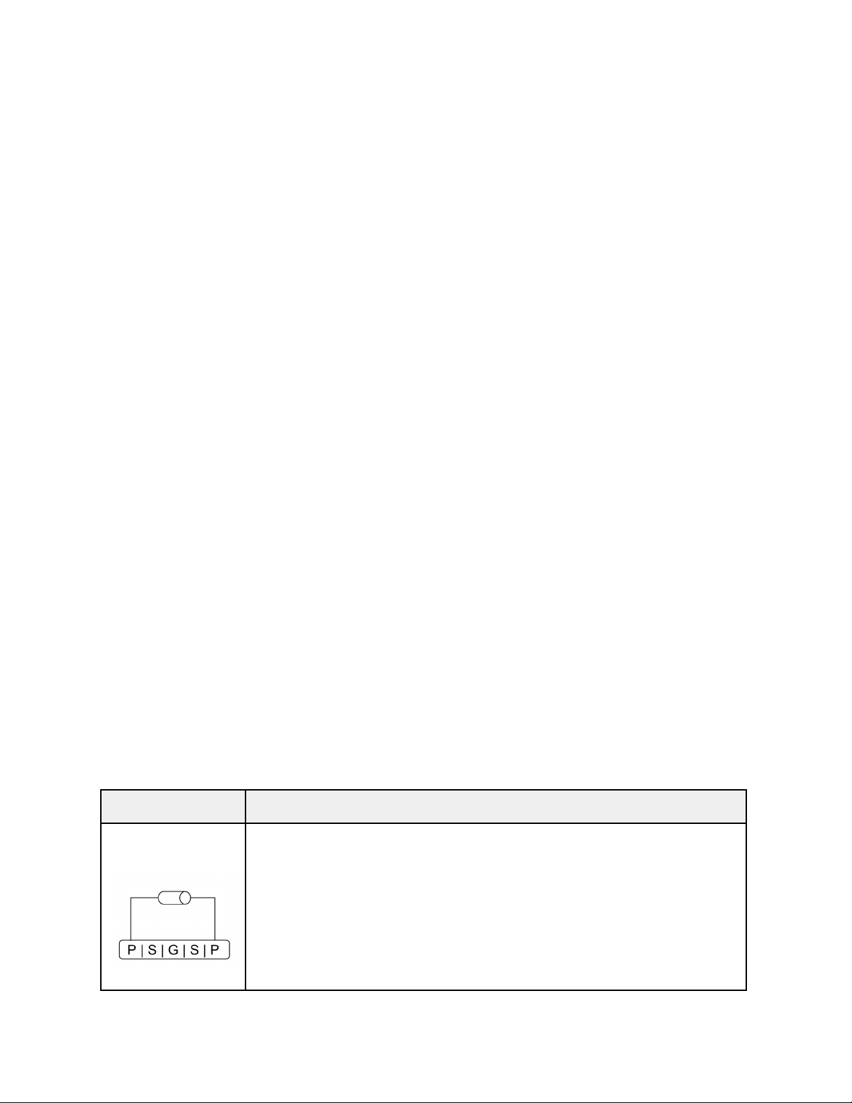
Connecting a component between the left and right P ports
puts this component in parallel to the filter’s main
feedback circuit. Doing the same on the other row of
ports will put both of these components in parallel.
Accidentally shorting these ports will not harm your
component or the module, as the circuit is protected by
100 Ohm resistors on either side.

Serial (S)
This is used for putting two components in series, the
combination of which will then be in parallel to the
feedback circuit.
Put the first of the two components from P to S and the
other one from the other S to the other P. Both of the S
ports on either row are interconnected (as visualized by
the half circles on the front panel graphics), so a
series connection will be made between the components.
You could e.g. put a resistor between P and S on the left
side, and an LED between S and P on the right side.
Ground (G)
This is for components that should go from the feedback
circuit to ground. In this case, components should be
placed in such a way that one of their legs connects to
any P port and the other connects to a G port.
In case two components should go to ground in series,
connect the first one between a P and an S port and the
second one between the other S port on the same row and a
G port. In case two components should go to ground in
parallel, connect either of them to one of the P ports
and both of their other legs to a G port.
Accidentally shorting from P or S to ground will not harm
your component or the module, as the circuit is protected
by a 1k resistor to ground.
Modifier Port Patch Ideas
●Diodes or LEDs work well in parallel, especially if using two different
diode types while their polarities are opposite each other, so e.g. a
Schottky diode on port row 1 and an LED in reverse on port row 2.
●Light-dependent resistors (LDRs) can be used. Put an LDR in parallel
and change the amount of light it receives (either by shining a light
on it or using your hand to cover it in a well-lit room). You can also
put an LDR in series with a diode in order to adjust the amount of
effect the diode has.
●You may use an LED in conjunction with an LDR, in various combinations.
Place the LED close to the top of the LDR, so the light from the LED
modifies the LDR’s resistance.
●Capacitors to ground give sonically interesting results, as they will
bleed high frequencies from the feedback loop, resulting in harmonics
created in the resulting audio signal.
Table of contents
Other neutral labs Music Pedal manuals