New World GSM-x31-3bi User manual

1
Universal GSM Intercom/Opener
(forVIDEX, FARFISA intercoms)
Model: GSM-x31-3bi
New World Security
36 Esker Meadow Green
Lucan
Co.Dublin
IRELAND
Ph:+353863310929
tech.support
gsmalarms@eircom.net
www.new-world-security.com

2
INTRODUCTION
The information in this manual is intended as an installation and commissioning guide
for the GSM door intercom system. This manual should be read carefully before the
installation commences.
Any damage caused to the equipment due to faulty installations where the information
in this manual has not been followed is not the responsibility of New World Security.
SYSTEM INTRODUCTION
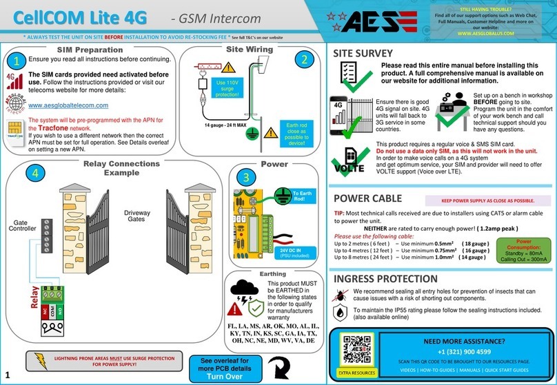
The GSM Gate Intercom-Opener model: GSM-x31-3bi perfect for secured residential
and commercial property, with worldwide remote control from your mobile handset.
GSM x31-3bi can be installed outside the premises on the gate as an intercom.
When the Intercom call button is pressed, the GSM Intercom will dial out to the pre-
programmed ADMIN number and inform the owner about the visitor at the gate.
The ADMIN can answer the call and speak to the visitor and open the gate with one of
the buttons of his phone if he wishes to let the guest in.
Next way to open gate for Pre-programmed Users, just need dial to the gate number,
this is Free of charge!
SYSTEM FEATURES
* GSM Quad-band GSM/GPRS module for use in Europe and U.S
* 6 INPUTS and 4 RELAY OUTPUTS (optional 16 INPUTS)
* 4 Gate Independent Remote control by SMS (each gate separate)
* Access control by free call for Authorised Users
* Gate open/close by timer (hold open or time delay switch)
* Each User gate access management
* Up to 250 users optional 500 users
* Automatic call credit control with SMS alert
* Remote system parameters control
* Easy installation and automatic setup
* Add or Delete Users by SMS
* Service Engineer system remote programming and testing
* LED lights for system status control
* 12 volt mains power
* PCB dimensions 110 x65 mm, Weight 0.1kg

3
INSTALLATION
FARFISA INTERCOM

4
VIDEX INTERCOM

5
CONNECTION
DESCRIPTION
1 12V 12VDC 1A
2 GND Ground connection
INTERCOM
3 -MIC Microphone -
4 +MIC Microphone +
5 SPK Speaker
6 SPK Speaker
7 KEY Auxiliary input connect to intercom call
button
8 KEY Auxiliary input connect to intercom call
button
INPUTS
10 COM Input signal Ground connection
11 1 Input signal No1
12 2 Input signal No2
13 3 Input signal No3
14 4 Input signal No4
15 5 Input signal No5
16 6 Input signal No6
17 COM Input signal Ground connection
RELAY OUTPUTS
18,19
R1 OptoMOSFET Relay Output 60VDC 0.1A
20,21
R2 OptoMOSFET Relay Output 60VDC 0.1A
22,23
R3 OptoMOSFET Relay Output 60VDC 0.1A
24,25
R4 OptoMOSFET Relay Output 60VDC 0.1A
Note: An antenna must always be connected. Always route the GSM cable away from
the microphone wires and the power supply wires to avoid interference on the speech
module.
IMPORTANT NOTE ABOUT SIM CARD
When using a pay monthly SIM card you must ask the service provider to put a spend limit
on the account (Vodafone call this service ‘spend checker’). This is to safeguard against
possible problems which could result in a large phone bill at the end of the month. All
providers offer this service. You will need to either ring them or e-mail them to set this up.
Automatic top ups should also have a monthly limit.

6
IMPORTANT!
When mounting the GSM antenna, choose a location which is away from human interaction
and away from the alarm panel. Route the GSM antenna cable from the GSM BackUp so
that it is separate from the power supply cables Always ensure the power is off to the GSM
BackUp before inserting or removing the SIM card.
New SIM cards will need registering before they can be used. Full details of how this is
done can normally be found in the SIM card pack. It will normally require that the SIM card
is inserted into a mobile phone, a number dialled and instructions followed. While the SIM is
in the mobile phone it would be a good time to disable any PIN codes, call diverts, ring back
and disable features such as voicemail and text alerts. Details of how to do this can be found
on the SIM card provider’s web site or by calling their customer services. Please use one of
the following SIM card providers (Vodafone, TMobile, O2 or Orange). We do not
recommend using 3 at this present time.
SYSTEM SETUP
To make easy Installation, we made smart option on this GSM BackUp system and all main
programming job, system will do automatically!
1. Insert SIM card with disconnected PIN code to GSM System
2. Connect Alarm panel DIALLER, and Telephone Line to GSM BackUp connectors.
3. Switch power ON.
4. When READY LED ON, switch off power, remove SIM card from GSM system and insert
in to your mobile phone ,then go to Address Book to edit ADMIN and USER numbers.
All others settings (SMSCONFIG and WORKCONFIG) system will enter automatically
by Factory default.
5. If you want to change GSM system settings, you can do direct on SIM card from your
handset, or remotely by SMS.

7
After automatic system programming, please take out THE SIM card from THE
GSM device and insert in to mobile phone. On the SIM card address book you will see
information which you can edit:
ADMIN 1
+4400000000 Administrator (ADMIN) has the permit:
(ADD/DELETE User numbers check the call credit balance, control Output Relay by SMS)
SERVICE
+353863310929 have permit only for remote programming: (NO GATE CONTROL)
(SMSCONFIG, SMSINPUTCONFIG, TIMECONFIG WORKCONFIG, get INFO, SMS)
SMSCONFIG Text message configuration (see 2. On User manual)
000000
SMSINPUTCONFIG Inputs configuration to send text messages when Inputs are
triggered (see
3. On User manual)
0000000000000000
TIMECONFIG Intercom dialling, talk time configuration (see 5.
On user manual)
15251010
USER1 1
+4400000000 User1, first from 3 main users who can control gate if Admin not
answer on Intercom mode. Also can control Outputs Relay by text message-if selected,
permit SMS control)
USER2 1
+4400000000
USER3 1
+4400000000
WORKCONFIG
000000 Working configuration options (see 1. On user manual)
*100#
01 Call credit balance code combination (see 5. On user
manual)

8
1. SYSTEM WORK CONFIGURATION
Name cell: WORKCONFIG
Number field cell: 110000
Comment:
1st number = permission to control relays, if any relay is switched On.
"0" = deny. "1" = allow;
2nd number = control relays via SMS.
"0" = all users. "1" = only administrator;
3rd number =Dial to ADMIN if any Inputs triggered.
"0" = deny. "1" = allow;
4th number =Inputs/Outputs Extension module up to 16 Inputs.
"0" = not connected. "1" = connected;
5th number = controller operating mode.
"0" = Gate Intercom/Opener mode. "1" Alarm system mode;
6th number = Alarm Siren activation (in Alarm mode only).
"0" = only when Alarm. "1" = short beep, Arm/Disarm mode (not use in Intercom mode)
2. SYSTEM SMS CONFIGURATION
Name cell: SMSCONFIG
Number field cell: 010010
Comment:
1st number = SMS about power On/Off.
"0" = deny. "1" = allow;
2nd number = sending SMS to Administrator (ADMIN) when calling
unauthorized person to system
"0" = deny. "1" = allow;
3rd number = SMS about Relay On/Off activation.
"0" = deny. "1" = allow anyway; "2" = allow if Relay On; "3" = allow if Relay Off;
4th number = send SMS about external inputs status
"0" = send to admin. "1" = send to the admin and Users;
5th number = call credits limit balance information SMS
"0" = send to administrator and Service engineer. "1" = send to any number by request;
6th number = response SMS to manage security reaction (not use in Intercom mode)
"0" = only who arm/disarm the alarm. "1" = who arm/disarm alarm and send copy SMS to
the Admin number also;

9
3. SMS INPUT CONFIGURATION
Name cell: SMSINPUTCONFIG
Number field cell: 0000000000000000
Comment:
1st number = SMS about Input No1
2nd number = SMS about Input No2
3rd number = SMS about Input No3
4th number = SMS about Input No4
5th number = SMS about Input No5
6th number = SMS about Input No6
7th number = SMS about Input No7
8tht number = SMS about Input No8
9th number = SMS about Input No9
10th number = SMS about Input No10
11th number = SMS about Input No11
12th number = SMS about Input No12
13th number = SMS about Input No13
14th number = SMS about Input No14
15th number = SMS about Input No15
16th number = SMS about Input No16
When Input is triggered, controller will send SMS to Admin number
"0" = deny. "1" = send SMS on connection and disconnection, "2" = send SMS on connection
NO, "3" = send SMS disconnect NC , Alarm mode settings- “4”=Full control Inputs
(doors, windows, motion sensors), “5”= external perimeter control beams
4. ENGINEER SERVICE NUMBER
Name cell: SERVICE
Number field cell:+353863310929
Comment:
Telephone number Service engineer :( can only do remote system programming)
* By default is Manufacturer number +353863310929 but you can change it to your service
engineer number
5. CONFIGURATION TIME INTERVALS
Name cell: TIMECONFIG
Number field cell: 15251001
Comment:
1st and 2nd number = Intercom dial time to Admin number in sec. (01-99sec)
3rd and 4th number = talk time with a door intercom when the call has been answered in sec.
(01-99sec)
5th number = Output relay off delay in sec (1-9) on short call relay control mode
6th number = Cal credit balance checking in hours. (0-9h) (0-do not check)
7th and 8th number = Siren working time in alarm mode (01-99sec), Unused in Gate
Intercom/Opener mode.

10
6. CHECKING THE BALANCE
Call credit balance control and minimum balance settings by SDL code:
Name cell: *xxx #
Number field cell: 05
Comment:
Different Operator has different call credits control code combination.
In the number field is from 1 to 4 numbers (0-9999), meaning the balance on the account.
The tools below a certain threshold, the Administrator will copy phone SMS from operator
with balance.
*Note: The balance can only be checked if the correct balance check string has previously
been stored using SDL code
7. ADMIN AND 3 MAIN USER NUMBERS
Name cell: ADMIN 1
Number field cell:+4400000000000
Comment:
Administrator phone number: (only for control and add/dell numbers)
No programming option
Name cell:USER1 1
Number field cell:+4400000000
Comment:
USER1 number and can control only Relay1
Name cell:USER2 123
Number field cell:+4400000000000
Comment:
USER2 number and can control only Relay1, Relay2 and Relay3
Name cell:USER3 14
Number field cell:+440000000000
Comment:
USER3 number and can control only Relay1 and Relay4
.
*Note: All entered symbols are CAPITAL

11
8. SYSTEM OPERATION
CONTROL Output Relay by SMS
Format SMS to control relay : <Rxxx ><xHxxMIN>
Examples:
Relay 1 in 5 minutes: R1ON 5 MIN
Relay 2 to 8 hours 26 minutes: R2ON 8H26MIN
Relay 3- turn On R3ON
Relay 3- turn Off: R3OFF
Format answering SMS: <RXxx >
Example: R1On
Example: R2Off
Control relay via SMS (similar like a short free call to the controller):
Format SMS to manage: <OPEN>
Example: OPEN
Getting information about the device:
Format SMS query: <INFO>
Example: INFO
Response SMS: Voltage13 .8V; Network 72%; Temper. + 24 c. R1-ON; R2-OFF; R3-OFF;
R4-ON
Getting information from the operator's account and other information:
Format SMS query: <CREDITS> < > request format
Example: CREDITS *101 #
Example: CREDITS *101*#
Response SMS: device sends a copy of the text received from the Network operator.
Add new user (maximum 500 subscribers including administrator):
SMS-format to add: <ADD> < username > new
Example: ADD + 380509631994
Format response SMS:
Example: Number+ 380509631994 Add.
Remove the selected user:
Format SMS to remove: <DEL> > < number
Example: DEL + 380509631994
Format response SMS:
Example: Number+ 380509631994 Deleted.

12
SERVICE Query content configuration of cells:
Format SMS query: < name > <?>
Example: WORKCONFIG ?
Example: SMSCONFIG ?
Example: SMSINPUTCONFIG ?
Example: TIMECONFIG ?
Format SMS: < name > < <:> cell data >
Example: WORKCONFIG:0001
Example: SMSCONFIG:00101
Example: SMSINPUTCONFIG:0000110101000000
Example: TIMECONFIG:152512
Controller INPUT name settings:
If alarm Input is NC and disconnected loop, controller send alarm SMS with text which you
can change by your request:
Format SMS to setup text: <TXT> > < Input number><:><new text max20
Example:
SMS text for Input1 connect TXT I1ON: Alarm temperature!
SMS text for Input1 disconnect TXT I1OFF: Normal temperature
SMS text for Input8 connect TXT I8ON: Alarm! Door OPEN!
SMS text for Input1 disconnect TXT I8OFF:Alarm message 1 OFF
SERVICE Replace the contents of the configuration:
(to replace just edit it and send SMS , came in response to a query)
Format SMS to replace: < name > < <:> cell data >
Example: WORKCONFIG :1001
Example: SMSCONFIG :11101
Example: SMSINPUTCONFIG :0101110000000000
Example: TIMECONFIG :152584
Format response SMS: Write config SIM is successful!
SMS about the call to the module is not listed in a Subscriber SIM card:
If User not from controller address book will call in to the system, controller take dialler
number and resend to Admin number.
Format SMS: The attempt is not authorized access:+ 353509631994

13
ALARM system control by SMS
Alarm activation ARM
Format SMS query: ARM
Format response SMS:
If sensors not ready : ARM not possible! Please check Input sensors
When all OK : OK! System ARMED!
If system was ARMED: Warning! System already ARMED
Perimeter Alarm activation ARM PERIMETER
Format SMS query: ARM PERIMETER
Format response SMS:
If sensors not ready : ARM not possible! Please check Input sensors
When all OK : OK! Perimeter ARMED!
If system was ARMED: Warning! System already ARMED
Alarm deactivation DISARM
Format SMS query: DISARM
Format response SMS:
When all OK : OK! DISARMED!
If system was DISARMED: Warning! System already DISARMED
OUTPUT RELAY control by phone
(Gate Intercom/Remote mode)
When GSM controller receives a call from USER, it will check the calling number and if
the number is in the list you have prepared it will reject the call and switch On Relay.
The GSM system doesn't answer the call; it simply checks the caller ID.
Your network must send the caller ID otherwise it will not work.
Usually operators don't charge until you answer the call, so it won't cost you anything to
control external equipment.
(Alarm mode)
When WORKCONFIG 5th number is “1” (Alarm system mode) , OUTPUT Relay :
R1 –alarm LED Indicator
R2- siren
R3,R4- for any other external equipment control by SMS
To ARM Alarm system – need make a call to controller and after 2-3 rings hang-up handset
System call-back once, to confirm- system Armed (not need answer to call).
To DISARM – need make a call to controller and wait until controller reject call. System
Disarmed. If in one minute will be no trigger signal on any Input, system will go to ARM
mode automatically, and call-back once, to confirm- system is Armed (not need answer to
call).

14
Manufacturer: www.New –World-Security.com
2011
Table of contents
