Newco Vista Vend Original operating instructions

Installation, Operation, Replacement Parts and Service Manual

2
Table of Contents
Product Compartment Loading........................................................................................................3
Installation........................................................................................................................................4
Operation..........................................................................................................................................5
Removal of Major Components.......................................................................................................6
Disassembly of Major Components.................................................................................................8
-Front Cover...........................................................................................................................8
-Product Trays........................................................................................................................9
-Control Heart ........................................................................................................................9
-Back Cover ...........................................................................................................................11
-Locking Cover......................................................................................................................11
-Carousel................................................................................................................................12
-Base.......................................................................................................................................12
Exploded Views ...............................................................................................................................13
-Control Box ..........................................................................................................................13
-Coin Box...............................................................................................................................15
-Back Shell.............................................................................................................................17
-Lock Cover ...........................................................................................................................19
-Door ......................................................................................................................................21
-Tray.......................................................................................................................................23
-Carousel................................................................................................................................25
-Base.......................................................................................................................................27
Specifications ...................................................................................................................................28

3
Product Compartment Loading
1. Product compartment segments are designed in 1/3 pie segments for easy removal from the Vendor. These
compartments telescope up after they are installed in the Vendor *See Figure 1. Once removed from the
Vendor the compartments collapse to the same level to allow for ease of loading *See Figure 2. The
product compartments are designed with individual bin dividers to allow larger products fit into the
product compartments, price is the same per product regardless if a bin divider (“A”) is used or not B *See
Figure 3. This allows flexibility when stocking the machine.
2. Product Compartments and coinbox are designed to fit into the cargo box, *See Figure 4.
Fig 4
Fig 1
Fig 2 Fig 3
Level 1
Level 2
Level 3
Level 4
A

4
Installation
1. Place Vista Vend on a sturdy, level, flat,
surface.
2. Plug the AC to DC Adaptor into a 120-volt
AC receptacle.
3. Plug the AC to DC Adaptor power cord into
the Vista Vend’s receptacle located on the
back of the lower left side. *See Figure 1
Operation : Cash Box Removal
1. Unlock the front cover by inserting the key
into the lock and rotating it 1/4th turn
clockwise.
2. Remove the front cover by pressing in on the
lower right corner of the cover (“A”). Rotate
until cover has proper clearance for removal.
Lift the front cover from the vendor and set it
aside. *See Figure 2 *Note that the front
cover can be stored by setting it on the back
cover during route servicing.
3. Rotate the carousel by grasping the blue
rotation ring of the carousel and rotating it
until one of the three 120-degree segments of
trays is centered in the service opening.
4. Grasp the horizontal slot (“C”) in the center
of the top tray and lift the segment out of the
vendor. Set the segment of trays on a flat
surface and telescope all four trays down to
one level. *See Figure 3
5. Remove the coin box by rotating the coin box
counter-clockwise and aligning the “Remove-
Install” arrow on the coin box with the
reference arrow below. Pull the coin box out
horizontally and set it aside. *See Figure 4
Fig 1
Fig 2
Fig 3
Fig 4
Power
Outlet
Key Lock
A
Rotating Ring
C

5
6. Reinstall the coin box by aligning the “Remove-Install” arrow with the reference arrow on the bottom
of the coin box support. Rotate the coinbox clockwise until the “operate arrow” is lined up with the
reference arrow below.
7. Reinstall the 120-degree tray segment by grasping the horizontal slot in the center of the smallest tray
and lifting it to telescope the segment of trays up. Reinsert the tray segment into the vendor. Make
sure each of the four trays in the 120-degree segment are at the same height as the trays on the right
side and on the left side. If the trays are not the same height, the tray is not properly seated, and the
vendor will not operate.
8. Reinstall the front cover by placing it over the service opening and rotating the cover to the left until it
stops.
9. Turn the key counter clockwise ¼ turn to lock.
Operation : Product Purchase
1. To purchase a product from the Vista Vend,
rotate the carousel clockwise or counter-
clockwise by grasping the carousel rotating ring
and select a product to purchase. The product
you wish to purchase should be in the “Vend
Zone” *See Figure 5
2. Align the right side of the compartment
containing the desired product with the right
side of the door opening. *See Figure 6
3. Refer to the price posted on the tray level
containing the desired product.
4. Deposit coins in the coin box until enough credit
has been accumulated on the coin box display to
purchase the desired product.
5. Push the colored, numbered (1,2,3,4) button on
the coin box that corresponds to the color of the
door handle located above the product to be
purchased. *See Figure 7
Fig 6
Fig 7
Fig 5

6
6. Grasp the door handle of the same color as the button that was pushed and move the door to the left until
the door stops.
7. Reach in and retrieve the product.
8. After removing the product, close the door by moving the door all the way back to the right.
Removal of Major Components
1. Unlock the front cover by inserting the key into
the lock and rotating it 1/4th turn clockwise.
2. Remove the front cover by pressing in on
the lower right corner of the cover has proper
clearance for removal. Lift the front cover from
the vendor and set it aside. *See Figure 7
*Note that the front cover can be stored by
setting it on the back cover during route
servicing.
3. Rotate the carousel by grasping the rotation ring
of the carousel and rotating it until one of the
three 120-degree segments of trays is centered
in the service opening.
4. Grasp the horizontal slot in the center of the top
tray and lift the segment out of the vendor. Set
the segment of trays on a flat surface and
telescope all four trays down to one level.
*See Figure 8
5. Remove the coin box by rotating the coin box
counter-clockwise and aligning the “Remove-
Install” arrow on the coin box with the
reference arrow below. Pull the coin box out
horizontally and set it aside. *See Figure 9
Fig 7
Fig 8
Fig 9

7
6. Remove the 3 screws on the left side of the
service opening that secures the locking cover
assembly. *See Figure 10
7. Remove the locking cover assembly by lifting it
vertically. *See Figure 11
8. Grasp the back-up slide arm (gray color) and
push up until the lock member arm (gray color)
can be separated from the back-up connect
blocks (gray color). *See Figure 12
9. Remove the 4 screws on the left side and the 5
screws on the right side of the control heart
assembly. *See Figure 13
10. Push in at the bottom of the right side of the
control heart assembly and snap the control
assembly off the back cover.
11. To remove the back cover, remove the screw
located below the coin box support at the top of
the steel tube. Remove the 2 screws at the
bottom left side of the back cover and rotate the
back cover counter-clockwise until the tabs
along the bottom perimeter of the cover are
clear of the tabs on the base. *See Figure 14
12. Grasp the back cover on the top with the right
hand and spread the lower left side of the cover
out with the left hand. Lift the back cover from
the base.
13. To remove the carousel, retract each detent
wheel (dark purple color) slightly and lift the
carousel enough above the detent wheel, so the
detent wheel can move under the carousel and
release the spring tension.
14. After both detent wheels are released under the
carousel, lift the carousel off the base. Remove
the thrust washer located on the steel tube under
the carousel.
Fig 10
Fig 11
Fig 12
Fig 13
Fig 14

8
15. Remove the detent wheels from the base by
sliding the wheels out from the center until they
clear the retaining tabs of the base. Lift out the
detent wheel, the spring applicator (dark purple
color), and the spring.
16. To remove the lock member arm (gray color)
and the lock member latch (gray color), remove
spring and then lift them vertically from the
base. * See Figure 15
17. Remove the lock member rocker (gray color)
by rotating the lock member rocker to the left
until it snaps out of the retaining bosses on the
base. Remove the rocker spring from the base.
Disassembly of Major Components
FRONT COVER:
1. Remove the door brackets B or C from each door by removing the screw on the back of the door bracket.
2. Remove the door handles by removing the screw on the underside of the handle.
3. Remove the doors by sliding them to the left and out of the front cover.
4. Remove the door vanes from the door by removing the mounting screws.
5. Remove all 4 lever covers from the front cover
by removing the screws underneath the lever
covers.
6. Remove all 8 door levers. Note: Lever “L” is
used on all 4 levels on the left side of the front
cover, and “R-1” is used on levels 1, 2, & 3 on
the right side of the cover. “R-2” is used on
level 4 on the right side of the front cover.
7. Remove the 3 front cover latches located on the
left side of the front cover by removing the
mounting screws form the back of the latches.
8. To reassemble the front cover, perform the
above steps in reverse order.
Fig 15

9
PRODUCT TRAYS:
1. To disassemble a product tray segment, telescope all trays down to one level, grasp the largest tray, and lift
it off the other trays. Repeat this process for the remaining trays.
2. To assemble the product trays, grasp the smallest tray and slide the second smallest tray down over the “T”
tabs of the smaller tray. Repeat this process for the remaining trays.
CONTROL HEART:
1. Turn the control heart assembly upside-down with the upper and lower cams (green color) facing up.
2. Remove the nut and lock washer from both cams. Remove the mounting screws from the two metal cross
braces and set cross braces aside.
3. Remove the upper and lower cam and also remove both metal cam bushings.
*Note: The upper cam has the shorter step and the lower cam has the longer step.
4. Turn the control heart assembly face up and remove the back-up actuator (gray color) by unsnapping it
from the mounting bosses.
5. Slide the back-up slide arm (gray color) up until the notch at the bottom of the slide arm lines up with the
horizontal round boss above. Continued on the next page.

10
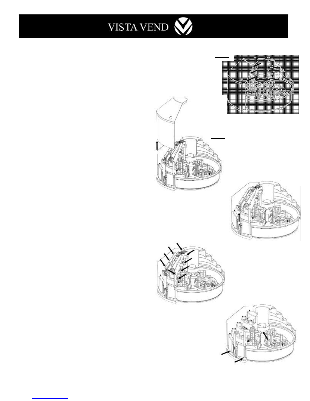
6. Lift the back-up slide arm from the control heart assembly. Note: The round boss is used to hold the
back-up spring during testing and service only. Remove and attach the back-up spring below on the side of
the lock member arm (gray color) for vending operations.
7. Move the lower cam slide arm (green color) back until the notches at the bottom of the lower slide arm line
up with the retaining tabs above. Lift the lower cam slide arm up to clear the retaining tabs, and then pull
the lower cam slide arm back horizontally to remove.
8. Pull the upper cam slide arm back and lift it out of the control heart assembly.
9. To remove the lock slide arm, turn the control heart assembly upside-down. Remove the screw and
metal arm from the bottom of the lock. Turn the assembly back upright, and lift the slide arm off the
vertical side of the control heart assembly. Slide the lock slide arm back horizontally and remove. To
reinstall the lock slide arm, perform the above steps in reverse.
10. To remove the lock, remove the retaining nut and the lock from the control heart assembly. To reinstall the
lock, perform the above steps in the reverse order.
11. Remove the back up connect blocks from the control heart assembly by pulling them up and snapping them
from their mounting bosses.
12. Remove the lock (orange color) of the back-up actuator (gray color) by pulling the lock to the side enough
to free the pin from the hole and turn the lock ¼ turn and slide the lock off the spring. The spring can be
removed from the back up actuator by twisting and pulling on the spring at the same time.
13. Remove the lock (orange color) of the back-up actuator (gray color) by pulling the lock to the side enough
to free the pin from the hole and turn the lock ¼ turn and slide the lock off the spring. The spring can be
removed from the back up actuator by twisting and pulling on the spring at the same time.
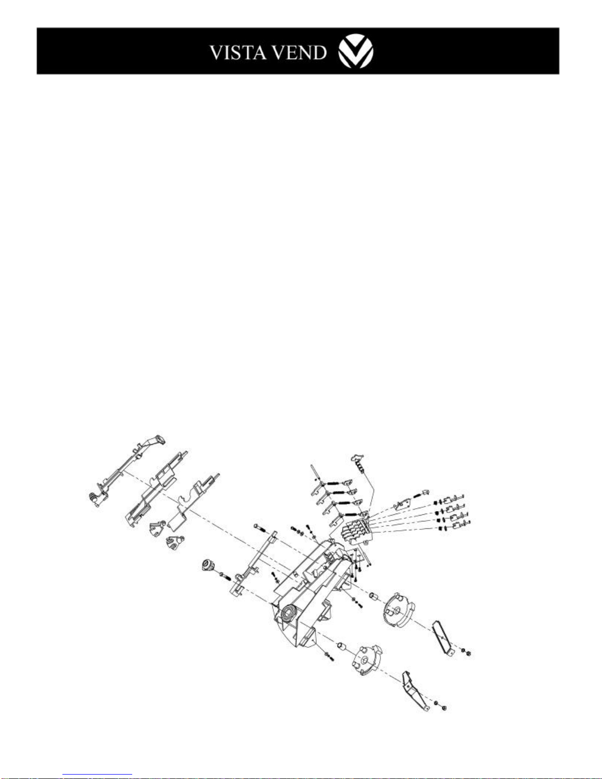
1. Remove the back-up actuator assembly (gray color).
2. Remove the four lever springs and remove the screw to the right of the 4 door latches (orange color).
Lift the steel latch shaft on the free end and pull horizontally to remove. Then remove the 4 latches (orange
color).
3. Remove the back-up push arm for key (orange color) by prying up gently on each end until it pops out.
4. Remove the shaft for the “V” actuators (orange color) by prying up on the right end of the shaft. Pop it up
and remove it horizontally.
5. Remove the 4 press springs and the 4 press plates (orange color).
6. Remove the 4 “V” actuators by pulling up on the push key (orange color) and sliding the “V” actuators off
to the side. Remove the four push keys.
7. To re-assemble the door latch system, perform the above steps in reverse.

11
LOCKING COVER:
1. Remove bracket “L” and bracket “R” by removing the mounting screws.
2. Remove the 3 “U” nuts from the locking cover upper section by spreading the nuts enough to clear their
mounting hole and pulling them off.
3. To remove the locking cover upper section from the locking cover lower section, remove the 5 mounting
screws and pull the covers off.
BACK COVER:
1. Remove mounting plate “C” with attached circuit board and unplug the power cord.
2. Remove the coin box support by rotating it clockwise.
3. Remove connecting plate “A” from the back cover by removing the 8 mounting screws.
4. Remove the connection plate “B” by removing the mounting screw.
Locking Cover
Back Cover

12
CAROUSEL:
1. To remove the two center pieces from the 6 tray supports, free one slot at a time in the center piece by
squeezing the 2 prongs of the tray support together and pulling the center piece away from the prongs
while holding pressure on the center piece to keep other depressed prongs from re-latching. Do this on
all 6 slots of the center piece, and it will pull free from the tray supports.
2. To remove the 6 tray supports from the carousel, squeeze the 2 prongs together (through the slots in the
carousel), and pull the tray supports out of the carousel slots.
BASE:
1. To remove the carousel rollers, lift the rollers from their retaining bosses on the base.
2. The roller shaft can be removed from the rollers by removing one of the “E” clips.
3. Remove the steel tube from the base by removing the screw at the base of the tube.
4. Remove the feet from the base by removing the two screws and the wing nut on top of the base. Remove
the foot cup and the foot base from underneath the base.
5. The electrical wire that supplies power to the coin box can be removed by pulling the wire down out of the
steel tube and out from underneath the tabs on the base. Also, remove the nut on the jack on the lower left
side of the base. Pull the wire and the jack out of the base.
Carousel
Base

13
101 121020
LOWER CAM POM GREEN PMS347C 1
102 121021
UPPER CAM POM GREEN PMS347C 1
103 121022
LOWER CAM SLIDE ARM POM GREEN PMS347C 1
104 121023
UPPER CAM SLIDE ARM POM GREEN PMS347C 1
105 121024
BACKUP SLIDE ARM POM GREY PMS424C 1
106 121049
CONTROL HEART SUPPORT-APC BLACK 1
107 121050
CONTROL HEART SUPPORT-BPC BLACK 1
108 121107
BACKUP SPRING OD8x42, DIA0.8 Ni-PLATED 1
109 121025
BACKUP CONNECT BLOCK POM GREY PMS424C 2
110 121026
LATCH -A POM ORANGE PMS021C 2
111 121108
CAM LOCK J-35834-CAM-TBD-14 1
112 121109
KEY 2
113 121027
LOCK SLIDE ARM POM GREY PMS424C 1
114 121110
LATCH SHAFT POLE STEEL DIA3.2x48.5 Ni-PLATED 1
115 121111
SCREW FOR LATCH STAINLESS STEEL M4x15PA 1
116 121112
LEVER SPRING OD4.0x28, DIA0.5 N-PLATED 4
117 121028
"V"ACTUATOR FOR LATCH POM ORANGE PMS021C 4
118 121001
NO 4.PUSH KEY POM ORANGE PMS021C 1
119 121002
NO 3.PUSH KEY POM ORANGE PMS021C 1
120 121003
NO 2.PUSH KEY POM ORANGE PMS021C 1
121 121004
NO 1.PUSH KEY POM ORANGE PMS021C 1
122 121113
SHAFT FOR"V"ACTUATOR DIA3.2x43.5 Ni-PLATED 1
123 121114
PRESS SPRING OD6.6x14.4, DIA0.4 Ni-PLATED 4
124 121005
PRESS PLATE POM ORANGE PMS021C 4
126 121012
BACKUP PUSH ARM FOR KEY POM ORANGE PMS021C 1
127 121115
SPRING OF BACK UP ACTUATOR OD4.4x16.1, DIA0.7 Ni-PLATED 1
128 121029
BACKUP ACTUATOR POM GREY PMS424C 1
129 121013
LOCK OF BACKUP ACTUATOR POM ORANGE PMS021C 1
130 121116
SCREW STAINLESS STEEL M3x8BT 4
131 121117
STEEL BUSHING DIA12.1xDIA12.9x16.7 Ni-PLATED 2
132 121118
HEXAGON SCREW M5x32 Ni-PLATED 2
134 121119
SPRING WASHER M5x9.0x1.3 Ni-PLATED 2
135 121120
E RING ETW-2.3 ACP 2
136 121121
HEXAGON NUT M5x(8)x4mm Ni-PLATED 2
137 121079
LATCH -B POM ORANGE PMS021C 1
138 121095
LATCH -C POM ORANGE PMS021C 1
140 121105
FIX BRACKET-ASTEEL T=1.2mm Zn-PLATED 1
141 121106
FIX BRACKET-BSTEEL T=1.2mm Zn-PLATED 1
142 121122
SCREW SYAINLESS STEEL M3x10PM 4
143 121123
FLAT WASHER ID3.3xOD10xT0.9 Ni-PLATED 4
144 121124
SPRING WASHER M3xOD5x0.7 Ni-PLATED 4
145 121125
FLAT WASHER ID4.2xOD9xT0.6 Ni-PLATED 1
146 121126
SPRING WASHER ID4.1xOD7.6x1.0 Ni-PLATED 1
147 121127
SILICON FLUID SF1000 1g

14

15
201 121073
COIN BOX-UPPER ABS BLACK 1
202 121074
COIN BOX-LOWER ABS BLACK 1
203 121075
COIN TRAY-APC RED PMS199C 1
204 121076
COIN TRAY-BPC RED PMS199C 1
205 121077
MOUNTING PLATE-AABS BLACK 1
206 121078
MOUNTING PLATE-BABS BLACK 1
208 121082
LOCK POLE PA66 BLACK 1
209 121083
LENS PC CLEAR RED PMS#194C 1
210 121080
PRESS PLATE -LEVERABS PINK PMS182C 1
211 121086
LOCK POLE KEY POM BLACK 1
212 121084
PUSH HANDLE PC COOL GREY PMS#11U 1
213 121087
PUSH LEVER POM L. PURPLE PMS263C 4
214 121085
LOCK WASHER PC COOL GREY PMS#11U 1
215 121088
PUSH KEY #1 POM BLUE PMS300C 1
216 121089
PUSH KEY #2 POM BLUE PMS300C 1
217 121090
PUSH KEY #3 POM BLUE PMS300C 1
218 121091
PUSH KEY #4 POM BLUE PMS300C 1
219 121081
PCB BRACKET ABS PINK PMS182C 1
220 121098
INFRARED TRANSMITTER PMMA CLEAR 1
221 121128
PIN-PUSH KEY SPP1.5x6 BLACK OXIDE 5
222 121129
SCREW STAINLESS STEEL M2.3x6PT 5
223 121130
SCREW STAINLESS M2.6x10PT 5
224 121131
SCREW STAINLESS STEEL M3x8PT 1
225 121132
SCREW STAINLESS STEEL M3x10PA 4
226 121133
SPRING A -COIN BOX OD7.4x26.1 DIA0.6 Ni-PLATED 1
227 121134
SPRING B -COIN BOX OD4.3x17.1, DIA0.3 Ni-PLATED 1
228 121135
ELECTRICAL CONTROL ASSEMBLY
1
229 121136
TRANSFORMER PRI: 120V 60Hz, SEC: 0.5A DC12V 1
230 121137
SCREW STAINLESS STEEL M3x10KA 3
231 121138
SCREW STAINLESS STEEL M3x6PT 2
232 121139
SCREW STAINLESS STEEL M2x5PM 9
233 121140
SCREW STAINLESS STEEL M2x5KM 1
234 121101
LOCK LATCH POM BLACK 1
235 121102
LATCH COVER POM BLACK 1
236 121141
SPRING-LOCK LATCH OD6.1x14, DIA0.3 Ni-PLATED 2
237 121142
SCREW STAINLESS STEEL M2.6x12KA 2

16

17
219 121081
PCB BRACKET ABS PINK PMS182C 1
222 121129
SCREW STAINLESS STEEL M2.3x6PT 5
301 121063
BACK SHELL PCTA DS2010 CLEAR 1
302 121072
COINBOX SUPPORT PC BLACK 1
303 121051
CONNECTING PLATE-APC BLACK 1
304 121030
CONNECTING PLATE-BPC BLACK 1
305 121068
HOUSING-LEVEL PC CLEAR 1
306 121069
BASE-LEVEL ABS WHITE 1
307 121070
COVER-LEVEL ABS WHITE 1
308 121143
SCREW STAINLESS STEEL M3x12PA 5
309 121144
BABY OIL 4mL 4mL
310 121099
PRESS BRACKET-APOM BLACK 3
311 121100
PRESS BRACKET-BPOM BLACK 2
312 121145
SCREW STAINLESS STEEL M3x10KA 1
313 121146
SCREW STAINLESS STEEL M4x15PA 1
314 121147
SCREW STAINLESS STEEL M5x16PA 2
315 121148
FLAT WASHER ID3.3xOD10xT0.9 Ni-PLATED 6
316 121149
SPRING WASHER M3xOD5x0.7 Ni-PLATED 25
317 121150
FLAT WASHER ID3.3xOD8xT1.0 Ni-PLATED 19
318 121151
SCREW STAINLESS STEEL M3x14PT 21
319 121152
FLAT WASHER ID4.2xOD9xT0.6 Ni-PLATED 1
320 121153
SPRING WASHER M4.1xOD7.6x1.0 Ni-PLATED 1

18

19
401 121071
LOCKING COVER UPPER PC BLACK 1
402 121060
LOCKING COVER LOWER PC BLACK 1
403 121031
BRACKET --LPC BLACK 1
404 121032
BRACKET --RPC BLACK 1
405 121154
U--TYPE NUT STEEL 13x22,T=0.7 Ni-PLATED 3
406 121155
SCREW STAINLESS STEEL M5x16PA 3
407 121156
SCREW STAINLESS STEEL M3x10PA 11

20
Table of contents
Popular Merchandiser manuals by other brands

Hussmann
Hussmann IMPACT CW2-GE datasheet

Global Refrigeration
Global Refrigeration ULG30BS Installation and operation instructions

EPTA
EPTA iarp AB 400 PV FARMACIA Use and maintenance

FBD
FBD 56X Series Installation & operation manual

Howard McCray
Howard McCray R-CMS34E-10 Specifications

Framec
Framec EXPO J500 PT datasheet