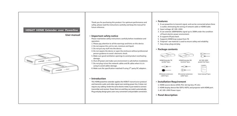
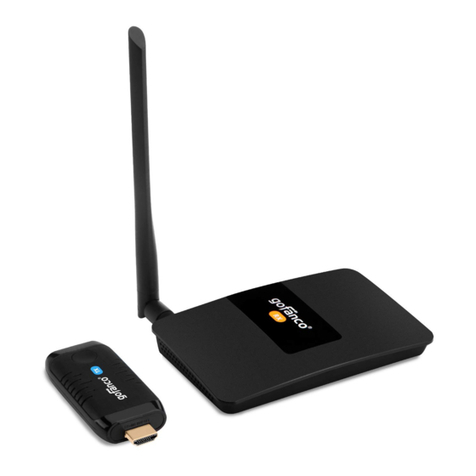
NEWlink NL-HPW200 User manual

PLC Wireless Extender
User Manual
V1.0

NL-HPW200 User Manual
i
Contents
About User Manual...................................................................................................1
Organization.............................................................................................................1
1Overview.........................................................................................................4
2Hardware Description......................................................................................6
2.1 LED Status..........................................................................................6
2.2 Interface Description ...........................................................................7
2.2.1 The Ethernet Interface..............................................................7
2.2.2 The Adapter's Buttons...............................................................8
2.3 Hardware Installation...........................................................................9
2.3.1 System Requirements...............................................................9
2.3.2 Before You Begin......................................................................9
2.4 Operation Range.................................................................................9
2.5 How to Improve the Transmission Capacity.......................................10
2.6 Wireless Roaming.............................................................................10
3Wireless Network Configuration..................................................................... 11
3.1 TCP/IP Settings................................................................................. 11
3.2 Log In to the Web Page.....................................................................14
4Web Configuration.........................................................................................15
4.1 Internet Settings................................................................................15
4.1.1 LAN........................................................................................15
4.1.2 DHCP Clients..........................................................................18
4.2 Wireless Settings ..............................................................................18
4.2.1 Basic ......................................................................................19
4.2.2 Advanced ...............................................................................30
4.2.3 Security ..................................................................................37
4.2.4 WPS.......................................................................................46
4.2.5 Station List..............................................................................50
4.3 Administration ...................................................................................50
4.3.1 Management...........................................................................51
4.3.2 Upload Firmware ....................................................................53
4.3.3 Settings Management.............................................................53

NL-HPW200 User Manual
ii
4.3.4 Status .....................................................................................54
4.3.5 Statistic...................................................................................55
4.3.6 System Command..................................................................56
4.3.7 System Log.............................................................................57
5Install the PowerLine Utility............................................................................59
6How to Use The Utility Software ....................................................................61
6.1 Main Tab...........................................................................................61
6.2 Privacy Tab.......................................................................................63
6.3 Diagnostics Tab ................................................................................64
6.4 About Tab .........................................................................................66
7How to use the NMK Pushbutton...................................................................67
7.1 Forming a HomePlug AV logical network...........................................67
7.2 Joining a Network..............................................................................68
7.3 Leaving a Network.............................................................................68
8About PowerLine QoS...................................................................................70
9Parameter and Specification..........................................................................71

NL-HPW200 User Manual
1
About User Manual
This user manual mainly describes how to install and configure the NL-HPW200
wireless extender.
Organization
This user manual is organized as follows:
Chapter
Description
Chapter 1 : Overview
Provides a general overview of the NL-HPW200
wireless router, and the package list.
Chapter 2 : Hardware
Description
Mainly describes the front panel and the rear
panel of the NL-HPW200 and the procedure for
hardware installation.
Chapter 3 : Wireless
Network Configuration
Describes how to configure network settings of
your PC, then connect to the NL-HPW200.
Chapter 4 : Web
Configuration
Mainly describes how to navigate through the
Web pages and how to configure the
parameters.
Chapter 5 : Install the
PowerLine Utility
Introduce installation of the PowerLine Utility
Chapter 6 : How to use the
Utility Software
Describes how to view the PowerLine
parameter, modify NMK, device name
Chapter7 : How to use the
NMK pushbutton
Introduce how to form, join and leave a
HomePlug AV local network
Chapter8 : About PowerLine
QoS
Introduce how to setup the QoS parameter in
PowerLine function
Chapter9 : Parameter and
Specification
Introduce the product system specification

NL-HPW200 User Manual
2
Features
PowerLine Feature
Power supply range of 100 ~ 240VAC 50/60Hz
Comply with HomePlug AV, and Co-existence with HomePlug 1.0 Nodes
PowerLine phy rate up to 200 Mbps
Support QAM 1024/256/64/16/8, QPSK, BPSK, and ROBO modulation
schemes
128-bit AES Link Encryption with key management for secure power line
communications
Windowed OFDM with noise mitigation based on patented line
synchronization techniques improves data integrity in noisy conditions
Dynamic channel adaptation and channel estimation maximizes throughput
in harsh channel conditions
Priority-based CSMA/CA channel access schemes maximize efficiency and
throughput
Integrated Quality of Service (QoS) Enhancements: contention-free access,
four-level priority based contention access, and multi segment bursting
ToS and CoS Packet Classifiers
Supports IGMP managed multicast sessions
Wireless Feature
Support IEEE802.11b, IEEE802.11g, IEEE802.11n, IEEE802.3, IEEE802.3u,
IEEE802.11i, and IEEE802.11e
Support 1T1R mode and transmission data rate is up to 150 Mbps
Support WEP and WPA for data transmission security
Support DHCP Server and Client
Support firmware version upgrade via Web page
Support restoring factory default settings
Support wireless security authentication modes, including OPEN, SHARED,
WEPAUTO, WPA, WPA-PSK, WPA2, WPA2-PSK, WPA-PSK/WPA2-PSK,
WPA1WPA2, and 802.1X.

NL-HPW200 User Manual
3
Support system status display
Support cross-over cable detection and also support auto modification and
polarity modification
Support system log

NL-HPW200 User Manual
4
1 Overview
Thank you for choosing NL-HPW200.
NL-HPW200 (also called PLC Wireless Extender) is fully compatible with
HomePlugAV, and can co-exist with HomePlug 1.0 . Meanwhile, it is also compatible
with 802.11b/g/n standards. NL-HPW200 supports CCK and OFDM and its PowerLine
phy rate is up to 200Mbps, wireless phy rate is up to 150 Mbps under 11n mode.
NL-HPW200 provides 128-bit AES encryption in PowerLine communication, 64-bit
and 128-bit WEP encryption, WPA encryption in wireless communication, associating
with IEEE 802.1X authentication, which insures the security of wireless
communication.
Package list
Please check whether your package list includes the following items:
NL-HPW200 x 1
CD-ROM x 1
RJ45 x 1
Quid installation Guide x 1
Security Notes
This device is intended for connection to the AC power line. For installation
instructions, please refer to the installation section of this guide. The following
precautions should be taken when using this product.
Read all instructions before installing and operating this product.
Follow all warnings and instructions marked on the product.
Unplug the device from the wall outlet before cleaning. Use a damp cloth for
cleaning. Do not use liquid cleaners or aerosol cleaners.
Do not operate this product near water.
This product should never be placed near or over a radiator or heat register.
Do not use an extension cord between the device and theAC power source.
Only a qualified technician should service this product. Opening or removing
covers may result in exposure to dangerous voltage points or other risks.

NL-HPW200 User Manual
5
Unplug the device from the wall outlet and refer the product to qualified
service personnel for the following conditions:
If liquid has been spilled into the product
If the product has been exposed to rain or water
If the product does not operate normally when the operating
instructions are followed
If the product exhibits a distinct change in performance

NL-HPW200 User Manual
6
2 Hardware Description
2.1 LED Status
There are 5 LED indicators on the front panel of NL-HPW200. By observing their
status, you can judge whether the device runs normally.

NL-HPW200 User Manual
7
The following table describes the status of LED indicators on the front panel.
LED
Indicator
Color
Status
Description
PWR
Red
On
Power is on.
Green
On
The device runs normally.
-
Off
Power is off or the device is down.
WLAN
Green
On
Radio switch is turned on.
Green
Blink
Data is being transmitted.
-
Off
Radio switch is shut off.
WPS
Green
On
Connection succeeds under Wi-Fi Protected
Setup.
Green
Blink
Negotiation is in progress under Wi-Fi
Protected Setup.
-
Off
Wi-Fi Protected Setup is disabled.
PLC
Green
On/Blink
When PLC rate﹥100Mbps, see note 1
Orange
On/Blink
When PLC rate in 80-100Mbps, see note 1
Red
On/Blink
When PLC rate﹤100Mbps, see note 1
LAN
Green
On
Connection succeeds.
Green
Blink
Data is being transmitted.
-
Off
No LAN connection.
Note: The PLC LED indicator turns “ON” when powerline link is detected. If the
device is serving as a STATION, the LED indicator will blink to indicate transmit or receive
powerline activity. If the device is serving as a CCO, the LED indicator will light steadily ON,
even in the presence of powerline activity
2.2 Interface Description
2.2.1 The Ethernet Interface
Ethernet : The Ethernet port connects to an Ethernet network
cable. The other end of the cable will connect to

NL-HPW200 User Manual
8
your computer or other Ethernet-enabled network
device.
2.2.2 The Adapter's Buttons
RST: The RST button can restore the factory defaults.
NMK: The button is used to synchronous the private
network name.
WPS: This button is used for enabling WPS PBC mode.
If WPS is enabled, press this button, and then the
extender starts to accept the negotiation of PBC
mode
Note: Do not press the Reset button unless you want to clear the current settings. The
Reset button is in a small circular hole on the rear panel. If you want to restore the default
settings, please press the Reset button gently for 3 seconds with a fine needle inserted into the
hole and then release the button. The system reboots and returns to the factory defaults.

NL-HPW200 User Manual
9
2.3 Hardware Installation
2.3.1 System Requirements
Before installing the device, please make sure that the following items are ready.
At least one Ethernet RJ45 cable (10Base-T/100Base-T)
One NL-HPW200
One PLC device for PowerLine communication
A PC has been installed PCP/IP protocol and it can access the Internet.
2.3.2 Before You Begin
Before you install the device, please pay attention to the following items:
When connecting the device to a computer, a hub, a router or a switch, the
Ethernet cable should be less than 100 meters.
Do not place this device on an unstable surface or support. Do not put this
device on the ground.
Keep the device clean.Avoid the device from direct sunshine. Avoid any
metal in the device.
Place the device in the center of the area, and try to optimize the wireless
coverage.
Install Powerline Utility when you want to see the quality of PLC
communication
2.4 Operation Range
The operation range of NL-HPW200 depends on the actual environment. When the
device is placed in the house or in the office, the overall arrangements are different.
So the path and effect for signal transmission are different. For PLC network the
typical coverage Up to 5000 square foot, but the actual Coverage will vary with the
power grid and the number of PLC terminal device. For wireless, the outdoor straight
transmission distance for some devices in the open air is up to 300 meters, and the
indoor straight transmission distance is up to 100 meters.

NL-HPW200 User Manual
10
2.5 How to Improve the Transmission Capacity
It is important to use the PLC product complying with the following "correct rules",
because it can significantly improve the transmission capacity of the network.
For the PLC device no female socket, it is recommended to plug the device directly
into a wall socket, not to power stripe.
Note:Please don’t plug the device in horizontal.
2.6 Wireless Roaming
Suppose that one NL-HPW200 and several APs run in the same network. The
NL-HPW200 or AP acts as one BSS, and has its coverage range. One wireless client
terminal (e.g. notebook PC or PDA), can realize roaming from one AP to another AP
correctly. In that case, the wireless client terminal can communicate with the other
devices within the NL-HPW200 and APs’ coverage.
In order to realize the wireless client roaming among different APs, you need to set
the NL-HPW200 and APs properly. Do as follows:
Set the same SSID for NL-HPW200 and all APs.
The SSIDs of all the computers and PDAs should be consistent with the APs.
All the BSSs must use the same wireless channel.
If the encryption function is enabled, all the NL-HPW200 andAPs should
configure the same encryption mode and the encryption key for establishing
connection.
The NL-HPW200 andAPs must keep the wireless signal covering the whole
operation environment and the wireless signal should be continuous. Please
put theAPs to the appropriate places for a better network coverage.

NL-HPW200 User Manual
11
3 Wireless Network Configuration
Web management tool allows you to configure wireless function of NL-HPW200, but
not PLC function, the PLC function should install the PowerLine Utility to configure
and will introduce in back chapter. The web management only for wireless function,
the recommended browser is IE 5.0 or above.
The following sections describe how to set the Internet connection, local Ethernet
connection, and wireless connection, and how to access the Web page of the
NL-HPW200.
3.1 TCP/IP Settings
By default, the IP address of LAN interface of the NL-HPW200 is 192.168.1.1.The
subnet mask is 255.255.255.0. The DHCP Server is enabled.
It is recommended you set the network adapter to be Obtain an IP address
automatically. Your PC acquires IP address, subnet mask, gateway, and DNS
address automatically via the extender. If you know the setting of the current LAN
interface, you can manually set the TCP/IP properties of the network adapter, so that
your PC can communicate with the extender.
You may manually set the network adapter by following the steps below:
Step 1 Right click the icon of My Network Places (e.g., Windows XP) and select
Properties in the menu. The Network Connections page appears.
Step 2 Right click the network adapter icon and select Properties in the menu. The
Local Area Connections Properties appears. (Note: If there are several

NL-HPW200 User Manual
12
network cards on your PC, it may not display the Local Area Connections
Properties page. It may display other dialog boxes.)
Step 3 Double click the Internet Protocol (TCP/IP) to display the Internet
Protocol (TCP/IP) Properties page.
Step 4 Select Use the following IP address and enter the IP address of the
network adapter. The IP address should belong to the IP network segment
192.168. 1.X (X is a number between 2 and 254).

NL-HPW200 User Manual
13
Step 5 Set the subnet mask and then click the OK button to finish manual setting.
Step 6 After finishing setting, you may ping the default IP address of the the
extender, to check whether the current connection between PC and the
extender is normal. Click RUN… in the lower left corner on the desktop, and
then enter ping 192.168.1.1 in the dialog box. See the following figure:
Note: 192.168.1.1 is the default IP address of the LAN interface. If this IP address is
changed and you need to ping the IP address of the extender, you should enter the current IP
address in the dialog box above.
Step 7 If PC can ping through the default IP address of the extender and the
following page appears, it indicates that the connection between PC and AP
is normal.

NL-HPW200 User Manual
14
3.2 Log In to the Web Page
Open the browser, and enter the http://192.168.1.1/ in the IE address bar.
Enter the user name (admin, by default) and the password ( admin. by default) on
the login page.
After clicking the OK button on the login page, you can log in to the Web page of the
NL-HPW200.

NL-HPW200 User Manual
15
4 Web Configuration
4.1 Internet Settings
The following figure shows the navigation menu of the Internet Settings:
The sub-menus of the Internet Settings include LAN, and DHCP clients.
4.1.1 LAN
Click Internet Settings --> LAN to display Local Area Network (LAN) Settings
page.

NL-HPW200 User Manual
16
This page is used to configure the LAN parameters. This page allows you to
configure LAN interface properties, DHCP server properties, and other parameters
related to LAN.
The parameters on this page are described as follows:

NL-HPW200 User Manual
17
Field
Description
IPAddress
The IP address of LAN interface. The default IP address is
192.168.1.1.
Subnet Mask
The subnet mask of the IP address of the LAN interface.
The default subnet mask is 255.255.255.0.
LAN 2
Enable or disable the second IP address of the LAN
interface. The default setting is Disable.
LAN 2 IP
Address
The second IP address of the LAN interface. This IP
address should not collide with the IP address of the
interior network.
LAN 2 Subnet
Mask
The subnet mask of the second IP address of the LAN
interface.
MAC Address
Display the current MAC address that LAN interface uses.
DHCP Type
Enable or disable DHCP service. The default setting is
Server, it indicates DHCP service is enabled.
After enabling DHCP service, you can configure the
following parameters of the DHCP server:
Start IP Address: The start IP address of the DHCP
address pool.
End IPAddress: The end IP address of the DHCP
address pool.
Subnet Mask: The subnet mask that DHCP server
assigns.
Primary DNS Server: The primary DNS server that
DHCP server assigns.
Secondary DNS Server: The secondary DNS server
that DHCP server assigns.
Default Gateway: The gateway that DHCP server
assigns.
Lease Time: The lease time of the IP address.
StaticallyAssigned: For binding MAC and IP.
802.1d
It can provide redundant link and prevent network from
Table of contents
Popular Extender manuals by other brands
Universal Remote Control
Universal Remote Control MRX-4SEN Brochure & specs
Mercusys
Mercusys ME60X user guide

Asante
Asante Home Extender quick guide
AEI Security & Communications
AEI Security & Communications DG180-S instruction manual
xG Technology
xG Technology IMT VISlink IMTDragonFly user guide
WMD
WMD VOLTERA quick start guide
