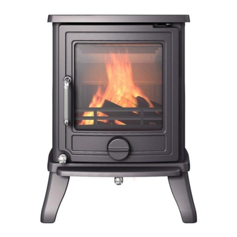
Newman FLAME VIEW ST1 User guide

Units 2, 6 & 7 Rawreth Barns,
Dollymans Farm,
Doublegate Lane,
Wickford,
Essex.
SS11 8UD
FLAME VIEW ST1 GAS STOVE
THIS APPLIANCE IS CATEGORY I2H FOR USE
WITH NATURAL GAS AT A SUPPLY PRESSURE
OF 20 mbar
G.B.
INSTALLATION & SERVICING BOOK
THIS MANUAL MUST BE LEFT WITH THE
USER
1
ISSUE 5

2
SECTION
CONTENTS
PAGE
1.0 APPLIANCE INFORMATION 3
1.1 CONDITIONS OF INSTALLATION 3
1.2 FLUE AND CHIMNEY SUITABILITY 3-4
2.0 INSTALLATION 5
2.1 HEARTH 5
2.2 SITING 5
2.3 FLUE CONNECTION 5
2.4 VENTILATION 5
2.5 GAS CONNECTION 6
2.6 FUEL FITTING 7-8
2.7 OPERATING INSTRUCTIONS 9-10-11-12
2.8 SPILLAGE 13
2.9 CUSTOMER EDUCATION 13
3.0 SERVICING INSTRUCTIONS 13
3.1 REPLACEMENT PARTS 13
4.0 CERAMICS HEALTH AND SAFETY 14

3
1. Appliance information
Model FLAME VIEW
Gas type G20 (natural gas)
Supply pressure (measured at test elbow), mbar 20
Injector (x1) Stereomatic 500
Oxypilot type Erta PG-82 -330 A14
Nominal Heat Input (Qn), kW (Gross)-Maximum Rate 5.1
Gas consumption at max rate (m3/h) 0.526
Minimum heat input kW (Gross) 2.9
Gas consumption at minimum rate (m3/h) 0.300
Gas connection 8mm compression
Remote gas valve TESCO1 RF868-15
Countries of Destination GB
Efficiency class 1
NOX 130 mg/kWH
The stove is a very heavy appliance and care must be used when lifting and moving, we recommend 2 people lift
following Health and Safety lifting guidelines.
Preferably wear suitable gloves and steel toe capped footwear when lifting and installing.
Please read all these instructions before commencing installation, maintenance,
and servicing.
1. Conditions of installation
Before installation, check that the local distribution conditions, nature of the gas and pressure, and adjustment of the
appliance are compatible.
It is the law that only a competent person installs all gas appliances i.e., a gas registered installer in accordance with the
current edition of the gas safety (installation and use) regulations or the rules in force. Failure to do so could lead to
prosecution.
The installer must be gas safe registered
The installation must also be in accordance with all relevant parts of the local and national buildings regulations where
appropriate, the building regulations (Scotland consolidation) issued by the Scottish development department, and all
applicable requirements of the following standard codes of practice:
1. BS 5871 part 1
2. BS 6891 installation of gas pipework
3. BS 5440 parts 1 & 2 installation of flues and ventilation
4. BS 8303 installation of domestic heating appliances
5. Is 813 domestic gas installation (republic of Ireland)
No purpose made additional ventilation is normally required for this appliance when installed in G.B.
if installing in Northern Ireland please consult local building regulations
In Scotland, please consult the current edition of the building standards regulations, issued by the
Scottish executive. Any purpose made ventilation must be checked periodically to ensure that it is
free from obstruction.

4
1.2 Flue & chimney suitability
This appliance is designed for use with conventional brick built or lined chimneys all flues must
conform to the following minimum dimensions
Minimum dimension of flue 125 mm Diameter.
Minimum effective height of all flue types 3 metres
Before commencing installation, a flue or chimney should be inspected to ensure that all of the
following conditions are satisfied.
1. Check that the chimney / flue only serves one fireplace and is clear of any obstruction,
any dampers or register plates must be removed or securely locked in the open position.
2. Brick / stone-built chimneys or any chimney or flue which has been used for an appliance
burning fuel other than gas must be thoroughly swept.
3. Any under floor air supply to the fireplace must be completely sealed off.
4. Ensure that the inside of the chimney / flue is in good condition along its length and check
that there is no leakage of smoke through the structure of the chimney / flue during and after
the smoke pellet test.
5. Using a smoke pellet check there is an updraft in the chimney / flue and that the smoke can
be seen coming from the terminal / pot outside.
There must be no leakage of smoke through the structure of the chimney during or after the
smoke pellet test and it is important to check the inside upstairs rooms adjacent to the chimney /
flue.
Check the chimney pot / terminal and general condition of the brickwork and masonry. if the
chimney / flue is in poor condition or if there is no up-draught do not proceed with the installation,
IIIIf there is a history of down draught conditions with the chimney / flue, a tested and certificated
flue terminal or cowl suitable for the relevant flue type should be considered.
6. A spillage test must always be carried out during commissioning of this appliance
REAR OF STOVE
OKE MATCH
SM

5
WARNING
This stove is fitted with a spillage monitoring system consisting of a thermal switch, which shuts
the appliance off in the event of a blocked flue or inadequate flue pull occurring. The system shall
not be adjusted by the installer or shall not be put out of action. When the spillage monitoring
system is required to be replaced, only original manufacturers parts shall be used.
If the stove switches off for no apparent reason, the appliance should not be used until expert
advice is obtained and the fault rectified.
All surfaces, except the control valve, are working surfaces and become very hot in use. They
must not be touched, or any combustible materials put on them
It is recommended that a fireguard complying to BS 8423 should be fitted for protection of young
children or elderly or infirm persons.
The door must be opened to remove the glass, allow to cool before removing this as it will
become very hot and is a working surface in use.
2.0 INSTALLATION
2.1 HEARTH
The stove must be installed on a non-combustible hearth with the hearth material being at least
12 mm thick the hearth must protrude at least 150 mm (6”) in front of the stove and be of a size
sufficient to accommodate the stove.
2.2 SITING
The stove must not be installed in a bathroom.
Clearance from non-combustible material in the fireplace opening must be at least to the
dimensions in the table below.
Position Non-combustible material Combustible material
Distance mm
Above 100mm 300mm
Back 50mm 300mm
Left 100mm 300mm
Right 100mm 300mm
Fitting the stove any closer to the back and sides may cause Nuisance shutdown of the stove as the
airflow may be compromised and the thermal cut off will operate.

6
2.3 FLUE CONNECTION
The flue should be at least 3m high and at least 125 mm diameter (5”) at no point should there be any
negative or horizontal gradients in the flue pipe.
It is recommended that a minimum height of 600mm from the stove before any significant change of
direction of the flue.
2.4 VENTILATION
Ventilation should be in accordance with national regulations in the UK purpose provided ventilation
is not normally required BS5871 part 1 and in IE IS813 (IE only)
2.5 GAS CONNECTION
The gas connection can be made by removing the glass including the retaining frame and seal by
removing the bolts holding it in place once removed the 4 bolts holding the burner in place can be
removed and access to the gas inlet elbow can be gained, once the connection is made and
soundness verified the burner can be replaced ensuring correct position and the 4 bolts then
replaced.

7
2.6 Placement of the ceramic logs
The logs should be positioned as in the pictures below.
WARNING: do not change the fuel bed layout, the type or number of logs
Completely fill the burner with
the mica supplied
Ensure if any spills into pilot it
is removed
Do not use appliance without
the mica in the burner
Rear log sits as shown to left
fully back
Front log sits to the front as
shown on left
Ensure the pilot light is visible
Left log sits as shown to left

Right log sits to right as shown
in picture on left
Log sits on the fuel bed and
rests on front log
As shown to left
Branch log sits on front log and
rear log as shown on left
Final log sits on front log and
Small amounts of glowing
flames come up show with X on
picture left & small Chipping’s
can cover metal for de
8
coration
but not on the burner
rests on branch log as shown
embers can be place where the

9
2.7
OPERATING INSTRUCTIONS
Below – the gas controls, which are situated at the bottom, left of the appliance
Below – remote control handset

10
Replacement of batteries in TESCO1 gas control
The TESCO1 gas controls which operate the appliance are battery powered and require replacing
periodically after removing the plastic front cover from the control, the batteries are fitted and
positioned as shown below , always replace the plastic cover once batteries have been fitted
Replacement of batteries in handset
The handset also has batteries as shown below. It is important that the batteries are replaced at least
every 12 months
The meaning (s) of the red indicator on valve and handset
Red indicator Meaning
Permanently Lit Valve tried to light but failed and in LOCKOUT E00
Flashing very fast Valve is busy (will not accept any command )
Flashing once a second Valve detects an error
Permanently off valve in standby or in a stable operation
On momentarily after power up valve doing a self-test
Appears after pressing start indicates time to release pressing the start button

11
Below information only the handset will already be paired
Pairing the handset with the gas valve
Ensure the handset and the gas fire control have good batteries inside and the batteries are
facing the correct direction (as shown inside the battery compartments).
Ensure the battery contacts and compartments are clean and free from any contamination.
(The green light on the handset will flash fast when the handset is held (not steady green),
which shows it is ready to accept a pairing from the gas fire control.
(NOTE: Ensure the small slide switch on the top left of the gas fire control is slid to the right
(I) position).
Place the handset within a few feet of the fire ( no need to hold it at the time ).
On the gas fire, simultaneously press the hold the - and + buttons on the gas fire control
(i.e. not the handset) unit the red light on top left of gas fire control begins to flash rapidly,(this
will take about 5-8 seconds), then immediately as the red light starts to flash release the -
and + buttons and quickly and press the power button that is underneath them. (Note: This
button press must be done with 1 second of the red light coming on. If not done quickly
enough, then the above must be repeated until done correctly).
When done correctly, you will hear an audible sound from the handset. Immediately pick up
and grasp the handset as normal to unlock the keypad and then press and hold the “ set “
button for around 3 to 5 seconds.
When you hear several beeps from the handset as the pairing has been confirmed.
You know the pairing has taken as now when holding the handset, the green light will be a
steady green ( not flashing when held).
You can now scroll through the settings of the handset adjusting by pressing + or - to adjust
each setting and move on when set by pressing the set button once all set keep pressing the
set button until you leave the set-up menu
More information can be found at www.crystalfires.co.uk
IMPORTANT USER INFORMATION – AFTER INSTALLATION BY THE ENGINEER , READ
THIS BEFORE ATTEMPTING TO OPERATE THE FIRE
NOTE: The handset is supplied paired to the Gas Control. Do not alter the pairing. The
handset is designed to be not too easily operated by accident for safety reasons. If for
any reason the pairing has been altered, then the handset will not work. The handset
needs to be reset and paired again.

Hold the handset as shown, wrapping your
hand around the handset touching both
sides. In a second or less the green unlock
light will illuminate, allowing the buttons
to work when pushed.
(NOTE: If the green light is not a constant
green or not lit at all the buttons will not
be operable).
Press and hold in the power symbol
button and release immediately when the
word pilot comes on to the display at the
bottom left as shown (about 1-2 seconds).
The stove will light.
(NOTE: Releasing too soon or too long
after the pilot illumination, results in the
Iire not lighting, this is for safety reasons).
To adjust high and low whilst holding the handset and green light on press + & -
to adjust preferred setting
To Stop the stove, hold handset to unlock the buttons and then press the 1
p
2
ower
button. The flame stops almost immediately.

2.8 SPILLAGE
CHECK FOR CLEARANCE OF COMBUSTION PRODUCTS
CLOSE ALL DOORS & WINDOWS IN TH E ROOM CONTAINING THE APPLIANCE.
TURN ON APPLIANCE AND TURN TO HIGH, LEAVE RUNNING FOR 5 MINUTES AND
INSERT A LIGHTED TAPER OR SMOKE MATCH INTO THE FLUE DIVERTER AT THE REAR
OF THE APPLIANCE
ALL THE SMOKE MUST BE DRAWN INTO THE APPLIANCE.
IF SPILLAGE OCCURS ALLOW A FURTHER 10 MINUTES AND RETEST.
SHOULD SPILLAGE OCCUR SEEK EXPERT ADVICE.
IF AN EXTRACTOR FAN IS SITUATED IN THE ROOM THE TEST SHOULD BE CARRIED
OUT WITH THE FAN RUNNING IF THERE IS A CONNECTED ROOM WITH AN
EXTRACTOR FAN THE TEST SHOULD BE REPEATED WITH THE FAN RUNNING AND ANY
INTERCONNECTING DOORS OPEN
REAR OF STOVE
OKE MATCH
2.9 CUSTOMER EDUCATION
Hand these instructions to the user.
Advise the user until they are fully educated on the use of the stove and the controls.
Explain regarding the thermal cut off feature.
Advise if this system repeatedly shuts off specialist advice must be consulted
.Advise that if the fire goes off for any reason do not re light for 3 minutes.
Advise the stove may give off a slight smell due to the newness and any odors will go after a few hours of use.
Advise that the stove must not be used with the glass panel damaged or broken or missing.
Advise that no materials like washing, may not be draped over the stove
Recommend regular servicing at least annually.
Recommend no extra fuel pieces are added and only authorised spares are used.
3.0 SERVICING INSTRUCTIONS
The stove is fitted with a spillage monitoring system consisting of a thermal switch this system is not
adjustable and must not be bypassed or put out of action if any parts are replaced it must be with the original
manufacturers parts used.
1. Servicing must be carried out regularly and only by a qualified person, ensure the fire is turned off and
cold (minimum service must be carried out annually)
2. Open the stove door. The bolts holding the glass can be removed and the glass panel with frame & seal
removed.
3. Remove the ceramics carefully
4. Remove any debris from the burner if necessary, using a suitable vacuum also clean the pilot or vacuum.
5. If necessary, replace pilot (for extended warranty) by removing the burner and disconnect gas supply 4
screws can be removed and burner tray removed the thermal cut off switch will have to be disconnected at
the rear of the fire to allow the tray to be removed it has to be lifted up on the right-hand side and carefully
twisted out.
6. Replace burner tray and reconnect thermal switch the appliance will not work if this is not done and then
replace in reverse order replace glass and close the stove door.
7. Check the supply pressure and test for spillage
8. The flue will need sweeping periodically for safe use of the appliance.
3.1 REPLACEMENT PARTS
SM
PILOT ASSEMBLY
ERTA-PG-82-330 A14
THERMAL SWITCH TSC-30112010AFV
THERMAL SWITCH WIRES TTB WIRES
FUEL LOGS
INJECTOR STEREOMATIC 500
HANDSET TESC DISPLAYHANDSET
VALVE TESCO1 RF868-15

14
4.0 Ceramics Health and Safety
Newman Ceramic logs and fuel bed for FlameView STI gas stove
This appliance could contain some of the materials, indicated below, that could be
interpreted as being injurious to health and safety. It is the users/installers
responsibility to ensure that the necessary personal protective clothing is worn when
handling these materials, see below for information.
Artificial Fuels, Mineral Wool, Insulation Material, Refractory/CeramicFibres,
Glass Yarn may be harmful if inhaled, may be irritating to skin, eyes, nose, and throat.
When handling avoid inhaling and contact with skin or eyes. Use disposable gloves,
facemasks, and eye protection. After handling wash hands and other exposed
parts. If a vacuum is used for cleaning any ceramic fuel bed parts including logs
and chippings etc it is recommended that it be of the type fitted with a HEPA filter.
Disposal of refractory/ceramic materials. To keep dust to a minimum
these materials should be securely wrapped in polythene and be clearly
labelled ‘RCF waste.’ RCF will be a 'special waste' and will need to be disposed
of accordingly, i.e., with a consignment note and at a licensed disposal site.
For further information contact the local Environment Agency office (SEPA
in Scotland).
Do not let children touch any ceramic part.
Do not get any ceramics wet.
Do not cut or break any ceramics
Table of contents
Other Newman Stove manuals
Popular Stove manuals by other brands
Primus
Primus 3244 Instructions for use

Napoleon
Napoleon Arlington GDS20N Installation and operating instructions

Lotus
Lotus Mondo Series Mounting and user instructions
Enviro
Enviro M-55-FS Technical manual

Palazzetti
Palazzetti CLEMY Instructions for use and maintenance

Leenders
Leenders Oris 46000 user manual
Arada
Arada Ecoburn S3 Fittings guide

Easylife
Easylife EL6300 instruction manual
Drolet
Drolet DB04815 Installation and operation manual
Miele
Miele KM 2050 Instructions for installation and use

Nobis
Nobis A9 V/C ZENITH Instructions for installation, use and maintenance manual
wallas
wallas SafeFlame 96 D manual
