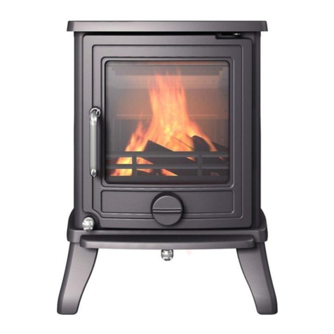
Newman Windermere 5 SE Assembly Instructions

Windermere 5 SE
Smoke exempt multi fuel burning stove.
Installation & user instructions.
(To be left with customer).
Edition 1
Reference: NS-24
Date: 22/09/2021

2
Index
Page. Section.
3 - 4 1.0 Pre-installation checks & general safety notes. Clean Air Act
1993 & smoke control areas. HETAS Ltd Approval.
3 – 4 1.1 Pre-installation checks & general safety notes
4 1.2 The Clean Air Act 1993 and Smoke Control Areas
4 1.3 Hetas Ltd approval
5 - 6 2.0 Technical and emission data.
7 - 26 3.0 Installation
7 3.1 Unpacking the stove
7 3.1.1 Installing the stove
7 3.1.2 The tertiary air control
8 - 12 3.1.3 Assembling the baffle and removable internal stove parts
13 3.1.4 Removal of the outside air feed connection
14 3.2 Stove data plate position
15 - 18 3.3 Stove placement / clearance requirements
18 - 19 3.4 The chimney
19 - 21 3.4.1 Stove pipe connection
22 3.4.2 Connecting to a masonry chimney
22 3.4.3 Connecting to a stainless-steel twin wall insulated flue system
23 3.5 Ventilation (Fresh air supply)
24 3.6 Chimney draft
25 3.7 Carbon Monoxide Alarm
25 - 26 3.8 Commissioning and handover.
27 - 53 4.0 User Manual
27 - 31 4.1 Warnings and Safety
32 - 33 4.2 Maximum fuel loads and Recommended fuel
34 - 37 4.3 General use & operation
37 - 38 4.3.1 Use with wood
39 4.3.2 Use with approved smokeless fuel
40 - 41 4.3.3 Ash removal, disposal of ash & cleaning the main grate
42 - 46 4.4 Maintenance
43 - 44 4.4.1 Replacing the glass panel & rope seal
44 - 45 4.4.2 Replacing the door rope seal
45 - 46 4.5 User cleaning and maintenance.
45 4.5.1 User Maintenance Safety Warnings
45-46 4.5.2 Cleaning glass. (User)
46 4.5.3 Cleaning and checks inside the firebox. (User)
46 4.5.4 External surface cleaning. (User)
47 - 51 4.6 Operational problems – troubleshooting
51 4.7 Replacement parts and modifications
51 4.8 Product End-of Life / Recycling
52 - 53 4.9 Exploded view of stove parts and identification
54 - 56 5.0 Declaration of Performance, Energy Label & Product Fiche
54 5.1 Declaration of Performance
55 5.2 Energy label
56 5.3 Product fiche

3
1.0 Pre-installation checks, general safety notes.
Clean Air Act 1993 & Smoke Control areas.
HETAS Ltd approval.
1.1 Pre-installation checks & general safety notes
Installation of this stove must be completed in accordance with current local codes and
Regulations in each country. All local Regulations & any Rules in Force, including those
which refer to National and European standards, must be observed when installing this
product.
Reference must be made to current issues of British Standard BS 8303, code of practice for
installation of domestic heating and cooking appliances burning solid mineral fuel and BS EN
15287-1:2007 design, Installation, and Commissioning of chimneys.
Note: It is a legal requirement under England & Wales Building Regulations that the
installation of this stove is undertaken under Local Authority Building Control or is installed
by a competent person registered with a Government Approved Competent Persons Scheme.
Hetas Ltd operate such a scheme and a listing of their registered Competent Persons can be
found on their website at www.hetas.co.uk
Should any conflict occur between these instructions and any current Regulations and Rules in
Force then the Regulations and Rules in force must apply.
An approved Carbon Monoxide alarm conforming to the latest edition of BS EN 50291 must
be installed into the room into which the stove is installed. Installation and positioning must
be in accordance with current National Building Regulations & any Rules in Force including
(Approved Document J. England & Wales). Also refer to alarm manufacturer's instructions.
This stove must not be installed into a flue that shares any other appliance.
Extractions fans or units must not be installed into the room of stove installation.
The installer has a responsibility to ensure that all requirements of Health & Safety at Work
Act are observed & implemented as stated on the date of installation.
Due to the weight of this stove adequate facilities must be available for loading, unloading &
installation.
Always ensure that there is an adequate air supply into the room containing the stove.
It is very important that flue ways are regularly swept & checked by an approved person. It is
recommended that sweeping and checking should be done at least twice each year for
approved smokeless fuel use and quarterly each year for wood burning. The installer must
ensure that the chimney is examined for soundness and suitability before the appliance is
installed. Remedial action should be taken if required, seeking expert advice if necessary.
Where the chimney is believed to have previously served an open fire installation it is possible
that the higher flue gas temperatures from a closed appliance may loosen deposits that were
previously firmly adhered, with the consequent risk of flue blockage. It is therefore
recommended that the chimney be swept a second time within a month of regular use after
installation.
All dampers or restrictors must be removed from the flue.
This stove must be maintained to ensure safe operation & efficiency.
Only use this appliance for domestic property heating in accordance with these instructions.
This appliance is not suitable and must not be installed to any type of water vessel.

4
Fire cement can be caustic & should not be allowed to come into contact with skin. Refer to
manufacturer’s instructions.
This stove contains no asbestos. If there is any situation or possibility of disturbing any
asbestos during installation seek professional advice.
An installation / user manual is enclosed with this product. The installation can only be used
after it has been inspected by a qualified inspector. A name plate of heat-resistant material is
affixed to this product. This contains information about identification and documentation for
the product.
1.2 The Clean Air Act 1993 and Smoke Control Areas
Under the Clean Air Act local authorities may declare the whole or part of the district of the
authority to be a smoke control area. It is an offence to emit smoke from a chimney of a
building, from a furnace or from any fixed boiler if located in a designated smoke control area.
It is also an offence to acquire an "unauthorised fuel" for use within a smoke control area
unless it is used in an "exempt" appliance ("exempted" from the controls which generally
apply in the smoke control area).
The Secretary of State for Environment, Food and Rural Affairs has powers under the Act to
authorise smokeless fuels or exempt appliances for use in smoke control areas in England. In
Scotland and Wales this power rests with Ministers in the devolved administrations for those
countries. Separate legislation, the Clean Air (Northern Ireland) Order 1981, applies in
Northern Ireland. Therefore, it is a requirement that fuels burnt or obtained for use in smoke
control areas have been "authorised" in Regulations and that appliances used to burn solid fuel
in those areas (other than "authorized" fuels) have been exempted by an Order made and
signed by the Secretary of State or Minister in the devolved administrations.
Further information on the requirements of the Clean Air Act can be found here:
http://smokecontrol.defra.gov.uk/
Your local authority is responsible for implementing the Clean Air Act 1993 including
designation and supervision of smoke control areas and you can contact them for details of
Clean Air Act requirements."
To ensure smokeless operation opertate the stove in accordance with these instructions.
(Please see instructions within this manual).
The Windermere 5 SE have been recommended as suitable for use in smoke control areas when
burning wood.
The Windermere 5 SE must be fitted with a permanent stop to prevent closure of the secondary
air control beyond 10.5mm open and the tertiary air control beyond 12.5mm open.
The appliance is only exempt when used in accordance with these instructions.
1.3 HETAS Ltd approval
The Windermere 5 SE appliance has been approved by HETAS Ltd as an intermittent operating
appliance for burning wood logs.

5
2.0 Technical and Emission data.
Windermere 5 SE
Material: Cast iron and steel.
Finish: High-temp resistant paint.
Fuel: Wood (Approved wood logs)
Approved Smokeless Fuels (Maxibrite used for tests)
Log length: 30cm maximum
Flue outlet: Top or rear
Flue pipe dimension: Internal diameter 125mm / 122.7cm2 cross section
Approx. weight: 80kgs
Dimensions, distances etc: Figure 2 & 2A
Technical data according to EN 13240+A2:2004.
Fuel: Approved wood logs
Nominal heat output: 5.0kw
Flue gas mass flow: 3.8 g/sec
Recommended chimney draught: 12.5 Pa
Net Efficiency: 81.3 %
Verified Seasonal Efficiency: 71.3%
CO emission (13% O2): 0.11%
Mean flue gas temperature, at date of test: 274 0C
Operational mode: Intermittent

6
Emission data.
Mean CnHm emission @ (13% 02), mg/Nm3 90 Nmg/m3
Mean CO emission @ (13% 02), mg/Nm3 1354 Nmg/m3
Mean NOx emission @ (13% 02), mg/Nm3 97 Nmg/m3
Din Plus particulates @ 13% 02: 930mg/Nm3 10 Nmg/m3
Technical data according to EN 13240+A2:2004.
Fuel: Approved Smokeless fuels (Maxibrite used for tests).
Nominal heat output: 5.0kw
Flue gas mass flow: 4.4 g/sec
Recommended chimney draught: 12.5 Pa
Net Efficiency: 77.4 %
Verified Seasonal Efficiency: 67.4%
CO emission (13% O2): 0.11%
Mean flue gas temperature, at date of test: 280 0C
Operational mode: Intermittent
Emission data.
Mean CnHm emission @ (13% 02) mg/Nm3 17 Nmg/m3
Mean CO emission @ (13% 02), mg/Nm3 1375 Nmg/m3
Mean NOx emission @ (13% 02) mg/Nm3 107 Nmg/m3
Din Plus particulates @ 13% 02: 930 mg/Nm3 18 Nmg/m3

7
3.0 Installation
3.1 Unpacking the stove
Warning:
Due to the weight of this stove (80kg) we recommend that at least 2 people will be required.
Adequate facilities must be available for loading, unloading & installation.
Ensure before unloading this appliance that all routes to the installation site are safe, well-lit, un-
obstructed and all people and animals are completely clear and safe of the delivery route. All
relevant Health and Safety regulations must be observed.
Ensure that any surface or floor can support the weight of the stove, installers & equipment before
attempting to unload and deliver the stove.
Before unpacking the stove, it is important to identify the stove door incorporating the ceramic
glass window position to avoid damage, you will find a label on the packaging that informs the
side the ceramic glass is facing.
Remove the straps that hold the ply box together.
Pull the ply box upwards until clear of the stove.
Remove the plastic and cardboard glass protector packaging.
Open the door and remove paper protection between the door and stove face.
Remove the glass internal ply protector.
Remove the instructions, Energy labels, Cardboard box that contains the flue collar adaptor, stove
mitten and ash pan / operating tool plus all silica moisture absorbing sachets.
After removing the outer packaging, remove the combustion chamber from the wooden pallet and
place it gently on its feet onto a level weight bearing floor. Note: There are lower bolts supplied
for fitment into holes in the base of each leg, these are adjustable to allow level adjustment of the
stove to uneven surfaces.
The instruction manual, Energy label, Energy fiche, Stove tools, and Stove mitten to be given to
the user after installation and explanation of stove use.
Dispose all packaging & Silica sachets. Always dispose of items in a way that is sustainable as
possible and that is in line with the current environmental protection, reprocessing / recycling, and
disposal technology.
3.1.1 Installing this stove
The stove and chimney installations must comply with all Current National and Local Building
Regulations and any Rules in Force including current issues of British Standard BS 8303 code of
practice for installation of domestic heating and cooking appliances burning solid mineral fuel and
British Standards BS EN 15287-1:2007 design, installation, and commissioning of chimneys; your
approved dealer or your local building control officer can advise regarding this. Ultimately, it is
you and your installer who is responsible to ensure that the installation complies with all relevant
Regulations and any Rules in Force.
For installations within England and Wales also refer to the Current Approved Document J that
gives guidance on complying with the Building Regulations.
3.1.2 Tertiary air control
The Tertiary air intake is a standard part for the Windermere 5 SE stove, there is no control to the
tertiary air intake as it is set to 100% open at manufacture.

8
3.1.3 Assembling the baffles and removeable internal parts.
See figures 1 to 1.7
All stove internal parts are assembled at manufacture, however with movements and handling
during stove delivery it is possible that some or all the located parts inside the stove may have
moved, therefore it is important to check all these parts for correct position and fitment after the
stove is located. Check the 2 baffles and all other parts are located into correct positions including
side bricks, back brick, main grate, banking bar and ash pan. Before lighting the stove for the first
time, confirm the baffle and all parts are in correct location.
Location of non bolted stove internal parts.
See Figure 1
Drawing of parts that are not bolt fixed to the inside of stove that may have moved during
transportation. These parts must be checked to ensure they are in correct location before lighting
the stove.
Fig 1

9
Fig 1.1 Main grate positioning.
Fig 1.2 Top steel baffle positioning.

10
Fig 1.3 Top (lower) vermiculite baffle positioning.
Fig 1.4 Left & right-hand side brick positioning.
Note: The vermiculite lower baffle will require to be raised to the front edge to allow the side
bricks to be installed against the internal sides of stove after which the lower baffle is lowered into
correct position on top of both side bricks.

11
Fig 1.5
Side view showing:
Top steel baffle, Top (lower) vermiculite baffle, Rear vermiculite back brick, Vermiculite side
bricks, Banking bar, Main grate & Ash pan positions.
The red text and arrows show the sequence of positioning the top (lower) baffle into correct
position also refer to figures 3 & 4

12
Fig 1.6 Banking bar positioning.
Fig 1.7 Ash-pan positioning

13
3.1.4 Removal of the air intake assembly for external air supply.
See figure 1.8
As there are no current approvals offered by the test institutes for outside direct air feed
connections therefore this facility must not be used and removed from the stove. The air feed for
this stove uses room ventilation as section: 3.5 Ventilation (Fresh air supply):
1) Remove the lower heat shield by removing the 4 retaining nuts.
2) Remove the 4 bolts securing the air intake assembly and remove from the stove.
3) Replace the lower heat shield securely using the 4 retaining nuts.
4) Check that all parts within the stove have not moved and are in the correct positions.
Fig 1.8

14
3.2 Stove Data plate position.
See figure 1.9
Figure 1.9 shows the position of the stove data plate which is located to the rear of the stove. This
shows important information, including:
a) Model
b) Standard number
c) Production date
d) Dimensions
e) Serial number
f) Weight
g) Recommended fuel
h) Co Emissions
j) Efficiency
k) Nominal heat output
l) Notice showing minimum distance to combustibles and other safety notes
m) Manufacturers details
Fig 1.9

15
3.3 Stove placement / clearance requirements
This stove must only be installed onto floors with an adequate load-bearing capacity. If an
existing construction does not meet this requirement, suitable measures (e.g., load distributing
plate) must be taken and must be in accordance with Current National laws, Building Regulations,
& any Rules in Force, including BS 8303 and BS EN 15287-1:2007. Also refer to (Approved
Document J England & Wales)
Wooden floor protection. See: Figure 2 and 2A
The Windermere 5 SE stove can only be used with a Constructional hearth and Superimposed
hearth, the superimposed hearth must be a minimum of 400mm in front of the stove all other
dimensions and specifications must be in accordance with Current National laws Building
Regulations, & any Rules in Force, including BS 8303 and BS EN 15287-1:2007. Also refer to
(Approved Document J England & Wales).
Minimum distance between the stove and a wall made of combustible material
See: Figure 2.
To the right-hand side of stove 550mm
To the left-hand side of stove 550mm
To the rear of stove 450mm
Also refer to: Current National laws, Building Regulations, & any Rules in Force, including BS
8303 and BS EN 15287-1:2007 & (Approved Document J England & Wales).
Contact your local building authority regarding restrictions and installation requirements.

16
Minimum distances between stove and a conventional brick Class 1 Chimney.
See: Figure 2A
Refer to Current National laws, Building Regulations, & any Rules in Force, including BS 8303
and BS EN 15287-1:2007 & (Approved Document J England & Wales).
When installing this stove into a conventional class 1 non combustible brick chimney built to
Current National laws, Building Regulations and any Rules in Force including BS 8303 and BS
EN 15287-1:2007 the clearances between the stove and non-combustible chimney must comply
with Current National laws, Building Regulations & any Rules in Force, providing all surrounding
non-combustible chimney brick walls have a minimum thickness of 200mm the clearance between
the rear & sides of stove can be reduced to 50mm, refer to Current National laws, Building
Regulations & any Rules in Force. However, it is recommended that the measurement between
the sides & rear of stove to be as large as possible above this dimension, as the efficiency of this
stove is dependent on the clearances as shown in figure 2A.
For all other clearances to a non-combustible brick wall and chimney refer to Current National
laws, Building Regulations, (Approved Document J England & Wales) & any other Rules in Force,
including BS 8303 and BS EN 15287-1:2007.
Contact your local building authority regarding restrictions and installation requirements.

17
It is recommended that if a suitable non-combustible fireplace such as stone / marble or other
non-combustible fireplace types is to be installed to accommodate this stove that the fireplace
supplier is contacted to see what recommended clearances are required between the stove and the
fireplace, although most natural stone and marble are non-combustible there is a possibility of the
stone or marble being damaged such as cracking if the stone or marble material is heated
excessively.
Ceiling protection.
Refer to: Current National laws, Building Regulations, & any Rules in Force, including BS 8303
and BS EN 15287-1:2007 & (Approved Document J England & Wales)
Clearances to furniture and soft furnishings
Serious consideration should be given to positioning of any furniture or soft furnishings that
could be adversely affected by heat. Newman Fireplaces Ltd recommend that any furniture or soft
furnishings or any combustible materials to be a minimum of 2000 mm away from the stove.
Never use or store aerosol sprays or any other combustible products in the vicinity of the stove
when it is in operation or whenever the stove is hot. The stove will remain hot for some time even
after the fire is extinguished.
When lit, a wood-burning stove gets hot and therefore adequate protection must be provided,
particularly in situations where there is a safety risk to children or the infirm. When using this
stove in situations where children, aged and / or infirm persons are present a fireguard

18
manufactured in accordance with BS 8423:2010 + A1: 2016 must be used and such persons must
be supervised at all times.
It is also recommended that all other people should use a fireguard in accordance with BS
8423:2010 + A1: 2016 at all times when the stove is alight or hot.
3.4 The chimney.
Refer to current National laws, Building Regulations, and any Rules in Force, including British
standard BS EN 15287-1:2007 and BS 8303 and (Approved Document J England & Wales)
The construction of the masonry chimneys, flue block chimneys and connecting flue pipe system
must meet the requirements of the Current National laws, Building Regulations, and any Rules in
Force.
This stove must never be connected to any shared chimney.
An efficient modern stove places heavy demands on the chimney, and you should have the
chimney regularly swept and inspected at least twice a year for smokeless fuel use and quarterly
for wood fuel use by an approved chimney sweep.
The flue or chimney system must be in good condition. It must be inspected and swept by a
competent registered person and passed for use with the appliance before installation. The
National Association of Chimney sweeps (NACS) and for Northern Ireland (NIACS) Northern
Ireland Association of Chimney Sweeps offer a register of approved chimney sweeping and
inspection services who will issue certificates after inspection and sweeping.
Where the chimney is believed to have previously served an open fire installation it is possible that
the higher flue gas temperatures from a closed appliance may loosen deposits that were previously
firmly adhered, with the consequent risk of flue blockage. It is therefore recommended that the
chimney be swept a second time within a month of regular use after installation by an approved &
competent chimney sweep.
If it is necessary to fit a register plate it must conform to the Current National laws, Building
Regulations, and any Rules in Force.
The minimum height of the flue or chimney must be 4.5m from the hearth to the top of the flue,
with no horizontal sections and a maximum of 4 bends. Bends must have angles of less than 45
degrees from the vertical. There should be at least 600mm of vertical flue pipe above the appliance
before any bends are introduced. Ensure the connecting flue pipe is kept a suitable distance from
any combustible material and does not form part of the supporting structure of the building.
The installer must ensure the flue pipe diameter is not less than the diameter of the outlet of the
appliance and does not narrow to less than the size of the outlet at any point in the system.
Make provision to remove the appliance without the need to dismantle the chimney.
Any existing flue must be confirmed as suitable for the new intended use as defined in the Current
Building Regulations.
The flue or chimney systems must be inspected and swept by an approved chimney sweep to
confirm the system is structurally sound and free from obstructions.
The flue exit from the building must comply with Current National laws, local building control
rules, Building regulations and any Rules in Force.
Chimney heights and / or separations may need to be increased in particular cases where wind
exposure, surrounding tall buildings, high trees or high ground could have adverse effects on flue
draught
It is highly recommended that an approved and certified flexible flue liner that complies with
Current National laws, Building Regulations and any Rules in Force of the correct internal

19
diameter be used to line the chimney, the liner must be approved for use with Multi Fuel burning.
Flue liner installation must comply with Current National laws, Building Regulations, and any
Rules in force, also refer to the flue liner manufacturer’s instructions. The flue liner must be
replaced when an appliance is replaced, unless proven to be recently installed and in good
condition.
The cross-sectional area of the chimney (at its narrowest point) must comply with Current
National and Local Building Regulations and any rules in force. Generally, the area needed for a
wood-burning stove installation should measure at least 150 mm internal diameter. Please refer to
Current National laws, Building Regulations, and any Rules in Force.
Important note: The Windermere 5 SE has been tested for smoke exemption so a minimum
internal flue diameter of 125mm can normally be used. *(This must be confirmed with HETAS or
Local Authority Building Control and all Current National laws, Building regulations and any
Rules in Force).
An over-sized chimney is generally hard to keep warm and results in poor draft. In cases where
there is an oversized masonry chimney, it is highly recommended that the chimney be lined using
an appropriate and approved chimney lining system with the correct internal diameter as stated
above.
With respect to the chimney termination, all chimneys must terminate in accordance with Current
National and Local Building Regulations.
Note: Current National and Local Regulations also apply with regard to the placement of
chimneys and flues in connection with thatched roofs.
The chimney or flue system must be equipped with access doors for inspection and cleaning. The
size of the cleaning door in the chimney must at least equal to that of the cross-sectional area of
the chimney. In the event that a chimney fire occurs resulting from faulty operation or prolonged
use of damp wood fuel, if safely possible close the air vents of the stove completely, evacuate all
persons from the building and contact your local fire department immediately.
3.4.1 Stove Pipe connection.
Refer to: Current National laws, Building Regulations, and any Rules in Force including BS 8303
and BS EN 15287-1:2007 and (Approved Document J England & Wales)
There are two stove flue exits enabling either top or rear venting depending on installation
requirements.
Check that the flue collar adaptor and flue blanking plate rope seals are not damaged and in correct
position. See figures 3.0, 3.1 & 3.2
Top flue exit position.
If using the stove top flue exit, un-screw and remove the 3 flange bolts supplied from the stove top
flue exit position.
Check that the flue collar adaptor rope seal is not damaged and in correct position.
Align the flue collar adaptor to the stove top flue exit position ensuring the 3 flange bolt hole
positions align with the 3 threaded holes to the stove top flue exit position.
Screw each bolt through each flue collar adaptor flange into the threaded holes within the stove
top, evenly tighten the 3 bolts so the flue collar adaptor is securely fastened to the top of the stove.

20
Rear flue exit position.
If using the rear flue exit position, remove the steel heat shield to the rear of stove by un-fastening
the 4 securing nuts, this will expose the rear flue blanking plate.
Un-fasten the 3 bolts securing the blanking plate and remove.
Check the flue blanking plate rope seal is in correct position and un-damaged.
Securely bolt the blanking plate to the stove top flue position as described above.
Securely bolt the flue collar adaptor to the stove rear exit flue position as described above.
Securely fasten the heat shield to the rear of stove using the 4 nuts supplied.
A suitably gauged metal rigid stove flue pipe of the correct size complying with Current National
laws, Building Regulations, and any Rules in Force (not supplied), is connected to the flue collar.
The joint between the stove collar and rigid stove pipe must be fully sealed using suitable stove
rope / fire cement. When the rigid stove flue pipe is fully inserted into the stove flue collar drill
two suitably sized holes in a suitable position 180 apart through the stove flue collar and rigid
stove pipe and use either corrosion proof self-tapping screws or bolts, nut and washers of suitable
size to ensure the rigid stove pipe is unable to be pulled out of the stove collar. Ensure the
self-tapping screw or bolt nut and washers do not obstruct the stove collar flue way and ensure the
screws or bolts and locating holes are airtight.
The chimney or flue way that the stove pipe is connected must be at least 125mm internal
diameter. (ii) rectangular or square flues having the same internal cross-sectional area and a
minimum dimension of 100mm for straight flues or 125mm for flues with bends or offsets. Refer
to Current National laws, Building Regulations, any Rules in Force including BS 8303 and BS EN
15287-1: (This must be confirmed with HETAS or Local Authority Building Control and all
National laws, Building regulations and any Rules in Force).
Fig 3.
Flue adaptor if using the top exit. Top exit blanking plate if using rear exit.
Table of contents
Other Newman Stove manuals
Popular Stove manuals by other brands

Morsø
Morsø 6840 Instructions for installation and use
SCAN
SCAN DSA 5 Instructions for installation and use

Comfort Glow
Comfort Glow ESQ5130 manual
Breckwell
Breckwell G29DV user guide
Capital
Capital SIRIUS TRADITIONAL Installation and operating instructions
Quadra-Fire
Quadra-Fire MTVERNON-AE-CSB owner's manual

Vermont Castings
Vermont Castings Vigilant II 2310 Brochure & specs
Morso
Morso DB15 Installation and operating instructions

Austro Flamm
Austro Flamm Scotty Duo operating manual
KEKAI
KEKAI KTL500 instruction manual

RIKA
RIKA TOPOII operating manual
AGA
AGA BERRINGTON NON BOILER Installation and operating instructions

