
8
15272 Newsboy Circle
Huntington Beach,
CA 92649
Phone: 714-751-0488
Fax: 714-372-7930
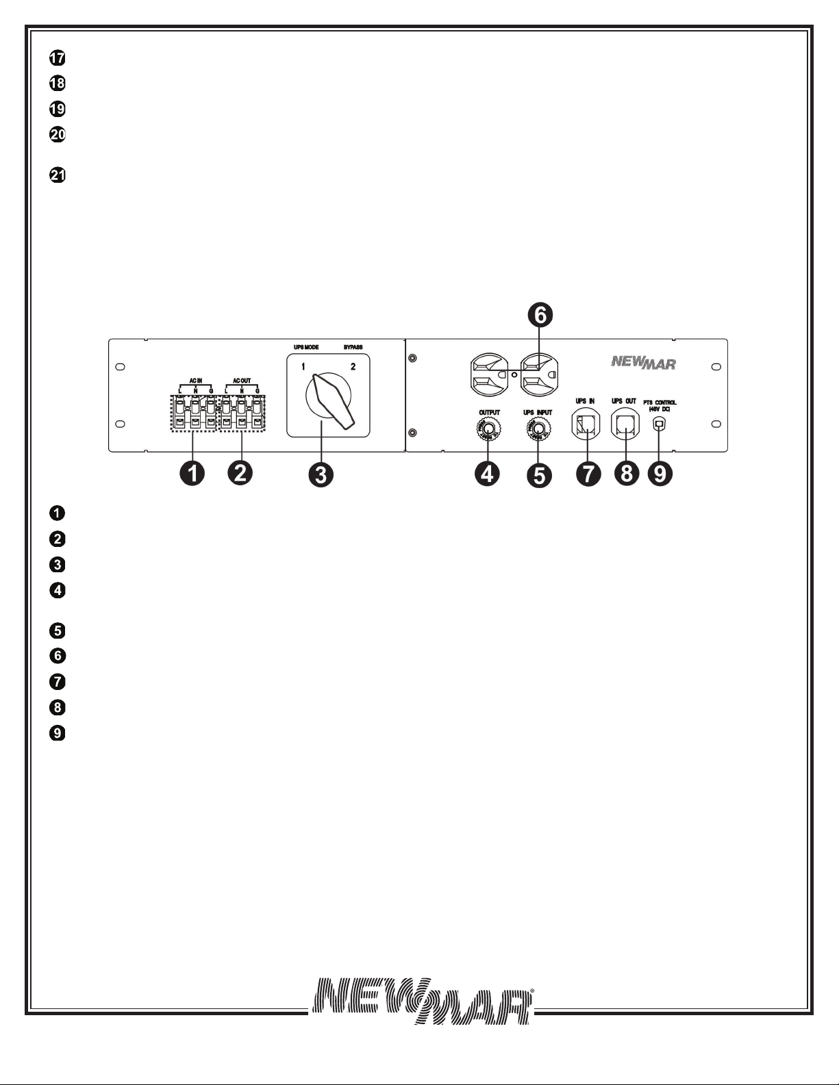
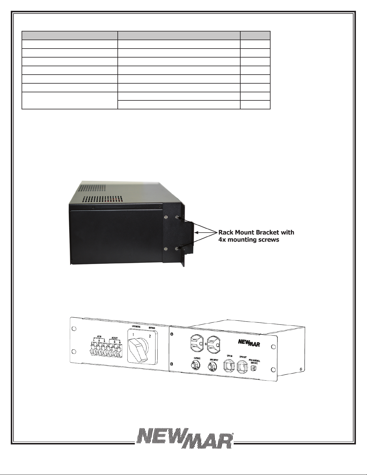
5. OPERATION
To power up the UPS, ensure the switch on MBS is in “UPS Mode” position. Before commissioning, make sure batteries are
fully charged and line power is qualified.
5.1 Switch on UPS in Line Mode
1. Switch the battery circuit breaker ON. All LEDs will illuminate and the LCD will display, the Startup page, and fan will
turn on.
2. Switch the AC input breaker ON. After line power is qualified, the LCD will display normal, buck or boost according to
line voltage range and line threshold setting.
Note: The AVR function default setting is disabled. You may activate it via the LCD panel or USB/RS232/SNMP communi-
cation.
5.2 Switch the UPS from Line Mode to Battery Mode
The UPS will operate in battery mode, if the input circuit breaker is manually switched OFF. The LCD will display Battery
and the output LED will flash and alarm LED will illuminate to show the UPS is running on backup battery power.
5.3 Switch from Battery Mode to Line Mode
After switching input circuit breaker ON and if the line input is qualified, the UPS will transfer to line mode with the output
LED “ON” to show UPS is running from utility power.
Note: If the UPS keeps switching between inverter and line mode because of a noisy line, the setting of “UPS Sense type”
should be changed from Normal or UPS to Generator.
5.4 Switch Off Procedure
For any reason you need to switch off UPS, please follow below procedure.
1. Switch the output circuit breaker OFF.
2. Switch the input circuit breaker OFF.
3. Switch the battery circuit breaker OFF. The output LEDs and the LCD display will shut off.
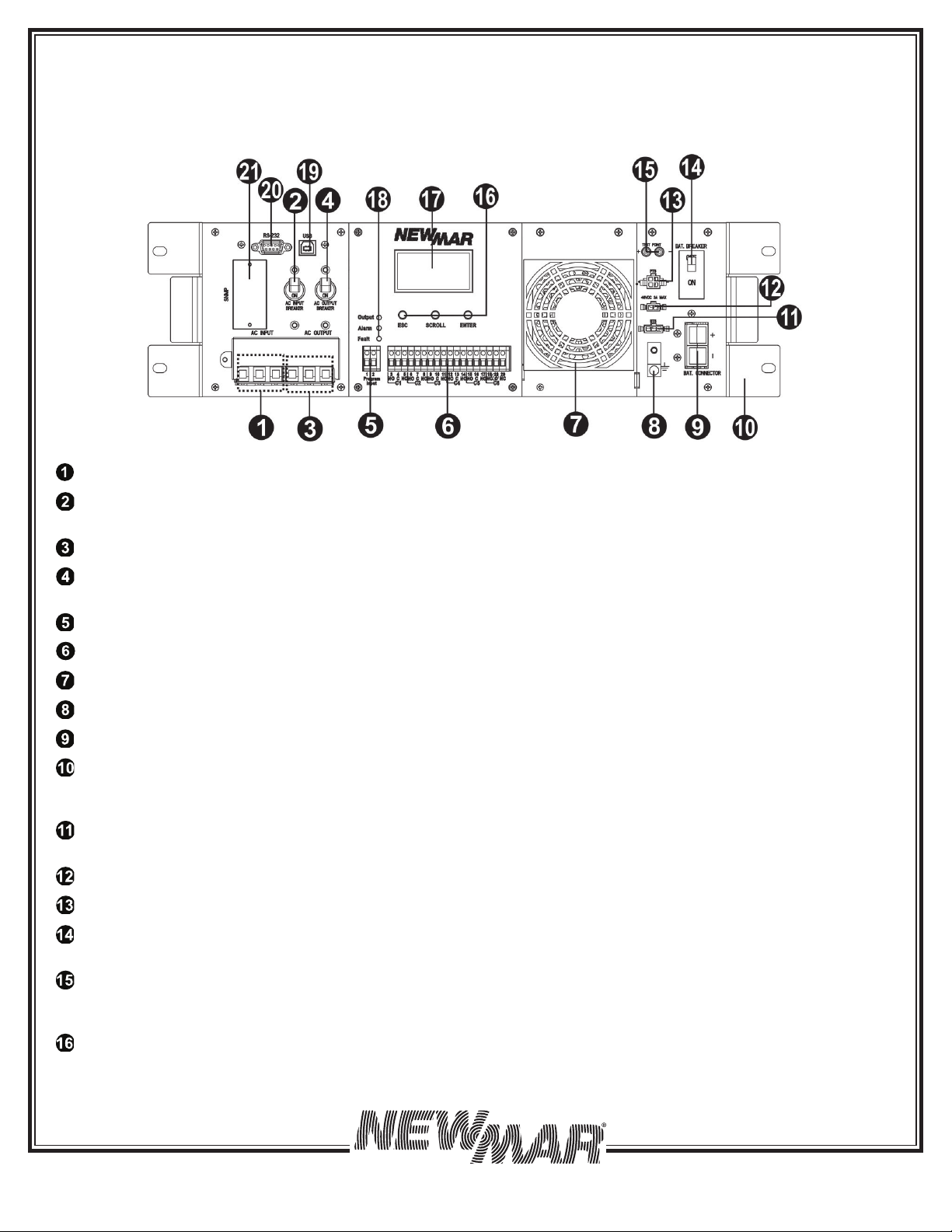
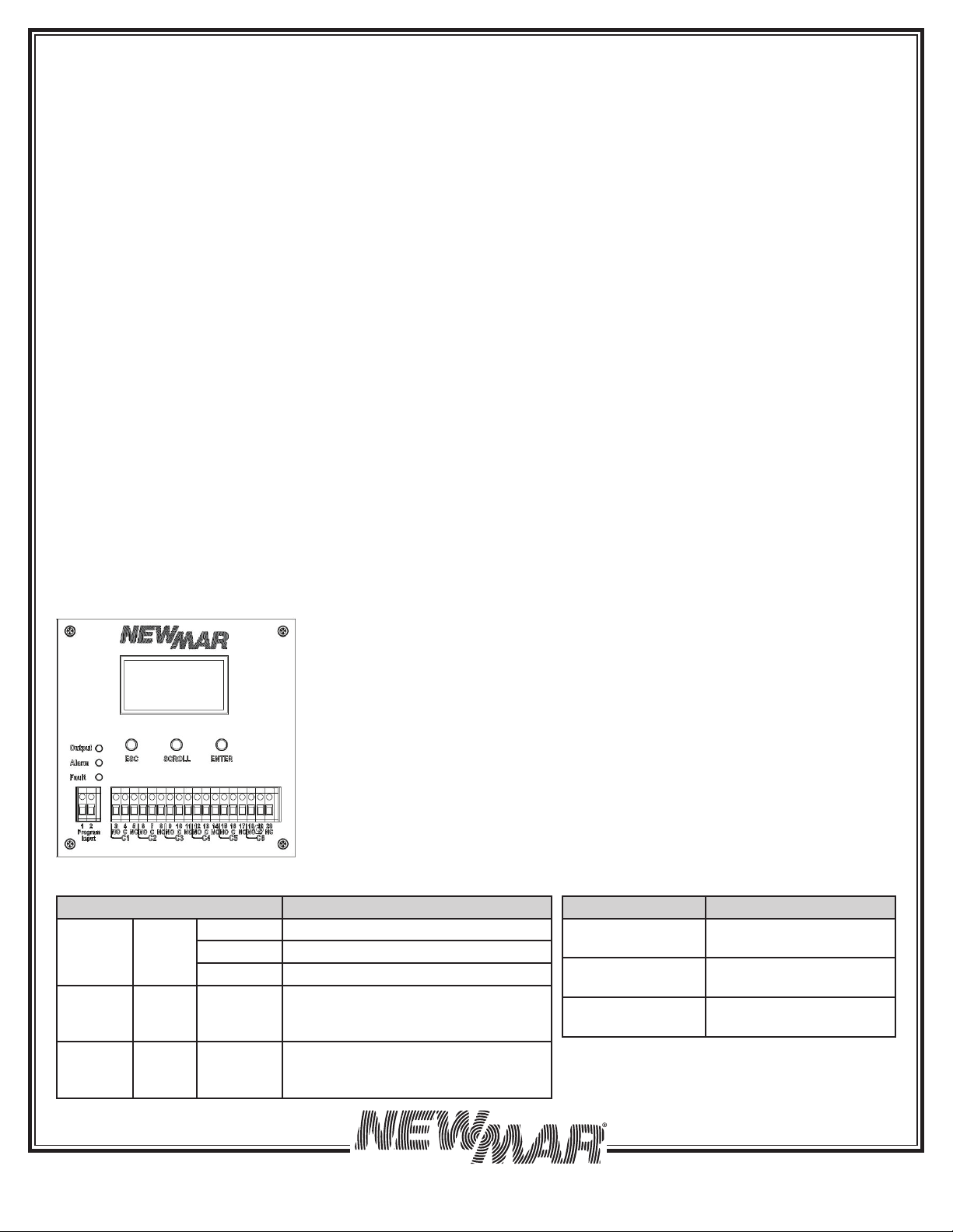
5.5 Operation the Control Panel
The control panel includes four-line LCD display, three LED indicators, three function keys, input contacts and six sets of
dry contacts. The UPS can be rotated 90 degree for vertical installation.
5.5.1 LED Indicator 5.5.2 Function Keys
LED Indicator Messages
Output Green Solid On Output is available in line mode
Flashing Output is available in battery mode
Off Output is not available
Alarm Yellow Solid On Alarms occur in the system, indicat-
ing a condition not serious enough to
stop it from providing output power.
Fault Red Solid On Faults occur in the system, indicating
a condition where backup power is
not available.
Figure 8: Control Panel
Function Key Description
ESC Back to previous menu/
page
SCROLL Jump to next page or
next selection
ENTER Enter submenu or confirm
selection


 Plus Startup manual")


