Newton Waterproofing Victron MultiPlus 12/3000/120 User manual

NEWTON
SYSTEM 500
System Sump and Pump
VICTRON MULTIPLUS
Installation Manual - 12/3000/120
Rev 2.0 - 29 April 2016
© Newton Waterproong Systems
Advanced Battery Back-Up System

2
For more information visit us online www.newtonwaterproong.co.uk
The Victron range of Inverter/Chargers provide advanced solutions to ensure that Newton Pumping Systems
continue pumping during power interruption by inverting 12V DC power from a battery (or multiple batteries) to
clean and efcient 230V power.
The MultiPlus is an extremely powerful pure sine wave inverter, a sophisticated battery charger and automatic
switch in a compact casing that features adaptive charge technology and a high-speed AC transfer switch.
WARRANTY STATEMENT
The Victron Inverter/Chargers are covered by a 2-year warranty. Warranty includes next-day on-site replacement
(delivery and collection, not decommission and installation) of the Inverter/Charger units by a temporary
replacement of the same model. If the warranty claim is upheld, this temporary unit will be exchanged with
a new unit. If the warranty claim is not upheld, the client must decide the course of action, which will include
purchase of a new replacement unit, purchase of the temporary replacement unit or return of the original unit.
Limited Product Warranties. 2-year limited product warranty from date on delivery note or invoice to the
customer.
WHAT IS COVERED BY THIS LIMITED HARDWARE WARRANTY?
This limited warranty covers replacement (Newton Waterproong Systems) only for defects in materials and
workmanship.
WHAT IS NOT COVERED BY THIS LIMITED HARDWARE WARRANTY?
• Products the supplier has not received payment for
• Normal wear & tear
• Failure to follow product installation instructions and user instructions
• Usage that is not in accordance with the product instructions
• Servicing not authorised by the manufacturer
• Problems caused by connecting devices not supplied or authorised by the manufacturer
WARRANTY INFORMATION
This warranty gives you specic legal rights, and you may also have other rights which may vary from area to
area (or jurisdiction to jurisdiction). The manufacturer’s responsibility for malfunctions and defects in the product
is limited to repair and replacement as set forth in this warranty statement. All expressed and implied warranties
for the product, including but not limited to any implied warranties and conditions of merchantability and
tness for a particular purpose, are limited in time to the term of the limited warranty which is the 2-year period
reected on your delivery note or invoice. No warranties, whether expressed or implied, will apply after the
limited warranty period has expired.
We do not accept liability beyond the remedies provided for in this limited product warranty or for
consequential or incidental damages, including without limitation, any liability for third-party claims against you,
for damages for products not being available for use. Our liability will be no more than the amount you paid for
the product that is the subject of a claim. This is the maximum amount for which we are responsible. Newton
Waterproong Systems reserve the right to change the product specication at any time.
INTRODUCTION
CONTENTS

Call us for more information on +44 (0)1732 360095
3
INTRODUCTION
CONTENTS
PAGE
INFORMATION 4
DIMENSIONS 4
SAFETY INSTRUCTIONS 4
INVERTER SIZING 5
TYPICAL DETAILS 5
INSTALLATION 6
QUICK INSTALL GUIDE 9
OPTIONAL CONNECTIONS 10
CONFIGURATION 10
BATTERY SELECTION 10
OPERATION 11
MAINTENANCE 11
TECHNICAL DATA 12
TROUBLESHOOTING 12

4
For more information visit us online www.newtonwaterproong.co.uk
This Installation Manual is written by Newton Waterproong Systems specically for the use of the Victron
Inverter/Charger units used with Newton Pumping Systems to ensure continued pumping during power
outages. The original Victron installation manual may be used for reference but contains no specic information
on the use of the unit as a Newton Battery Back-Up System and does mention uses that are not applicable to the
Newton System and so may be confusing when read in isloation.
DIMENSIONS
362mm high x 258mm wide x 218mm deep.
Weight - 18kg.
SAFETY INSTRUCTIONS
GENERAL
Please familiarise yourself with the safety features and instructions by rst reading this document before using
the equipment. This product has been designed and tested in accordance with international standards. The
equipment must be used exclusively for the purpose for which it was designed.
WARNING: ELECTRIC SHOCK HAZARD
The product is used in conjunction with wall mains, a permanent energy source (battery). Input and/or output
terminals may still be dangerously energized, even when the equipment is switched off. ALWAYS SWITCH OFF
THE AC IN SUPPLY AND DISCONNECT FROM MAINS AND BATTERY WHEN INSTALLING, MAINTAINING OR
SERVICING THIS SYSTEM. The product has no internal user-serviceable components. Do not remove the front
plate or operate the product if any panels have been removed. All servicing must be undertaken by qualied
personnel.
Never use the product where there is a risk of gas or dust explosions. Consult the battery manufacturer’s
information to ascertain that the product is intended for use in conjunction with the battery. Always comply with
the battery manufacturer’s safety instructions.
WARNING: DO NOT LIFT HEAVY LOADS WITHOUT ASSISTANCE
INSTALLATION
Read these installation instructions in full before installing the equipment. This is a Safety Class I product
(supplied with a protective grounding terminal for safety purposes). Uninterrupted protective grounding must
be provided at the AC input and/or output terminals. Alternatively the grounding point located externally on the
product may be used. Whenever it is likely that the grounding protection has been damaged, the product must
be turned off and secured against unintended operation; please contact qualied service staff.
Ensure that the connection cables are fused and tted with circuit breakers. Never replace a safety component
with a different type.
Before applying power, ensure that the available power source matches the conguration settings of the
product. This manual is to be used with the Victron MultiPlus 12/3000/120. 12/xxxx/xxx denotes the charging
volts - use with 12V batteries only. xx/3000/xx denotes the AC output capacity in VA. xx/xxxx/120 denotes the
charging current in Ah.
Ensure that the equipment is used under the correct ambient conditions (refer to data sheet for unit temperature
operating parameters). Never operate the product in a wet or dusty environment. Ensure there is adequate free
space for ventilation around the product and check that the ventilation vents are not blocked.
TRANSPORT AND STORAGE
Ensure that the mains power and battery leads have been disconnected before storing or transporting the
product.
No liability can be accepted for any transport damage if the equipment is shipped in non-original packaging.
Store the product in a dry environment; the storage temperature must be between -20°C and 60°C.
Consult the battery manufacturer’s manual in respect of transport, storage, charging, recharging and disposal of
the battery(s) and ancillary products.
INFORMATION, DIMENSIONS AND SAFETY INSTRUCTIONS
INVERTER SIZING AND TYPICAL DETAILS

Call us for more information on +44 (0)1732 360095
5
This Installation Manual is for the Victron MultiPlus Inverter/Charger unit 12/3000/120. The maximum pump size
that can be connected to these units is 750W:
• Newton CP750
• Newton NP750
• Newton SP750 Cutter
Pumps of 150, 250 & 400W can also be used with this unit but smaller MultiPlus Compact Inverter/Chargers are
available for less powerful pumps. For conrmation of the correct size of Inverter for the Newton pump being
used please refer to the Victron Inverters Data Sheet.
TYPICAL DETAILS
Below is a typical setup as part of a Newton System 500 waterproong system which can be used as a quick
install schematic. If a control panel is not used the pumps will be automatic versions and each pump will have
just one cable coming up from the conduit. Connect pump 1 directly to the mains and pump 2 to the MultiPlus.
Example 1 - 2 x Automatic Pumps - No Pump Control Panel - No Inverter/Charger Control Panels
+
MultiPlus
12
char ger inverter
victron energy
B L U E P OW E R
A C tran sf er cap ac i t y: 1x 50 A + 1 X3 0 A Inv er t e r 23 0 V
bat ter y c harger s in ew av e inverter tr a ns fe r s w itc h
powe ras s ist par al lel
c onne ct able thr ee phas e
c onne ct able
m ains on
bulk
abs or pt ion
flo at
Inv er te r on
ov er load
low b attery
tem pe ra ture
www .v ic tr on en ergy.c om
on
o ff
c har ge only
VOLT
3000 120
VA
AMP
Batt ery
B ef ore c ha rg ing r e ad t he i ns tr uc ti ons. For i ndoor use o nl y . D i s co nn ec t
the supply before making or breaki ng theconnectionstothebattery.
WA R NI NG: Exp lo sive gases, prevent f la mes a nd s pa rl s, provide
adequate venti lation duri ng charging. Chargelead-acidorLi-lonbatteries
onl y .
-
Newton MultiPlus 12/3000/120
Newton High Water Alarm
DC Battery Temp - & Temp +
pump one
pump two
Pumps compatible with
MultiPlus 12/3000/120
CP750/NP750/SP750 Cutter
For Battery dimensions
please see drawings
prefixed Batt
AC1
input
AC1
output
The Victron MultiPlus 12/3000/120
battery back up system. Installed in
conjunction with Newton's System 500
pumping systems.
The Victron system provides an
Inverter/Charger function ensuring
water can still be removed in the event
of a power outage.
Additional batteries can be added of
varying sizes and power to provide
longer protection.
For Newton system 500 pumping
Specification's please contact
Newton's technical team on
01732 360095 or enquire about using a
Newton specialist contractor.
In addition upgrades can be made to
offer extra peace of mind and further
reduce risk.
Newton Dialler - requires a BT
Telephone line.
Victron Battery monitor
Victron blue power panel
Newton System 500
Titan-Pro White Automatic pumping
System used with Newton System
500 waterproofing.
Section
To access the details mentioned above,
relevant NBS Clauses, product data and
MSDS sheets, please use this hyperlink:
Drawing Support
Checked byDesigned byDate
Scale
Notes
Ref
Drawn by
Original Ref
NOTE: This is a waterproofing detail. For the design of the structure, please use a professional designer. We strongly recommend that Newton waterproofing systems are installed by our NSBC registered contractors who will guarantee,
insure and accept liability for both the design and the installation of our systems Please refer to product data sheets before installation of our products. John Newton reserves the right to update drawings.
NEWTON
Waterproofing Systems
17 - 19 Sovereign Way, Tonbridge, TN9 1RH
Tel: 01732 360095 Fax: 01732 359033
www.newton-membranes.co.uk - sales@newton-membranes.co.uk
(EST. 1848)
Not to scale
29/04/2014
V3 - 03
AJB XXX
AJB
INFORMATION, DIMENSIONS AND SAFETY INSTRUCTIONS
INVERTER SIZING AND TYPICAL DETAILS

6
For more information visit us online www.newtonwaterproong.co.uk
Example 2 - 2 x Manual Pumps - Pump Control Panel - No Inverter/Charger Control Panels
INSTALLATION
The Inverter/Charger units are mains powered and should be installed by persons who are electrically competent
by way of appropriate training to either t a fused plug or wire directly to a fused spur. Knowledge of DC input
by battery and the connection of DC batteries leads to both the battery(s) and the Inverter/Charger is required.
The product must be installed in a dry and well-ventilated area, as close as possible to the batteries. There
should be a clear space of at least 100mm around the appliance for cooling.
Excessively high ambient temperature will result in the following:
• Reduced service life
• Reduced charging current
• Reduced peak capacity, or shutdown of the inverter
The unit must be installed in a vertical position. Never mount the appliance directly above the batteries.
JO H N NEW TON
& C O M P A N Y L I M I T E D (EST. 1848)
CONTROL PANEL - PRO 2
WA R N ING
SHOCK HAZARD ISOLATE BO TH POWERSUPPLIES,
GRID MAINS AND BAT TERY BACK-UPPOWERSUPPLY
B EF O R E OPENING
YOU R COMPANY NAME&
LO G O O N P LA TE F ITTED
TO T HIS R ECESS
PU MP1 R E S ET
& MUTE
PU MP2 R E S ET
& MUTE
PU MP 1 PU MP 2
Dialer is mounted within
the control panel with
purchase code CP7
Newton Control Panel
MultiPlus 12/3000/120
pump one
pump two
Main Float
Alarm Float
+
MultiPlus
12
char ger inverter
victron energy
B L U E P OW E R
A C tran sf er cap ac i t y: 1x 50 A + 1X3 0 A Inv er te r 230V
bat ter y char ger s inew av e inv erter tr a ns fe r s w itch
powe ras s ist p ar al lel
c onne ct able thr ee phase
c onne ct able
m ains on
bulk
abs or pt ion
flo at
Inv er te r on
ov er load
low b attery
tem pe ra ture
www .v ic tr on en ergy.c om
on
o ff
c har ge only
VOLT
3000 120
VA
AMP
Batt ery
B ef ore c ha rg i ng re ad the i ns tr uc ti ons. For i ndoor u se onl y. D i s co nn ect
the supply before making or breaki ng theconnectionstothebattery.
WAR NI NG: Expl osive gases, prevent fl a mes and s pa rl s , provide
adequate venti lation duri ng charging. Chargelead-acidorLi-lonbatteries
onl y .
-
Pumps compatible with
MultiPlus 12/3000/120
CP750/NP750/SP750 Cutter
For Battery dimensions
please see drawings
prefixed Batt
DC Battery
Temp - & Temp +
AC1
input
Grid input
connect to
AC1
output
The Victron MultiPlus 12/3000/120
battery back up system. Installed in
conjunction with Newton's System 500
pumping systems.
The Victron system provides an
Inverter/Charger function ensuring
water can still be removed in the event
of a power outage.
Additional batteries can be added of
varying sizes and power to provide
longer protection.
For Newton system 500 pumping
Specification's please contact
Newton's technical team on
01732 360095 or enquire about using a
Newton specialist contractor.
In addition upgrades can be made to
offer extra peace of mind and further
reduce risk.
Newton Dialler - requires a BT
Telephone line.
Victron Battery monitor
Victron blue power panel
Newton System 500
Titan-Pro White Manual pumping
System used with Newton System
500 waterproofing.
Section
To access the details mentioned above,
relevant NBS Clauses, product data and
MSDS sheets, please use this hyperlink:
Drawing Support
Checked byDesigned byDate
Scale
Notes
Ref
Drawn by
Original Ref
NOTE: This is a waterproofing detail. For the design of the structure, please use a professional designer. We strongly recommend that Newton waterproofing systems are installed by our NSBC registered contractors who will guarantee,
insure and accept liability for both the design and the installation of our systems Please refer to product data sheets before installation of our products. John Newton reserves the right to update drawings.
NEWTON
Waterproofing Systems
17 - 19 Sovereign Way, Tonbridge, TN9 1RH
Tel: 01732 360095 Fax: 01732 359033
www.newton-membranes.co.uk - sales@newton-membranes.co.uk
(EST. 1848)
Not to scale
29/04/2014
V3 - 02
AJB XXX
AJB
INSTALLATION
INSTALLATION

Call us for more information on +44 (0)1732 360095
7
Example 3 - 2 x Automatic Pumps - 1 x Pump Control Panels - 1 x Inverter/Charger Control Panels - 1 x Battery
Monitor Module
POSITIONING
NOTE: ALL POWER INVETERS NEED TO BE INSTALLED INTERNALLY IN A DRY AND WELL VENTILATED SPACE
• The product is suitable for wall mounting
• Do not place the battery directly below the Victron MultiPlus
• The appliance can be mounted horizontally as well as vertically; vertical mounting is preferable. The vertical
position offers optimum cooling
• Please note: All aspects of the installation must be done without AC being connected to mains until all
components of the system have been installed
• The interior of the product must remain accessible after installation
• Use only the DC cables supplied with the unit to minimize cable voltage losses
• For safety purposes, this product should be not be installed close to chemicals, synthetic components,
curtains or other textiles, etc
pump one
pump two
JO H N N EW TON
& COM PAN Y LI M IT ED ( ES T . 184 8)
CON TROL P ANEL - PRO2
WA R N ING
SHOCK HAZARD ISOLATE B OTH POWERSUPPLIES,
GRID MAINS AND BAT TERY BACK-UPPOWERSUPPLY
B EF O R E O PENING
Y O U R C OM P ANY NAME &
LO GO O N P L ATEFITTED
T O TH I S R EC ESS
PU MP 1 R E S ET
& MUTE
PU MP 2 R E S ET
& MUTE
PU MP 1 PU MP 2
Newton Control Panel-Pro
MultiPlus 12/3000/120
VE.Net Blue Power Panel
VBC Battery Monitor Module
DC Battery
Dialer is mounted within
the control panel with
purchase code CP7
Main Float
Alarm Float
RJ45 (UTP cable)
VE Bus
VE.NET BLUE POWERPANEL
v ic t ro n en ergy
Shunt 1/2000A 50mV
Bat -
Temp - & Temp +
RJ45
Shunt -
Shunt +
v i c t r o n energy
V E. Ne t Ba t t er y C o nt r o ller
www .v ic tr on en ergy.c om
Bat +
+
MultiPlus
12
char ger inverter
victron energy
B L U E P OW E R
A C tran sf er cap ac i t y: 1x 50 A + 1 X 30 A Inv er t e r 230V
bat ter y c harger s in ew av e inver ter tr a ns fe r sw itch
powe ras s ist par al lel
c onne ct able thr ee p hase
c onne ct able
m ains on
bulk
abs or pt ion
flo at
Inv er te r on
ov er load
low b attery
tem pe ra ture
www .v ic tr on en ergy.c om
on
o ff
c har ge only
VOLT
3000 120
VA
AMP
Batt ery
B ef ore c ha rg i ng re ad t he i ns tr uc ti ons. For i n d oor use o nl y . Di s co nn ect
the supply before making or breaki ng theconnectionstothebattery.
WA R NI NG: E xp lo sive gases, prevent fl a mes a nd s pa rl s, provide
adequate venti lation duri ng charging. Chargelead-acidorLi-lonbatteries
onl y.
-
+
-
Pumps compatible with
MultiPlus 12/3000/120
CP750/NP750/SP750 Cutter
For Battery dimensions
please see drawings
prefixed Batt
For Battery dimensions
please see drawings
prefixed Batt
AC1
input
Grid input
connect to
AC1
output
The Victron MultiPlus 12/3000/120
battery back up system. Installed in
conjunction with Newton's System 500
pumping systems.
The Victron system provides an
Inverter/Charger function ensuring
water can still be removed in the event
of a power outage.
Additional batteries can be added of
varying sizes and power to provide
longer protection.
For Newton system 500 pumping
Specification's please contact
Newton's technical team on
01732 360095 or enquire about using a
Newton specialist contractor.
In addition upgrades can be made to
offer extra peace of mind and further
reduce risk.
Newton Dialler - requires a BT
Telephone line.
Victron Battery monitor
Victron blue power panel
Newton System 500
Titan-Pro White Manual pumping
System used with Newton System
500 waterproofing.
Section
To access the details mentioned above,
relevant NBS Clauses, product data and
MSDS sheets, please use this hyperlink:
Drawing Support
Checked byDesigned byDate
Scale
Notes
Ref
Drawn by
Original Ref
NOTE: This is a waterproofing detail. For the design of the structure, please use a professional designer. We strongly recommend that Newton waterproofing systems are installed by our NSBC registered contractors who will guarantee,
insure and accept liability for both the design and the installation of our systems Please refer to product data sheets before installation of our products. John Newton reserves the right to update drawings.
NEWTON
Waterproofing Systems
17 - 19 Sovereign Way, Tonbridge, TN9 1RH
Tel: 01732 360095 Fax: 01732 359033
www.newton-membranes.co.uk - sales@newton-membranes.co.uk
(EST. 1848)
Not to scale
29/04/2014
V3 - 01
AJB XXX
AJB
INSTALLATION
INSTALLATION

8
For more information visit us online www.newtonwaterproong.co.uk
FIXING TO THE WALL
Fix the provided blue top xing bracket to the wall via the 3 pre-drilled holes. Screws are provided. It is
important to x the bracket level. Attach the MultiPlus to the top support bracket using the lugs on the rear of
the unit. Complete the x by screwing the bottom of the MultiPlus to the wall via the bottom 2 holes using the
screws provided. Carefully mark out the hole centres then take the MultiPlus off the wall to drill the holes.
Note: Rawl plugs will be required for the screws for certain wall types (not supplied).
CONNECTION OF BATTERY CABLES
1. Use an insulated box spanner in order to avoid shorting the battery. Avoid shorting the battery cables
2. Connect the battery cables: the + (red) and the - (black), to the battery. Reverse polarity connection (+ to –
and – to +) will cause damage to the product and will void the warranty
3. Secure the nuts tightly in order to reduce the contact resistance as much as possible
INSTALLATION
INSTALLATION AND QUICK INSTALL GUIDE

Call us for more information on +44 (0)1732 360095
9
CONNECTION OF THE AC CABLING
This is a Safety Class I product (supplied with a protective grounding terminal). Uninterrupted protective
grounding must be provided at the AC input and/or output terminals and/or chassis grounding point located
externally on the product.
The MultiPlus is provided with a ground relay that automatically connects the Neutral output to the chassis if
no external AC supply is available. If an external AC supply is provided, the ground relay H will open before the
input safety relay closes. This ensures the correct operation of an earth leakage circuit breaker that is connected
to the output. An uninterrupted grounding can also be secured by means of the grounding wire of the AC input.
Otherwise the casing must be grounded.
The mains -input & output terminal connector can be found on the bottom of the MultiPlus. The mains cable
must be connected to the connector with a three-wire cable via the terminal blocks found on the printed circuit
board. Use a three-wire cable with a exible core and a cross section of 2.5mm².
PROCEDURE
Proceed as follows to connect the AC cables:
• The AC input cable (from mains) can be connected to the terminal block “AC–in”. From left to right: “PE”
(earth), “N” (neutral) and “L” (phase). The AC input must be protected by a fuse or magnetic circuit breaker
rated at 16A or less, and cable cross-section must be sized accordingly. If the input AC supply is rated at a
lower value, the fuse or magnetic circuit breaker should be down sized accordingly
• The AC output cable (to control panel or pump 1) can be connected directly to the terminal block “AC-
out-1”. From left to right: “PE” (earth), “N” (neutral) and “L” (phase). With its PowerAssist feature the Multi
can add up to 3kVA (that is 3000 / 230 = 13A) to the output during periods of peak power requirement.
Together with a maximum input current of 16A this means that the output can supply up to 16 + 13 = 29A.
An earth leakage circuit breaker and a fuse or circuit breaker rated to support the expected load must be
included in series with the output, and cable cross-section must be sized accordingly. The maximum rating
of the fuse or circuit breaker is 32A. Do not use AC output 2
QUICK INSTALL GUIDE
The steps in bold are indicated on the gure on page 8:
1. Screw the top bracket to a suitably strong substrate using the screws provided. Rawl plugs will be required
for the screws for certain wall types (not supplied)
2. Place unit onto the bracket using the lugs to the rear of the unit. Screw the bottom of the unit to the wall
3. Unscrew and remove the front panel. Note: All cables will pass up though the bottom of the unit prior to
connections being made
4. Wire AC IN with correctly rated mains cable. Add 3-pin mains plug or wire to a switched fused spare,
both of which should be tted with a 13amp fuse. Do not plug in or turn on at the spur at this stage
5. Wire AC OUT with correctly rated mains cable from either a Newton automatic pump, or from the ‘pump
2’ connection of the CP2 or CP9 control panel
6. Wire the temperature sensor cable into the T-SENSE terminal
7. Connect the black battery cable to the left Negative terminal
8. Connect the red battery cable to the right Positive terminal
9. Connect the black battery cable and the temperature sensor cable to the negative terminal on the battery
10. Connect the red battery cable to the positive terminal on the battery
11. The system will start running off the batteries
12. Plug the AC IN into mains power or switch on the fused spur
INSTALLATION
INSTALLATION AND QUICK INSTALL GUIDE

10
For more information visit us online www.newtonwaterproong.co.uk
A number of optional connections are possible. Undo the four screws at the front of the enclosure and remove
the front panel.
NOTE: ALL 230v & 12V POWER must be fully isolated and turned off prior to removing the cover of this unit.
ONLY TECHNICALLY COMPETENT AND TRAINED technicians should alter and install any additional products
features to the unit.
TEMPERATURE SENSOR
The temperature sensor supplied with the product may be used for temperature-compensated charging. The
sensor is insulated and must be mounted on the batteries negative terminal. Default output voltages for Float
and Absorption are at 25°C. In adjust mode temperature compensation is disabled.
VICTRON BMV600S BATTERY MONITOR
The BMV600S provides real time information for the battery or bank of multiple batteries:
• Battery voltage
• Discharge current
• Capacity as a %
Please refer to product installation manual.
VICTRON BLUE POWER PANEL
The Blue Power Panel provides control and monitoring of the Victron Inverter/Charger. Features include on/off
control of MultiPlus Inverter/Charger units and graphic illustration of system charge/discharge, capacity in %
real time and time to go until discharged. Please refer to product installation manual.
VICTRON COLOR CONTROL PANEL
The Color Control Panel adds a number of extra features over the Blue Power Panel such as Ethernet or Sim
Card internet capability with remote monitoring via web portal and data storage on SD card. Please refer to
product installation manual.
CONFIGURATION
• Settings should be carried out by a competent person.
• Carefully read the instructions before changes are made.
• Batteries should be placed in a dry and well-ventilated area during charging and not directly below the
MultiPlus.
• Standard settings: ready for use
On delivery, the MultiPlus is set to standard factory values ready for use as part of a Newton Pumping System
with charging voltages set for the three batteries supplied by Newton Waterproong Systems for use within
power supplies of 230V input voltage and 50Hz frequency. Inverter output voltage is set to 230V AC. There is no
need to change any of the default settings for use within the UK.
BATTERY SELECTION
The following batteries have been selected to be used with the MultiPlus Inverter/Charger units:
• NorthStar 60FT - 60Ah, 99.9% lead, extra long life battery - 12V - Purchase code BB20
• NorthStar 100FT - 100Ah, 99.9% lead, extra long life battery - 12V - Purchase code BB21
• NorthStar 190FT - 190Ah, 99.9% lead, extra long life battery - 12V - Purchase code BB22
Multiple batteries can be used in parallel to increase the charge of the 12V supply to the inverter. Please refer to
the data sheet for further information. The maximum sized battery bank that can be used with each MultiPlus
12/3000/120 is 1200Ah
OPTIONAL CONNECTIONS, CONFIGURATION, AND BATTERY SELECTION
OPERATION AND MAINTENANCE
Call us for more information on +44 (0)1732 360095
11
OPERATION
On/Off/Charger Only Switch
For all operation as a battery back-up system the switch should be in the 'on' position, meaning the product is
fully functional, powering the pumps with through power during times of normal power supply, and inverter
power during a power outage. When mains power is not interrupted, the unit will charge the batteries also.
• Charge states (see LED Indications on page 7 also)
• Bulk - Heavy and fast charge for batteries that are very or fully depleted
• Absorption - Final top up charge at a lower charge rate than Bulk
• Float - Trickle charge for when batteries are fully charged to replace charge that is lost over time. This
ensures that the batteries are always fully charged
• If the voltage at the “AC-in” terminal is not within specications, during a power outage, for example, the
inverter will switch on, continuing power to the pumping system until the battery(s) is depleted
• There is no need to switch the unit to “charger only” mode
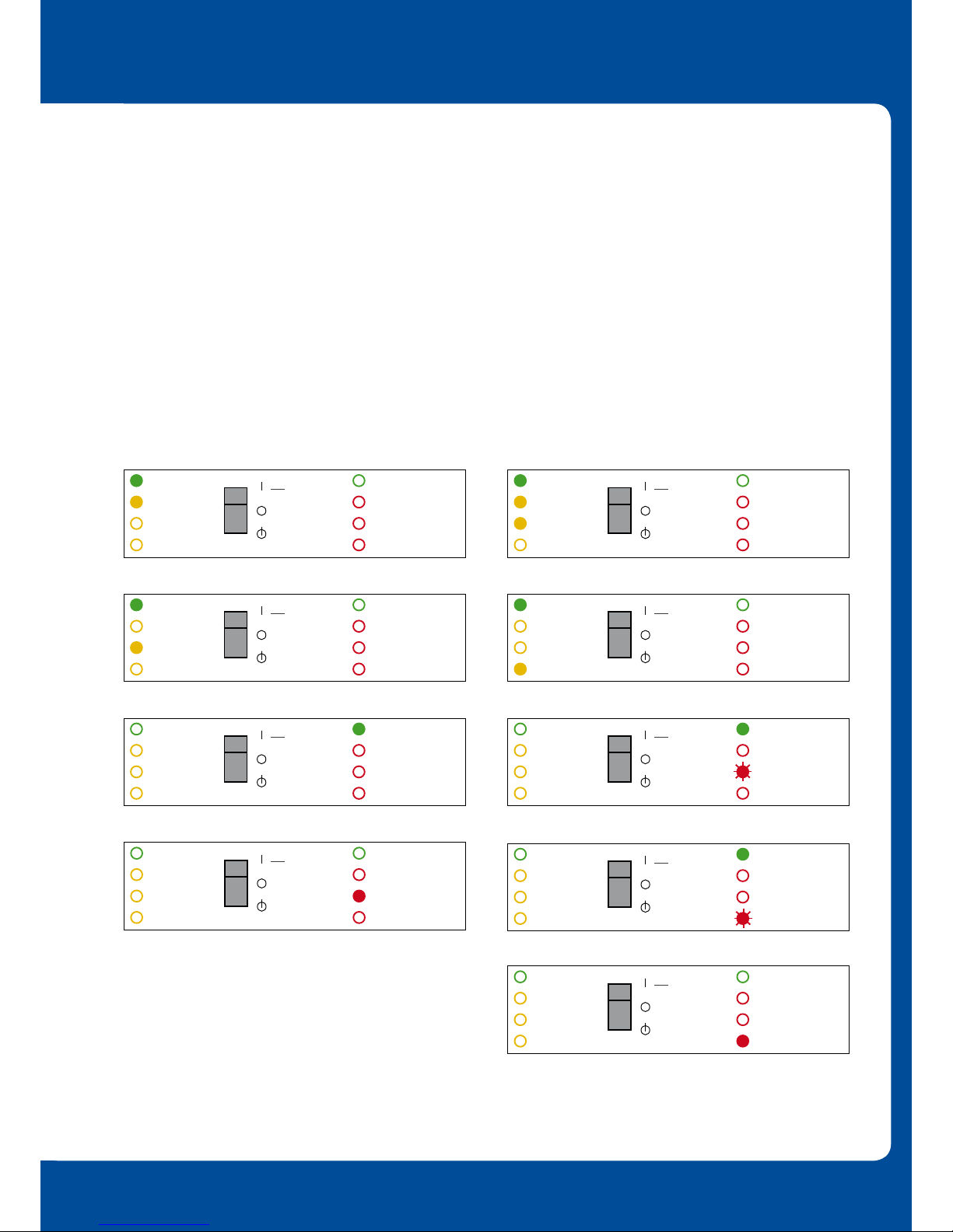
LED Indications - Standard operating parameters of inverter and charger
Charger Inverter Charger Inverter
MAINTENANCE
The unit does not require specic maintenance. All
connections should be checked once a year as part of
the pump servicing regime. Avoid moisture and oil/soot/
vapours, and keep the device clean.
Pumps are powered by the mains through the MultiPlus. Charger is
operating in Bulk (heavy charge) mode. Pumps are powered by the mains through the MultiPlus. Charger is
about to change from Bulk to Absorption (top up charge) mode.
Power is interrupted. Pumps are powered by the batteries through
the inverter.
mains on
bulk
apsorbtion
oat
on
off
charger only
inverter on
overload
low battery
temperature
mains on
bulk
apsorbtion
oat
on
off
charger only
inverter on
overload
low battery
temperature
mains on
bulk
apsorbtion
oat
on
off
charger only
inverter on
overload
low battery
temperature
Pumps are powered by the mains through the MultiPlus. Charger
is in Absorption (top up charge) mode.
mains on
bulk
apsorbtion
oat
on
off
charger only
inverter on
overload
low battery
temperature
Pumps are powered by the mains through the MultiPlus. Charger
is in Float (trickle charge) mode.
mains on
bulk
apsorbtion
oat
on
off
charger only
inverter on
overload
low battery
temperature
mains on
bulk
apsorbtion
oat
on
off
charger only
inverter on
overload
low battery
temperature
Power is interrupted. Pumps are powered by the batteries through
the inverter. The battery is almost fully exhausted.
mains on
bulk
apsorbtion
oat
on
off
charger only
inverter on
overload
low battery
temperature
Power is interrupted. Inverter has switched off due to low battery
voltage.
mains on
bulk
apsorbtion
oat
on
off
charger only
inverter on
overload
low battery
temperature
Power is interrupted. Inverter internal temperature is approaching
a critical level.
mains on
bulk
apsorbtion
oat
on
off
charger only
inverter on
overload
low battery
temperature
Power is interrupted. Inverter has switched off due to high internal
temperature.
OPTIONAL CONNECTIONS, CONFIGURATION, AND BATTERY SELECTION
OPERATION AND MAINTENANCE

“As part of our policy of continuous product improvement we reserve the right to change our specifications at any time”
“As part of our policy of continuous product improvement we reserve the right to change our specifications at any time”
Problem Cause Solution
Inverter operation not
initiated when switched on
The battery voltage is excessively high or
too low. No voltage on DC connection.
Ensure that the battery voltage is within
the correct range.
The charger is not
functioning.
Circuit breaker or fuse in the AC-in input
is open as a result of overload.
Remove overload or short circuit on
AC-out-1 or AC-out-2, and reset
fuse/breaker.
The battery fuse has blown. Replace the battery fuse.
The battery is not
completely charged
Poor battery connection Check the battery connections
The charger does not
operate.
“Bulk” LED flashes
and
“Mains on” LED
illuminates.
MultiPlus is in “Bulk protection” mode
thus, the maximum bulk charging time
of 10 hours is exceeded.
Such a long charging time could indicate
a system error (e.g. a battery
cell short-circuit).
Check your batteries.
NOTE: You can reset the error mode by
switching off and back on the MultiPlus.
The battery is
overcharged.
Poor battery condition. Replace the battery.
The battery temperature is too high
(due to poor ventilation, excessively high
environmental temperature).
Improve ventilation, install batteries
in a cooler environment
Newton Waterproong Systems Is A Trading Name Of
John Newton & Company Ltd.
Newton House, 17-19 Sovereign Way
Tonbridge, Kent TN9 1RH
T: +44 (0)1732 360095
E: info@newtonwaterproong.co.uk
W: www.newtonwaterproong.co.uk
TECHNICAL DATA
All technical data is available on page 2 of the Data Sheet.
TROUBLESHOOTING
The table on page 12 provides a quick reference of the more common faults. Disconnect the battery(s) and
pumping systems before diagnosing the fault. Consult Newton Waterproong Systems if the fault cannot be
resolved.
Table of contents
Popular Inverter manuals by other brands

Xantrex
Xantrex Freedom SW 815-2024 owner's guide

CARLO GAVAZZI
CARLO GAVAZZI ISMG 315 user manual

Black & Decker
Black & Decker PI100BB instruction manual

Twin Disc
Twin Disc TMC 260 Service manual

Generac Power Systems
Generac Power Systems 04673-2 Installation and owner's manual

Haier
Haier AS12TA2HRA Service manual

Black & Decker
Black & Decker PI100SB instruction manual

EcoEnergy
EcoEnergy SW-2000 12V Synchronous user manual

Siemens
Siemens SINAMICS G120P operating instructions

Sunforce
Sunforce 5000 Watt POWER INVERTER user manual

Clarke
Clarke IG1000 Operation & maintenance instructions

Flin Energy
Flin Energy FlinSlim MPPT user manual


