Sunbeam Nova Universal User manual

supporting sustainability
Universal
Symmetrical
Symmetrical Portrait
December 2022 | Version 2.0 | This is the English translation of the original Dutch installation manual
Sunbeam Nova
Installation manual
EN
General
Description of the user
This document is intended for the installer. Sunbeam Nova should only be installed by a trained installer who has fully read and understood the contents of this
manual.
Intended use and reasonably foreseeable misuse
Sunbeam Nova is a mounting system for installing solar panels on flat roofs. Sunbeam Nova should only be used according to the instructions in this document.
Sunbeam Nova must only be used with the original accessories and components supplied by the supplier. Any other use is considered improper use and may lead
to injury, damage to the system and void the warranty.
Symbols used
Symbol Meaning
WARNING
This symbol indicates a hazardous situation which, if not avoided, could result in serious injury or death.
NOTICE
This symbol indicates situations not related to personal injury.
COMMENT
This symbol indicates useful additional information.
Safety equipment
Always wear personal safety equipment and fall protection while installing Sunbeam Nova.
Safety instructions
Read and understand the instructions below before installing Sunbeam Nova.
WARNING
• Always follow the national safety regulations in the country of installation.
• Always use the configuration and ballast plan derived from the Sunbeam
Calculator software during installation.
• Always employ suitable safety measures on the roof such as fall
protection.
• Make sure the roof is free of obstructions and clean before installation.
• Check that the roof covering is in good condition and that the roof
structure is strong enough to support the complete solar energy system
as an extra load, in addition to the loads caused by wind, water and snow.
• Check that the roof covering can withstand the maximum point load of the
feet of the Sunbeam system. If necessary, the point load can be reduced
by using additional feet.
• If in doubt about any of the above, consult a structural engineer and/or
roofing contractor.
• Always keep a copy of the configuration and ballast plan and this manual
with the project documentation.
NOTICE
• Check that the delivery is complete before installation.
• Never place heavy pallets directly on a roof, the localised load can be very
high.
• Be careful with packages that can blow away and with sharp parts that
can damage the roof covering.
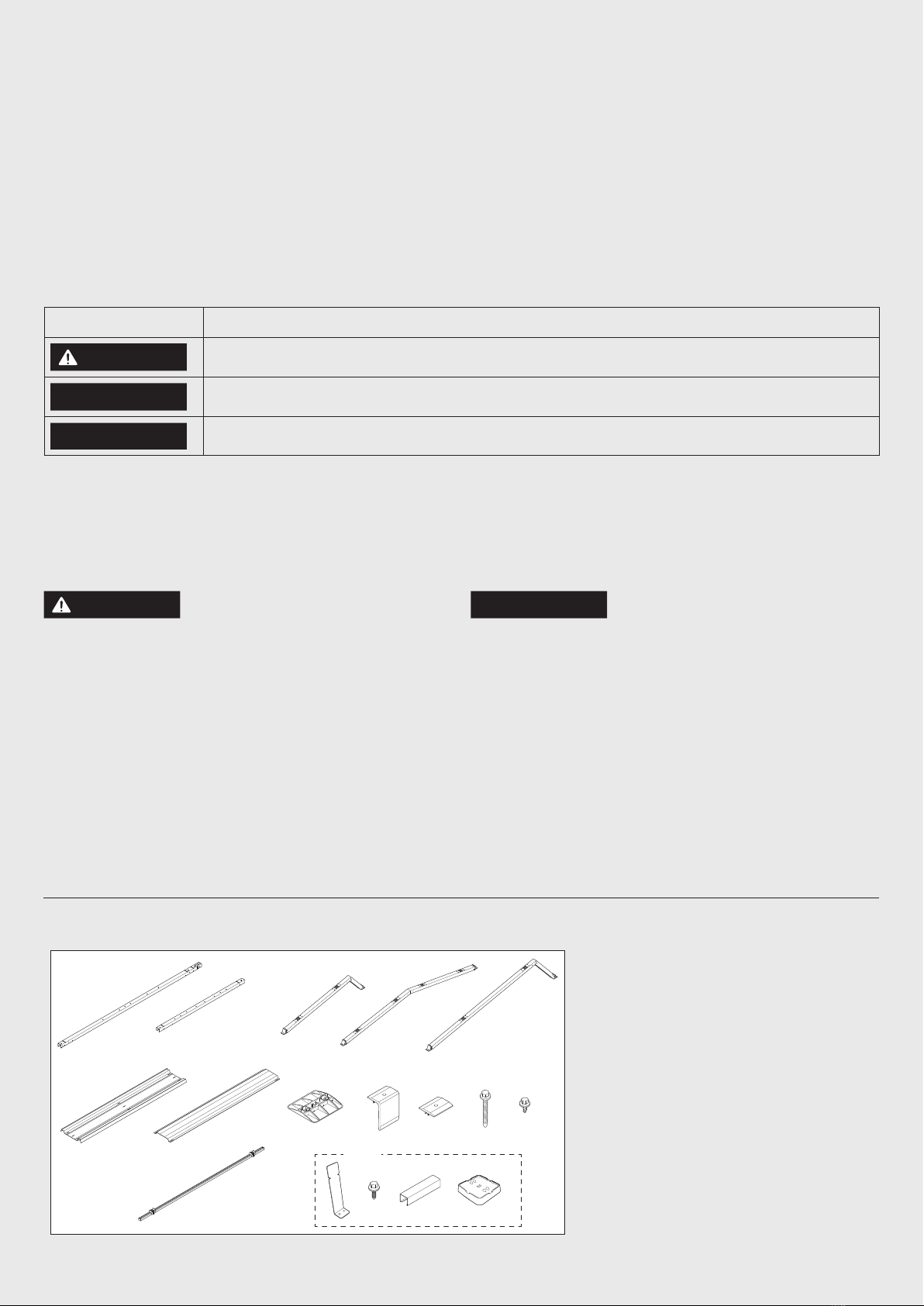
Components
BA DC E
F G H I
N O P Q
J
M
K L
A. Base unit
B. Base unit end Universal
C. Carrier Universal
D. Carrier Symmetrical
E. Carrier Symmetrical Portrait
F. Ballast rack
G. Wind plate
H. Foot
I. End clamp
J. Mid clamp
K. Clamp screw
L. Short screw
M. Sizing tool
N. Carrier reinforcement
O. Self-drilling screw
P. Ballast support
Q. Booster foot
Optional

Preparation
Recommended tools
Preparing a configuration and ballast plan
WARNING
• Always use the Sunbeam Calculator software with every Sunbeam project, to generate a project-specific configuration and ballast plan.
• Always check that the actual weight of the tiles used matches what is shown in the configuration and ballast plan.
• Only systems installed according to a configuration and ballast plan from the current Sunbeam Calculator at the time of ordering are eligible for the Sunbeam
product warranty.
Prepare the configuration and ballast plan.
COMMENT
The configuration and ballast plan contains all the information regarding the installation of ballast in the form of tiles. Calculate the
position and quantity of ballast for your specific project using the calculator software.
Marking the field
Mark two sides of the field with chalk or string on the roof. Follow the configuration plan.
COMMENT
• Maintain the spacing to the roof edge as described in the configuration plan.
• Make sure the field is straight and perpendicular. Do this using a folding square or a laser.
TIP: If you don't have a folding square or laser, you can also draw a triangle that automatically becomes
perpendicular, by drawing out 2 straight sides of 3 and 4 metres and connecting them to a sloping side of 5
metres.
Socket bit 3/8 inchElectric screwdriver Phillips screwdriver Chalk line reel + chalk
3/8
Setting up sizing tools
COMMENT
For large installations, it is recommended to use several sizing tools.
1. To adjust the sliding block, loosen the screw a few turns.
2. Place the sizing tool over the long side of a solar panel.
COMMENT
For Symmetrical Portrait, adjust the sizing tool on the short side
of the panel.
3. Slide the sliding blocks against the side of the solar panel and
screw in place.
COMMENT
The sizing tool can also be set with a tape measure.

Universal
installation
Installing the mounting profiles
1. Press one foot under each base unit, on the side with the
connector.
COMMENT
The feet snap into place at the holes in the
side of the base unit.
2. Also press a foot under each universal base unit end.
Click!
3. Lay the base units on the roof according to the configuration plan
and slide them together as far as they will go.
4. Press a foot under the beginning of each row of base units.
Placing the ballast racks and ballast
5. Place the sliding blocks of a set sizing tool on two base units lying
side by side.
COMMENT
Make sure the outer row of base units
remain in their marked position.
6. Repeat the previous step until all the base units are in place.
COMMENT
Once the first three rows of base units are
positioned, the first ballast racks can already be placed.
A
B
A
B
B
7. Place a ballast rack crosswise on two rows of base units. Align the
holes in the base unit with the slots in the ballast racks and fasten
with one short screw per side. Tighten the screws with 3 to 4 Nm.
COMMENT
Lay the ballast racks located at the outer
edge of the field as far as possible towards the field edge. An extra
hole is provided in the base unit at position B for this purpose.
8. Follow the ballast plan to lay all the ballast racks.
COMMENT
When using double ballast racks, place one
ballast rack in position A and one in position B.
1
2
3
9. Optional: Press the ballast support onto a foot, slide it under the
centre of a ballast rack and secure with a short screw.
COMMENT
Follow the configuration and ballast plan to
lay all the ballast supports.
10. Place the ballast on the ballast racks.
3-4 Nm
COMMENT
• Place the ballast as described in the ballast plan.
• Only use the type of ballast as described in the ballast plan
• Always lay the ballast as far as possible towards the base units.
• Never stack ballast.
11. Lay out any return cables required.
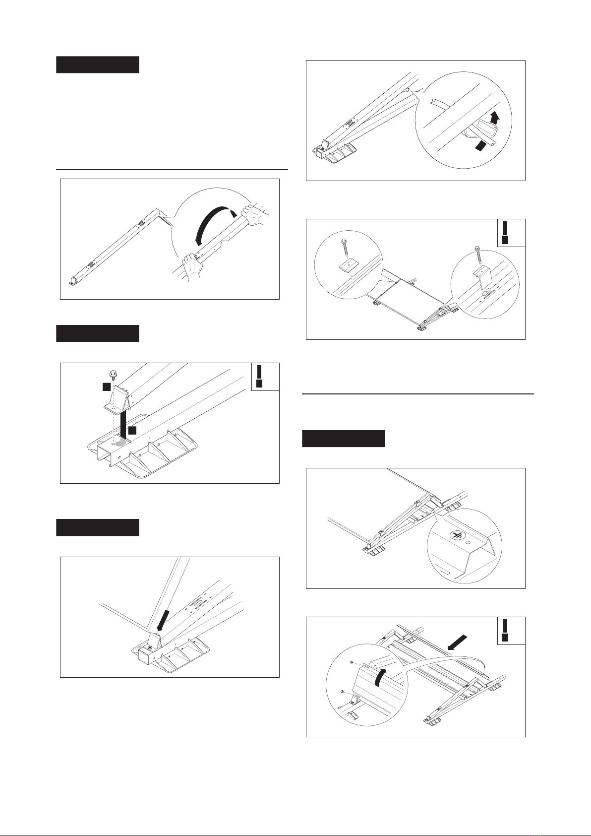
Placing the carriers and panels
12. Bend the universal carrier with two hands over the knee point and
place it directly on the base unit.
COMMENT
Never bend the knee in the wrong
direction.
1
2
13. Push both yellow end blocks of the universal carrier into the
slots of one of the base units and fasten with two short screws.
Tighten the screws with 5 to 7 Nm.
COMMENT
Make sure the holes of the end block and
the base unit are directly aligned above each other.
14. Place a solar panel against the yellow end blocks of the universal
carrier and keep it upright.
5-7 Nm
15. Connect the solar panel to the adjacent solar panel and attach
the cables in the cable clips located at the bottom of the universal
carrier.
16. Lay the panel down on the universal carrier. Tighten the screws
with 5 to 9 Nm.
Finishing
17. Attach the end clamps and mid clamps with clamp screws to the
universal carriers to clamp the solar panels. Tighten the screws
with 5 to 9 Nm.
COMMENT
There is a gap of about 10mm between
two panels.
18. If required, level the fields by using the 6mm hole in the ballast
rack.
19. Place a wind plate on the back of the carriers and secure with two
short screws per side. Tighten the screws with 3 to 4 Nm.
5-9 Nm
3-4 Nm

Symmetrical
installation
Placing the feet and base units
1. Press one foot under each base unit, on the side with the
connector.
COMMENT
The feet snap into place at the holes in the
side of the base unit.
Click!
2. Lay the base units on the roof according to the configuration plan
and slide them together as far as they will go.
3. Press a foot under the beginning of each row of base units.
4. Press a foot under the centre of the base unit where a ballast rack
will lie.
COMMENT
Follow the ballast plan.
Placing the ballast racks and ballast
5. Place the sliding blocks of a set sizing tool on two base units lying
side by side.
COMMENT
Make sure the outer row of base units
remain in their marked position.
6. Repeat the previous step until all the base units are in place.
COMMENT
Once the first three rows of base units are
positioned, the first ballast racks can already be placed.
A
B
A
B
B
7. Place a ballast rack crosswise on two rows of base units. Align the
holes in the base unit with the slots in the ballast racks and fasten
with one short screw per side. Tighten the screws with 3 to 4 Nm.
COMMENT
Lay the ballast racks located at the outer
edge of the field as far as possible towards the field edge. An extra
hole is provided in the base unit at position B for this purpose.
8. Follow the ballast plan to lay all the ballast racks.
COMMENT
When using double ballast racks, place one
ballast rack in position A and one in position B.
1
2
3
9. Optional: Press the ballast support onto a foot, slide it under the
centre of a ballast rack and secure with a short screw.
COMMENT
Follow the configuration and ballast plan
to lay all the ballast supports.
10. Place the ballast on the ballast racks.
COMMENT
• Place the ballast as described in the ballast plan.
• Only use the type of ballast as described in the ballast plan
• Always lay the ballast as far as possible towards the base units.
• Never stack ballast.
11. Lay out any return cables required.
3-4 Nm
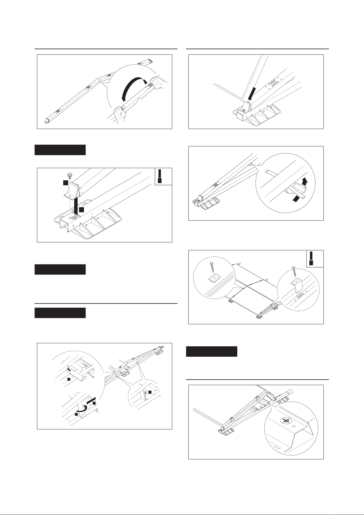
Placing carriers
12. Bend the symmetrical carrier with two hands over the knee point
and place it directly on the base unit.
COMMENT
Never bend the knee in the wrong
direction.
1
2
13. Push both yellow end blocks of the symmetrical carrier into the
slots of one of the base units and fasten with two short screws.
Tighten the screws with 5 to 7 Nm.
COMMENT
Make sure the holes of the end block and
the base unit are directly aligned above each other.
Carrier reinforcement (optional)
COMMENT
The Sunbeam calculator software
determines whether the optional carrier reinforcements are required
and included. If the carrier reinforcements are not included, proceed
to step 17.
2
4
1
3
14. Hook the carrier reinforcement into the profile of the symmetrical
carrier and rotate a quarter turn. Press through the resistance of
the profile to clamp the carrier into the profile.
15. Slide the carrier reinforcement down at an angle until the
underside rests on the base unit.
16. Fix the bottom of carrier reinforcement to the base unit with
a self-drilling screw. Place two carrier reinforcements per
symmetrical carrier.
5-7 Nm
Placing the panels
17. Place a solar panel against the yellow end blocks of the universal
carrier and keep it upright.
18. Connect the solar panel to the adjacent solar panel and attach the
cables in the cable clips located at the bottom of the symmetrical
carrier.
19. Lay the panel down on the symmetrical carrier.
20. Attach the end clamps and mid clamps with clamp screws to the
universal carriers to clamp the solar panels. Tighten the screws
with 5 to 9 Nm.
COMMENT
There is a gap of about 10mm between
two panels.
Finishing
21. If required, level the fields by using the 6mm hole in the ballast
rack.
5-9 Nm

Symmetrical Portrait
installation
Placing the feet and base units
1. Press a foot under the end of each row of base units.
COMMENT
The feet snap into place at the holes in the
side of the base unit.
Click!
2. Lay the base units on the roof according to the configuration plan
and slide them together as far as they will go.
COMMENT
Some configurations use two different
sizes of base units. Follow the instruction in the configuration plan
for the correct order.
3. Press a foot under the beginning of each row of base units.
4. Press a foot under the centre of the base unit where a ballast rack
will lie.
COMMENT
Follow the ballast plan.
Placing the ballast racks and ballast
5. Place the sliding blocks of a set sizing tool on two base units lying
side by side.
COMMENT
Make sure the outer row of base units
remain in their marked position.
6. Repeat the previous step until all the base units are in place.
COMMENT
Once the first three rows of base units are
positioned, the first ballast racks can already be placed.
A
B
A
B
B
7. Place a ballast rack crosswise on two rows of base units. Align the
holes in the base unit with the slots in the ballast racks and fasten
with one short screw per side. Tighten the screws with 3 to 4 Nm.
COMMENT
Lay the ballast racks located at the outer
edge of the field as far as possible towards the field edge. An extra
hole is provided in the base unit at position B for this purpose.
8. Place the ballast on the ballast racks.
COMMENT
• When using double ballast racks, place one ballast rack in
position A and one in position B.
• Place the ballast as described in the ballast plan.
• Only use the type of ballast as described in the ballast plan
• Always lay the ballast as far as possible towards the base units.
• Never stack ballast.
9. Lay out any return cables required.
3-4 Nm

Placing the carriers and panels
10. Bend the symmetrical portrait carrier with two hands over the
knee point and place it directly on the base unit.
COMMENT
Never bend the knee in the wrong
direction.
11. Place one bent symmetrical portrait carrier on a base unit.
COMMENT
Place every second carrier backwards.
1
2
12. Push both yellow end blocks of the symmetrical portrait carrier
into the slots of one of the base units and secure with two short
screws. Tighten the screws with 5 to 7 Nm.
COMMENT
Make sure the holes of the end block and
the base unit are directly aligned above each other.
13. Place a wind plate on the back of a symmetrical portrait carrier
and secure with two short screws per side. Tighten the screws
with 3 to 4 Nm.
COMMENT
With Symmetrical Portrait, the wind plates
are not required at every position, follow the configuration plan for
correct placement.
5-7 Nm
3-4 Nm
Placing the panels
14. Place a solar panel against the yellow end blocks of the
symmetrical portrait carrier and keep it upright.
15. Connect the solar panel to the adjacent solar panel and attach the
cables in the cable clips located at the bottom of the symmetrical
portrait carrier.
16. Lay the panel down on the symmetrical portrait carrier.
17. Attach the end clamps and mid clamps with clamp screws to the
universal carriers to clamp the solar panels. Tighten the screws
with 5 to 9 Nm.
COMMENT
There is a gap of about 10mm between
two panels.
Finishing
18. If required, level the fields by using the 6mm hole in the ballast
rack.
5-9 Nm

10 www.sunbeam.solar/en
Sunbeam BV
Kwikstaartlaan 18
NL-3704 GS Zeist
The Netherlands
+31 (0)30 - 43 00 333
December 2022 | Version 2.0
This is the English translation of the original Dutch installation manual
Sunbeam Nova
Installation manual
EN
Safety standards
The national regulations in the country of installation must be observed at all times. Make sure you are aware of the safety measures prescribed by
Sunbeam or the country of installation. If in doubt, consult your safety officer. Ensure safety or health hazards are shared with the employer, supervisor
and executive worker for their information.
General safety
• For the Netherlands: Working Conditions Decree Articles 3.16, 7.23 and 8.1 to 8.3.
• For Belgium: General Regulations for Occupational Health and Safety (ARAB).
Electrical installation
• For the Netherlands:
• NEN1010 - Chapter 7.12
• NPR 5310 - Chapter 7.12
• NEN 3140
• For Belgium: General Regulations on Electrical Installations (AREI).
Roof construction and various loads
• General:
• EN 1990
• EN 1991-1-3
• EN 1991-1-4
• For the Netherlands: NEN 7250
Sustainability
As a manufacturer and supplier of panel mounting systems, we are committed to protecting the environment. In the event of a faulty system, please
contact Sunbeam first. It may still be possible to repair the system.
Should you need to dispose the system, please dispose of the system according to the local applicable regulations. By properly disposing of the various
materials, you will help prevent potential hazards to the environment and human health. The recycling of materials also contributes to the conservation
of natural resources.
Warranty
Please refer to www.sunbeam.solar/en for warranty conditions.
This manual suits for next models
2
Table of contents
Other Sunbeam Inverter manuals

Popular Inverter manuals by other brands

Frenic
Frenic 5000VG7S Series instruction manual

Chicago Electric
Chicago Electric 92464 Assembly and operating instructions

stayer
stayer GAV2800 operating instructions

Mosa
Mosa GE 12000 KSX/GS - AVR User and maintenance guide

SOLAREVER
SOLAREVER SE1-SPT user manual

Fortress Power
Fortress Power FP-ENVY 12K Installation & user manual


