NEX ROBOTICS LPC2148 Pro User manual


LPC2148 DEVELOPMENT BOARD
NOTICE
The contents of this manual are subject to change without notice. All efforts have been
made to ensure the accuracy of contents in this manual. However, should any errors be
detected, NEX Robotics welcomes your corrections. You can send us your queries /
suggestions at
info@ne -robotics.com
Content of this manual is released under the Creative Commence cc by-nc-sa license.
For legal information refer to:
http://creativecommons.org/licenses/by-nc-sa/3.0/legalcode
•Product’s electronics is st tic sensitive. Use the product in st tic free
Environment.
•Re d the user m nu l completely before st rt using this product
Recycling:
Almost all the part of this product is recyclable. Please send this product to the recycling plant
after its operational life. By recycling we can contribute to cleaner and healthier environment
for the future generations.
NEX Robotics Pvt. Ltd. 2
www.ne -robotics.com

LPC2148 DEVELOPMENT BOARD
INDEX
1.0 INTRODUCTION..............................................................................................................................................4
1.1 Board Features....................................................................................................................................................4
1.2 LPC2148 Pro Development Board Overview....................................................................................................6
1.3 Power supply.....................................................................................................................................................7
1.4 In System Programming via UART0..................................................................................................................8
2.0 KEIL µVISION4 IDE........................................................................................................................................9
2.1 Installing Keil µVision4 IDE.............................................................................................................................9
2.2 Using Flash Magic Tool...................................................................................................................................12
2.2.1 Installing Flash Magic Tool...........................................................................................................................12
2.3 Overview of Keil µVision4 IDE.......................................................................................................................17
2.3.1 Create a Project in Keil for LPC2148 development board............................................................................18
2.3.2 CODE WALKTHROUGH............................................................................................................................29
2.3.3 Configuring Startup.s File using Configuration wizard.................................................................................34
2.4 Using uVision Debugger in simulator mode....................................................................................................37
3.1 Main E pansion Header...................................................................................................................................44
3.2 LEDs.................................................................................................................................................................45
3.3 USER SWITCHES...........................................................................................................................................45
3.4 LCD INTERFACE...........................................................................................................................................46
3.5 BUZZER..........................................................................................................................................................46
3.6 IR RECEIVER.................................................................................................................................................46
3.7 TRIMPOTS......................................................................................................................................................47
3.8 UART1/XBEE/BLUETOOTH/WIFI..............................................................................................................47
3.9 SPI INTERFACE.............................................................................................................................................47
3.10 I2C INTERFACE ..........................................................................................................................................48
3.11 ULN 2003.......................................................................................................................................................48
3.12 L293D.............................................................................................................................................................49
3.13 JTAG PORT...................................................................................................................................................50
3.14 RTC...............................................................................................................................................................50
4.0 SAMPLE PROGRAMS...................................................................................................................................51
4.1 LED CHASER..................................................................................................................................................51
4.2 IO INTERFACING..........................................................................................................................................51
4.3 BUZZER..........................................................................................................................................................52
4.4 LCD INTERFACING .....................................................................................................................................52
4.5 UART0 COMM 9600.....................................................................................................................................53
4.6 UART1 COMM 9600......................................................................................................................................53
4.7 ADC..................................................................................................................................................................54
4.8 I2C EEPROM...................................................................................................................................................54
4.9 SD MMC INTERFACE...................................................................................................................................55
4.10 DC MOTOR CONTROL...............................................................................................................................55
4.11 STEPPER MOTOR CONTROL....................................................................................................................56
4.12 RTC UART0..................................................................................................................................................56
4.13 XBEE/BLUETOOTH/WIFI WIRELESS COMMUNICATION..................................................................57
4.14 BOARD DEMO ............................................................................................................................................58
NEX Robotics Pvt. Ltd. 3
www.ne -robotics.com

LPC2148 DEVELOPMENT BOARD
1.0 INTRODUCTION
1.1 Bo rd Fe tures
LPC2148 Pro Development Board is a powerful development platform based on LPC2148
ARM7TDMI microcontroller with 512K on-chip memory. This board is powered by USB
port and does not need e ternal power supply. It is ideal for developing embedded
applications involving high speed wireless communication (Zigbee / Bluetooth / WiFi), USB
based data logging, real time data monitoring and control, interactive control panels etc. The
on-chip USB controller provides direct high speed interface to a PC/laptop with speeds up to
12Mb/s. The UART boot loader eliminates need of an additional programmer and allows you
to program using serial port. The on board peripherals include SD/MMC card interface,
USB2.0 interface, 4Kbit I2C EEPROM, Xbee wireless module interface, ULN2003 500mA
current sinking driver, L293D DC motor controller, 16X2 character LCD and many more.
The on-chip peripherals and the e ternal hardware on the development board are
interconnected using pin headers and jumpers. The I/O pins on the microcontroller can be
accessed from a 50 pin male header. The board is made from double sided PTH PCB board to
provide e tra strength to the connector joints for increased reliability.
Note:
1. Xbee / Bluetooth/ WiFi wireless module and SD/MMC card are not included with the
board and it can be bought separately from Ne Robotics website.
NEX Robotics Pvt. Ltd. 4
www.ne -robotics.com

LPC2148 DEVELOPMENT BOARD
Specific tions:
•Microcontroller: LPC2148 with
512K on chip memory
•Crystal for LPC2148: 12Mhz
•Crystal for RTC: 32.768KHz
•50 pin Berg header for e ternal
interfacing
•Wireless module adapter for
2.4GHz ZigBee (Xbee) /
Bluetooth / WiFi connectivity
•512 bytes of I2C e ternal
EEPROM
•USB Type B Connector
•SD / MMC card holder
•10pin(2X5) FRC JTAG connector
for flashing and debugging
•50 Pin E pansion header
•2 16 Character Alphanumeric
LCD
•L293D 600mA Dual DC motor
Driver
•ULN2003 500mA driver
•Dual RS232 UARTs for e ternal
communication
•Real-Time Clock with Battery
Holder
•2 Analog Potentiometers connected
to ADC
•TSOP1738 IR receiver
•4 USER Switches
•4 USER LEDs
•Reset and Boot loader switches
•3V button cell for on chip RTC
•ON/OFF switch
•Buzzer
•Schematics and Application
e amples in KEIL provided in the
documentation CD
Kit Cont ins:
1-LPC2148 Pro Development Board
1-USB Cable
1-DB9 Serial Cable
A set of 10 1-1 cables
Documentation CD contains:
I. Schematic
II. Programming Software
III. E ample Codes
LPC2148 Fe tures:
•16-bit/32-bit ARM7TDMI-S microcontroller in a tiny LQFP64 package.
•40 kB of on-chip static RAM and 512 kB of on-chip flash memory.
•In-System Programming/In-Application Programming (ISP/IAP) via on-chip boot
loader software.
•Embedded ICE RT and Embedded Trace interfaces offer real-time debugging with the
on-chip Real Monitor software and high-speed tracing of instruction e ecution.
•USB 2.0 Full-speed compliant device controller with 2 kB of endpoint RAM.
•Two 10-bit ADCs provide a total of 14 analog inputs
•Single 10-bit DAC provides variable analog output
•Two 32-bit timers/e ternal event counters (with four capture and four compare
channels each), PWM unit (si outputs) and watchdog.
•Low power Real-Time Clock (RTC) with independent power and 32 kHz clock input.
NEX Robotics Pvt. Ltd. 5
www.ne -robotics.com

LPC2148 DEVELOPMENT BOARD
•Multiple serial interfaces including two UARTs, two Fast I²C-bus (400 kbit/s), SPI
and SSP with buffering and variable data length capabilities.
•Vectored Interrupt Controller (VIC) with configurable priorities and vector addresses.
•60 MHz ma imum CPU clock available from programmable on-chip PLL with
settling time of 100 us.
•On-chip integrated oscillator operates with an e ternal crystal from 1 MHz to 25 MHz
•Power saving modes include Idle and Power-down.
•Individual enable/disable of peripheral functions as well as peripheral clock scaling
for additional power optimization.
•Processor wake-up from Power-down mode via e ternal interrupt or BOD.
•Single power supply chip with POR and BOD circuit
•CPU operating voltage range of 3.0 V to 3.6 V (3.3 V +- 10 pct) with 5 V tolerant I/O
pads.
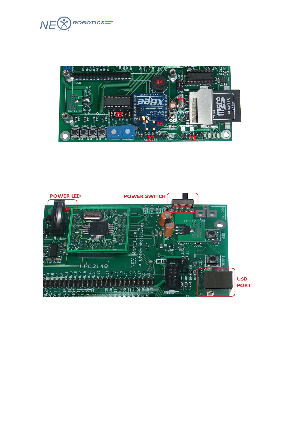
1.2 LPC2148 Pro Development Bo rd Overview
1. LPC2148 Plug-in module
2. 3V cell holder for RTC
3. UART1 DB9 connector
4. UART0 DB9 connector
5. 50-pin e pansion header
6. 2X5 JTAG header
7. ON/OFF slide switch
8. Boot loader switch
9. Microcontroller reset switch
10. USB connector B-type
11. Jumpers for LCD interface
12. Jumpers for Switches
13. Jumpers for Trim pots
14. Jumpers for Buzzer and IR
Receiver
15. Jumpers for LEDs
16. Jumpers for selection between
UART1 and Xbee
17. Jumpers for SPI – SD/MMC
interface
NEX Robotics Pvt. Ltd. 6
www.ne -robotics.com
LPC2148 DEVELOPMENT BOARD
18. Jumpers for I2C EEPROM
19. SD/MMC card socket
20. 16X2 character LCD
21. Four user switches
22. Two trim pots connected to ADC
23. Four user LEDs
24. Buzzer
25. TSOP1738 IR Receiver
26. Xbee module interface
27. ULN2003 driver side header
28. L293D o/p header
29. Jumpers for ULN2003
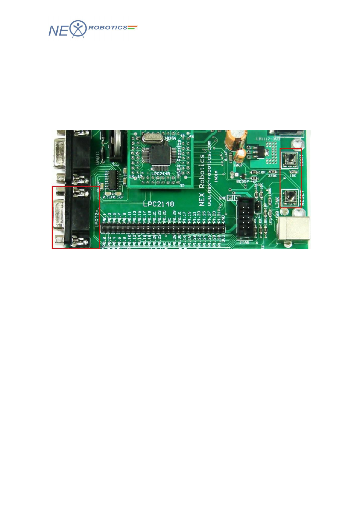
1.3 Power Supply
The USB powered version of LPC2148 development board is powered using USB port.
Slide the power switch to ON position to turn the board ON. The red LED will glow
indicating that the board is powered.
W rning: Please make sure that the USB port on your PC or any other device is capable to
source at least 400mA current.
NEX Robotics Pvt. Ltd. 7
www.ne -robotics.com
LPC2148 DEVELOPMENT BOARD
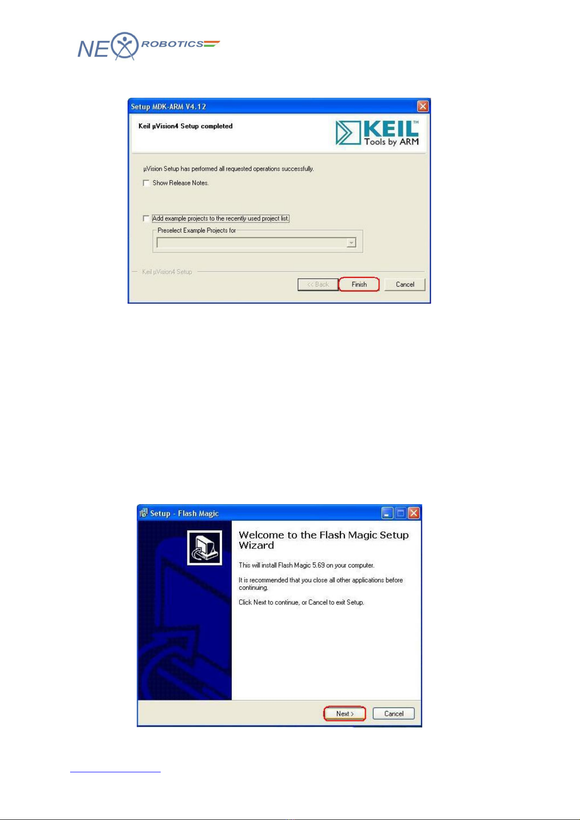
1.4 In System Progr mming vi UART0
LPC2148 microcontroller incorporates a capability to self program itself using the on-chip
UART boot loader. This eliminates the need of an e ternal programming hardware. The boot
loader code is dedicated to use UART0 on the microcontroller. Once the code is loaded on
the microcontroller UART0 is free to be used in the application. The host, in this case PC or
Laptop, requires software to transmit the he file to the microcontroller over the serial link.
For demonstration purpose we will use Flash Magic programming utility. The installation
procedure is e plained in section 2.2.1.
To enter in to the boot load mode follow the steps mentioned below:
1. Connect a DB9 cable between the selected COM port on your PC and the UART0 port on
LPC2148 development board.
2. Plug in an USB cable to the development board and slide power switch to ON position.
3. The board enters bootloader mode when BOOT switch is held down at the time of
RESET. To enter the bootloader mode, keep the BOOT switch pressed and then press and
release RESET switch. You can release the BOOT switch after reset.
NEX Robotics Pvt. Ltd. 8
www.ne -robotics.com

LPC2148 DEVELOPMENT BOARD
2.0 KEIL µVISION4 IDE
The LPC2148 microcontroller is supported by various commercially available IDEs for
compiling and debugging of the code. Keil being one of them is the widely used IDE for
LPC family of microcontrollers. The µVision4 IDE is Windows-based software
development platforms that combines a robust editor, project manager, and make facility.
µVision4 integrates all tools including the C compiler, macro assembler, linker/locator,
and HEX file generator. The evaluation version of Keil µVision4 IDE is used for
demonstrating the sample codes that are included in the CD.
The open source community has been doing a lot in the development of open source
tools for ARM architecture based microcontrollers. The open source tools are available at
zero cost and are being improved with time. Eclipse being one of them and is most
commonly used IDE due to its unique features like auto complete, project tree, etc. It
requires GCC tool chain for code compilation.
2.1 Inst lling Keil µVision4 IDE
To install Keil µVision4 IDE, Go to “Software” folder in the documentation CD and
locate “mdk412.exe” file. Click on “mdk412.exe” to start the installation process. Once
the installation process is started Keil µVision welcome screen will appear.
Please read the instructions on the welcome window and click Next>> to start the
installation.
Please read the license agreement carefully. If it is acceptable click the check bo and
click Next>> to continue.
NEX Robotics Pvt. Ltd. 9
www.ne -robotics.com


LPC2148 DEVELOPMENT BOARD
Click Finish to complete installation process.
2.2 Using Fl sh M gic Tool
The LPC series of microcontrollers are preloaded with the boot loader firmware which
allows self programming of microcontrollers using serial port. Flash magic is a utility
which provides an interface for reading, writing and verifying the flash memory of the
microcontroller.
2.2.1 Inst lling Fl sh M gic Tool
To install Fl sh M gic, Go to “Software” folder in the documentation CD and locate
“Fl shM gic.exe” file. Click on “Fl shM gic.exe” to start the installation process. Once
the installation process is started Flash Magic welcome screen will appear.
NEX Robotics Pvt. Ltd. 12
www.ne -robotics.com

LPC2148 DEVELOPMENT BOARD
Please read the license agreement carefully. If it is acceptable click the radio button and
click Next>> to continue.
Select the destination folder and click Next> to continue.
In the ne t window choose the appropriate folder and click Next> to continue.
NEX Robotics Pvt. Ltd. 13
www.ne -robotics.com


LPC2148 DEVELOPMENT BOARD
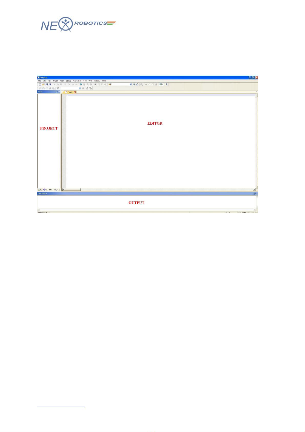
2.3 Overview of Keil µVision4 IDE
To start Keil IDE click Start>Programs>Keil µVision4. The initial screen will appear
followed by the main window.
The Keil IDE main window in basic configuration is mainly divided into three areas.
Editor - It is the area where .c and .h files of the project are edited.
Project Explorer- It shows the project tree.
Output Window- This window shows the messages related to compiling, project
building and debugging.
NEX Robotics Pvt. Ltd. 17
www.ne -robotics.com

LPC2148 DEVELOPMENT BOARD
2.3.1 Cre te Project in Keil for LPC2148 development bo rd
1. To create a new project, Select Project>New uVision Project from the main menu.
2. Create a new directory and name it as First_Project. Click open to enter in to this
directory.
NEX Robotics Pvt. Ltd. 18
www.ne -robotics.com

LPC2148 DEVELOPMENT BOARD
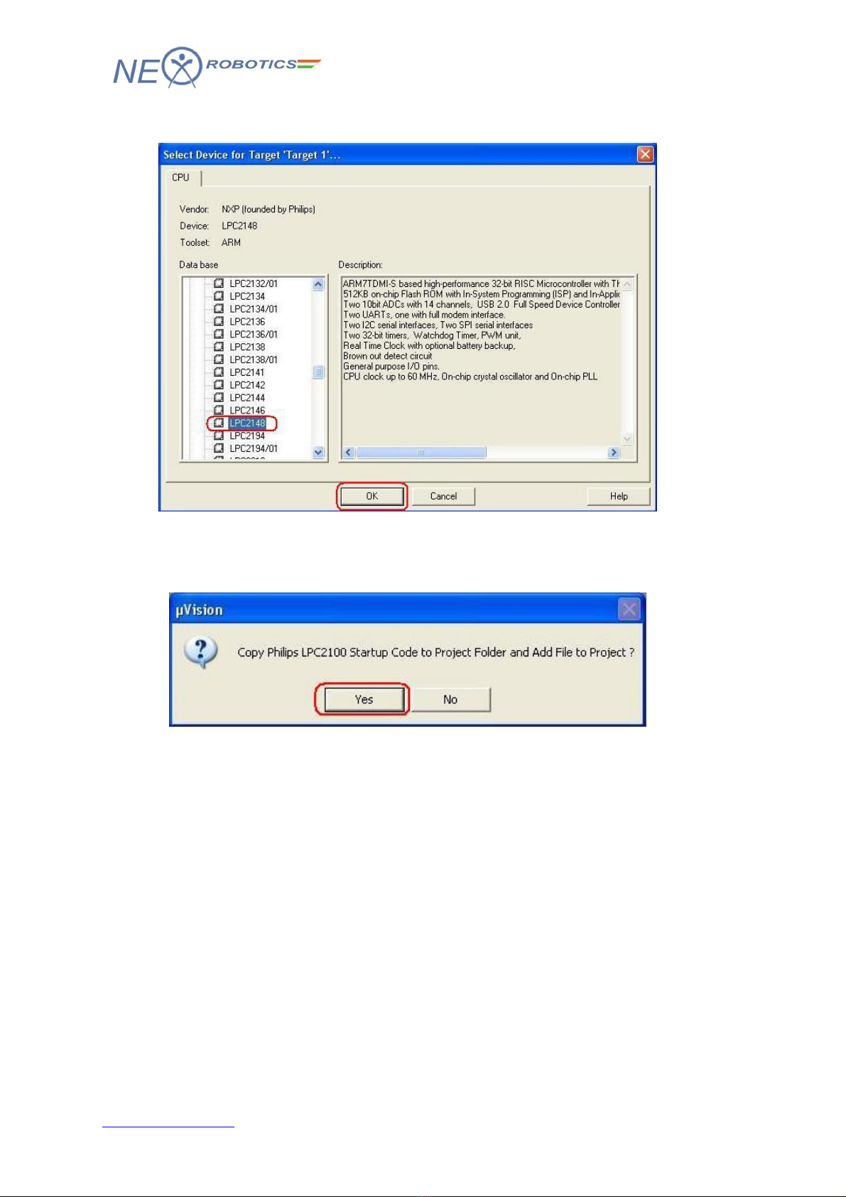
5. Now select target device as LPC2148 and click OK to continue.
6. Click Yes to copy St rtup.s file to project folder. This file configures stack, PLL and
maps memory as per the configurations in the wizard. It is discussed in the later sections.
NEX Robotics Pvt. Ltd. 20
www.ne -robotics.com
Table of contents


