ECS Electronics SI54P AIO User manual


S
l
5
4
P
AI
O
U
se
r
'
s
M
a
nu
a
l
(
fo
r
Phoe
ni
x
B
I
OS
)

ii
All brand and product names used
in
this manual may be trademarks or
regis
tered trademarks of their respective
companies
.
Trademarks

iii
B
u
il
t
-
i
n
B
I
O
S
SETU
P
P
rog
ra
m
·
SETUP Program 9
System
S
etup 10
Fixed Disk
Se
tu
p
11
Advanced System Setup
13
I
nt
e
grated
P
e
rip
h
erals
1
4
Memory Cac
h
e
1
5
Me
mory
Shad
o
w 18
Advanced
C
hipset Control 19
PC
I Devices 23
Boot Options
2
6
S
ec
u
rity Setup
2
7
Green PC Feature
:
2
8
Load ROM
Defau
l
t
V
alues
3
1
Load
Valu
es from
C
MOS
'3
2
S
ave
V
al
u
es to CM
O
S
33
Quitting Setup 34
Jump
e
r
Se
tt
i
ng
s
a
nd
C
onn
e
ctor
s
Setting the Jumpers
5
Connect
o
rs 7
Board Layouts
:
8
S
y
s
te
m
M
e
mory
Cac
h
e Memory
S
ubsystems
5
I
n
trod
u
cti
o
n
General
Specificati
o
ns
1
S
y
stem Chipset 2
II
Co
nt
e
nt
s
1
Po
w
er
K
e
y
l
oc
k
&
Po
w
er
LED
Hard
w
ar
e
R
e
se
t
S
peaker
Turbo
LED
Turbo
S
witch
S
u
s
pend
HDD
LED
Bab
y
-
A
T
4
layers
Intel Pentiumn.t
75/90/l
00
S
i
s
8
5C501
(PCl/I
S
A
Cache
M
e
mory
Controll
e
r)
S
i
S
8
5C50
2
(
PCI
Local Data
Buff
e
r)
S
i
S
8
5
C
50
3
(PCI
Sy
s
tem
1/0)
CMD
PCI06
4
0B
(PCI
Bu
s
IDE
Controller)
S
M
C
3
7C665 (Super 1/0 Controller)
UM
C
8
2C865 (1/0
TIL
Integration)
2
56/51
2
KB
or
1
MB
cache
supporting
vvrit
e
ba
ck or
vvrit
e-through policies
2
banks
of
DRAM with
memory
size
capacity of
up
t
o
1
28
MB
,
a
l
l
s
upporting
doubl
e
-sided SIMMs
\
Phoenix
Four
1
6-bit
ISA
s
lots
Four
PCI
s
l
o
t
s
PCB
:
F
o
rm
F
a
ctor
:
Con
necto
r
s:
S
l
ots
:
BIO
S:
M
e
m
o
ry
S
ize
:
Ext
e
rna
l
C
a
c
he
:
Ch
l
ps
e
t
:
1.1
Genera
l
Spec
i
fica
ti
ons
Process
o
r:
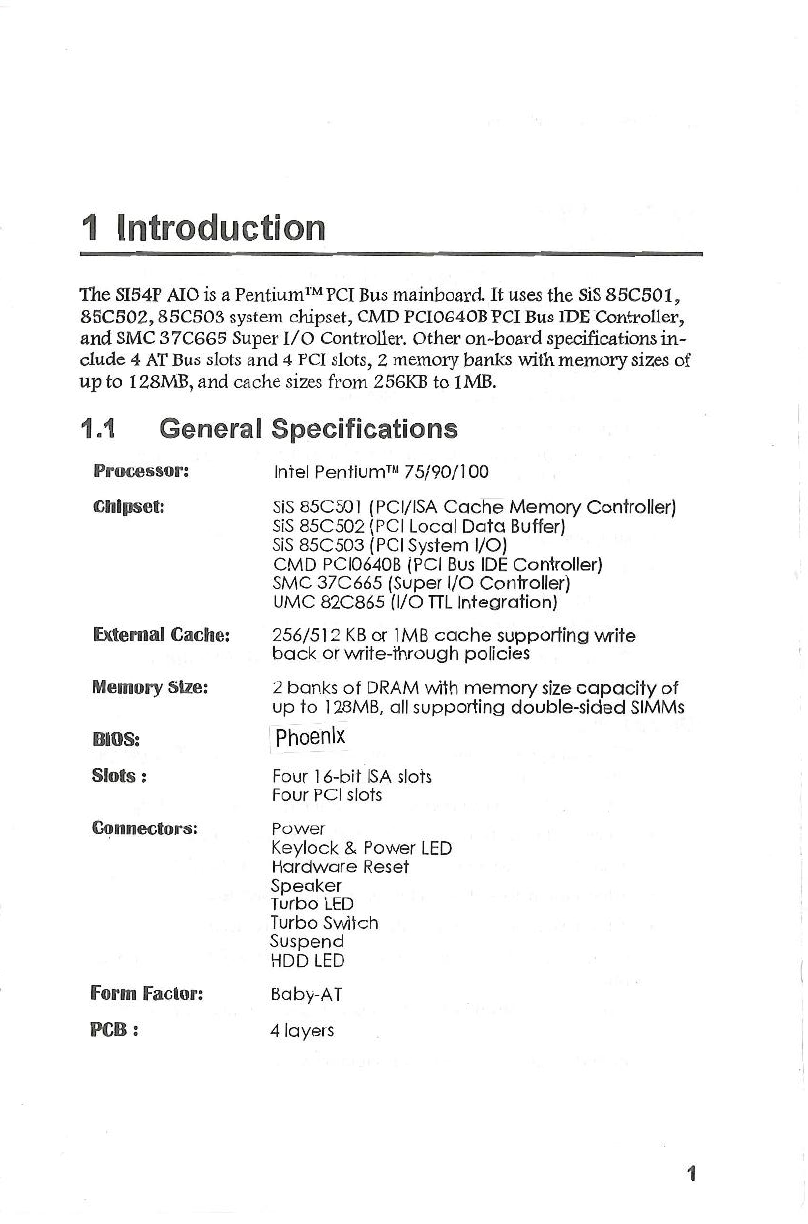
The
SI5
4
P
AIO is a Pentium TM PCI Bus
mainbo
a
rd,
It
uses the
SiS
85C501
,
8
5C
50
2
, 85C503
s
y
s
tem
chipset
,
CMD
PCI06
4
0B PCI Bus IDETuntroller,
and
SMC
3
7
C66
5
Sup
er
1/0
Cont
r
oller
.
Other
on
board
specifications
in
-
clud
e 4
A
T
Bu
s
s
l
o
t
s
a
nd
4 PCI
s
l
o
ts, 2
m
e
mory banks with memory
si
zes of
up
to
1
2
8MB
,
an
d
ca
c
h
e
s
i
z
es from
2
56KB to lMB.
1
Introduction

2
•
S
I
S8
5C502
•
Thre
e
int
e
grated
p
os
t
ed write
b
uffer
s
and
two
read
buffers increase
s
ystem
p
e
rforman
ce
•
1
level
Cl'Ut
o
M
e
m
pos
te
d
wr
ite buffer with 4 Qwords deep
• 4 levels
CPU
t
o
PCI
p
o
s
t
ed
writ
e buffer with 4 Dwords deep
•
1
level
PCI
to
Mern
p
o
s
ted
w
rit
e buffer with
1
Qword deep
•
1
level
M
e
m
to
Cl'U
r
ead
buff
e
r
with
1
Qword
d
e
ep
•
1
lev
e
l
Me
mtoPCl
r
ea
d
buffe
r
with
1
Qwo
r
d
d
e
ep
• Provides a
64
bit
P
e
nti
u
m
TM
,
DRAM
d
at
a bus
and
3
2
bit PCI data
bus
•
Operate
s
sy
n
c
hron
o
u
s
l
y
t
o
th
e
G
G.
7
MH
z CPU
and
33
.
3MHz PCI
clocks
•
P
r
ovides
p
a
rit
y
g
ener
ati
on for
memor
y writes
S
y
ste
m
C
hip
se
t
•
S
I
S8
5C501
•
Support
s
Pen
t
ium
'
?"
p
ro
c
e
s
s
or
a
t
5
9
/
GO!GG
MHz bus speed
•
Inte
gr
at
e
d
s
ec
ond
lev
e
l
(L
Z
)
ca
c
he
mod
es
•
write
through
and
writeb
a
ck
ca
ch
e modes
•
dire
c
t
mapp
e
d
o
rgani
zation
•
support
s
standard
a
nd
bur
s
t
SRAM
s
•
s
upport
s
1
Z8
KB
t
o
Z
MB
cach
e
s
i
z
es
•
c
a
che
r
ea
d
/
w
r
it
e
cy
cl
e of
3Z
Z
Z
or
4
3
3
3
u
s
ing standard
SRAM at 6GMHz
• Integrated DRAM
c
ontroll
e
r
• supports
Z
MB to
1
Z
8MB of
c
ac
heable main memory
•
1
level
po
s
ted
w
rit
e
bu
ffe
r
o
f 4
Q
wo
rds deep
•
concu
r
rent
write
bac
k
•
CAS
#
before
RAS#
t
ra
nsp
ar
ent DRAM refresh
•
Z
5GK/
lM/ 4M/
1
GM
*
N
70n
s
fa
s
t
p
a
ge mode DRAM support
• programmable DRAM
s
pe
e
d
Sl54P AIO
User
's
Manual

3
•
SM
C3JC665
• Super
I/O
controller
•
Two
I6C550
c
omp
a
tible
UART
s
• One
multi
mod
e
p
a
rallel
p
o
rt
which include
EPP
and
ECP
support
•
CMD
PC
I0
640B
• Fully
compatibl
e with the
lat
es
t PCI IDE
and
ATAPI specifications
• The
mo
s
t
compl
e
te
3
2
bit driver support
in
the industry (DOS,
Windows 3.1
Pa
s
t Disk, Windows NT,
OSIZ
,
Novell
&
SCO Unix
32bit
driver support)
·
•
Progr
a
mm
a
ble
d
a
t
a transfer timing supports customized setting for
4 IDE devices
•
Read
ahead and writeback buffers enhance transfer rates
and
al
low concurrent
operation
s
•
Suitable for PCI motherboard or PCI expansion card applications
• Fully supports and
s
urpa
ss
es
enhance IDE ModeS
•
Support
s
progr
a
m
I/O
fun
c
tion
•
S
I
S85C503
•
Integrated
brid
ge between PCI Bus and
ISA
Bus
•
translates PCI
Bu
s
cycles into
ISA
Bus cycles
•
tran
s
lat
es
ISA
m
as
te
r
or DMA cycles into PCI Bus cycles
•
provid
es
PCIto
lSA
memor
y one Dword posted write buffer
• Integr
a
ted
ISA
Bu
s
c
ompatible logic
•
Supports
rerout
a
bility of four PCI interrupts to any unused IRQ
in
terrupt
• Supports Flash ROM
SJ54P AJO
User
'
s
Manual

4
Ta
ble
2
1
.
Memory
Confi
g
uration
s and
Requirement
s
Ba
n
k
O
Ba
nk1
T
o
ta
l
S
IM
3
S
IM
4
!
SIM1
S
IM
2 M
em
o
ry
S
i
ze
25
6K
x 36
256
K
~
_
36
.
J
.
N
o
ne
None
2
MB
25
6K
x
3
6
256
K
x
36
I
25
6
K
x
36
25
6Kx
36 4MB
·
-
-
·
·
r
~
·
5
1
2
K
x 36
512K
x
3
6
;
N
o
ne
None
4
MB
i
5
12K
x 36
5
1
2
K
x 36
I
5
1
2
K
x 36
5
1
2
K
x 36
8M
B
i
!
5
1
2
K
x 36
I
5
1
2
K
~
~
4
M
x
36
4
M
x36
36
M
B
1M x 36 1M
x
36
I
Non
e
None
8
MB
I
-
-
_ _
_
L
-
--
1M
x 36
1
M
x 36
i
1
M
x
36
1M
x
36 16MB
1M
x
3
6
1M
x36
·
-
1
4M
x36
4
M
x
36
36
MB
2
M
x36
2
M
x
36
None None
16MB
2M
x
36
2
M
x
3
6 2
M
x36
2M
x
36 32MB
2
M
x36
2
M
x 36
4
M
x
36
4
M
x
36
48
MB
·
·
-·
-
·
-
· f·
-
·
-·
·
4M
x
36
4M
x 36
I
4
M
x36
4
M
x
36
64M
B
8M
x
36
8
M
x
3
~
N
on
e
Non
e
64
MB
8
M
x
36
8M
x36
I
8
M
x36
8M
x
36
1
28
MB
I
S
I5
4P
AI
O
acce
pt
s
a minimum
o
f
2
MB a
nd a
maxim
um
o
f
1
28
MB
on
bo
ard.
Th
e
r
e
a
re
t
wo
m
e
m
ory banks
w
hi
c
h
s
upp
ort
2
56/
5
1
2
KB
o
r
1/
2/4
/8/
16 MB
72
pin
ty
p
e,
s
in
g
le
and
/
or
double
d
e
n
s
ity modules.
Important
:
DRAM
in
se
rtion on
e
very bank should com
e
in
p
a
ir
a
nd
of
the same type. For instance,
if
you only
ha
v
e
two
DRAM module
s,
you cannot
in
s
tall one
DR
AM
modul
e
in
s
ocket SIM1
a
nd another
DR
AM
modul
e
of
t
h
e
sa
m
e
type on S
IM3
.
Likewise
,
memory type mixing
i
s
N
OT
a
l
low
e
d within
a
ba
nk
.
Th
e following
tabl
e
lis
t
s
all
th
e
po
ss
ib
l
e
DRAM
mo
dule
combin
a
tions
a
n
d
th
e
t
otal
m
e
mor
y
am
o
un
t
for
eac
h
op
tion.
2
S
y
s
tem Memory
SJ
54P
AJ
O
User
'
s
Ma
n
ua
l

5
Ta
b
l
e
4
1
.
Jumper
S
ett
i
ngs (Continued
..
..
.)
F
unction
Jum
pe
r
S
ett
i
ng
s
50MHz (for
7
5MH
z CPU)
J
P7
s
hort 2-3, 5-6, 7-8
CP
U
C
lo
c
k
S
el
e
ct
6
0MHz (for
90
MH
z CPU)
J
P7 short
2
-3, 4-5
,
8-9
66MH
z (for
100MH
z CPU)
J
P7
s
hort
1-
2,
5
-
6
,
7-8
Internal
Cach
e
Write-back
J
P
1
2
s
hort
1
-2
Interna
l
C
a
che
Write
-
J
P
1
2
short
2
-3
CP
U
S
i
g
n
al
Se
l
ec
t
t
hrough
Always invalidated
J
P
1
4 short
1-
2
Writ
e
to
i
nvalid
a
ted
J
P
1
4 short
2
-
3
2
56KB (with
3
2
Kx8
J
P
11
open
SRAMs)
J
P
10 open
E
xt
e
rn
a
l
Ca
ch
e 51
2
KB
(with
64
Kx8 JP11 short
M
e
mo
r
y
Sett
ing
s
SRAM
s
)
J
P
10 open
1
MB
(w
i
th
128
Kx8 SRAMs)
J
P11
short
JP10short
Th
e
tabl
e
b
e
low
summ
a
r
izes
th
e
function
s
a
nd
jump
e
r
sett
ings on
th
e
SIS4
P
AIO.
.
3.1
Sett
i
ng
t
h
e
Jumpers
3
Jumper
Settings and Connectors
T
a
b
l
e
2
2.
S
econd Level Cache Memory
C
onfigurat
i
ons
C
a
c
he
S
i
ze
Di
rt
y
RA
M
TAG
RA
M
D
a
t
a
(
U
23
-
26
)
(U28
)
(U
27
)
(U
34-
U
3
7)
2
56KB
3
2
Kx8 (5V) 32Kx8
(
5V) 32Kx8
(
3.3V)
51
2
KB
3
2
Kx8 (5V) 32Kx8 (5V) 64Kx8
(3
.
3V)
1MB
3
2Kx8
(
5
V) 32Kx8 (5V) 128Kx8
(3
.
3V)
Cac
h
e
M
e
m
o
ry
S
u
bsys
t
e
m
s
SJ
54
P AIO User's Manual

If
a flash ROM is installed on the mainboard,
plea
s
e
r
e
fer to the
R
E
ADM
E.
DOC file in the Flash Utility
di
s
ke
tte
before programming the
F
lash ROM
B
I
OS
.
Befo
r
e
installing the driver
for
on
board PC
/
/DE
(
G
M
O
P
C/064
0B), consult
th
e
readme fife in the
G
MO
D
riv
e
r
Diskette
.
1
.
J
P
B
open for
E
P
R
OM and
F
l
a
sh ROM normal
u
s
e.
2
.
ltllhen you update your system
B
IO
S with
F
lash ROM
utility, please set the
J
P
B
to short
1
2 for
+5
V
F
l
a
sh
R
O
M or
J
P
B
to short
2
3 for
+
1
2
V
F
l
ash ROM.
3.
After
upd
a
ted
t
he system
B
IO
S
,
you should remove
the jumper
JPB
.
6
No
t
e3
:
No
t
e2
:
T
able
4
1
.
Jumper
S
ett
i
ngs
No
t
e1
:
F
unction
Jum
p
e
r
S
ett
in
g
s
For Progr
a
mming
Fl
as
h
ROM
J
P
S
s
hort
1-
2
(+SV)
u
se
d
RO
M
B
I
O
SS
e
lection For Programming
Fl
as
h
R
OM
J
PS
s
hort
2
-3
(
+
12V)
u
se
d
EPROM
.
J
PS
op
en
En
a
bl
e
ID
E
J
P
4
op
en
O
n
-
bo
a
rd
PC
I I
DE
Di
s
a
bl
e
IDE
J
P
4
s
hort
E
n
a
bl
ed
J
P3
s
hort
1
-2
O
n
-
bo
a
rd
1/
0
Di
sa
b
l
ed J P3
s
hort
2
-
3
E
CP
M
ode P
a
r
a
llel Port DRQ1 J
P
1
short
1
-
2
DACK1
Select
i
on
J P2 short
2
-3
E
CP
Mod
e
ECP Mode
Para
ll
el Port DRQ3
J
P1
short
2
-3
DA
CK
3
S
e
l
ec
tion
J
P2s
hort1-
2
E
nabl
ed
J
PS
s
hort
DRA
M
Par
ity
C
h
eck
Di
sa
bled
J
PS
op
en
All
SIMM
s
are
s
ingle
de
n
s
ity
J
P
5
short
2-
3
modul
es
Me
mo
r
y
Se
l
e
ct All
SIM
Ms
a
r
e
doubl
e
d
e
n
s
ity
modul
e
s
or SIMMs
3/
4 are
doub
l
e
dens
ity
and SIMMs
1
/
2 J
P
5
sho
rt
1
-
2, 3-4
ar
e
s
i
ngl
e
de
ns
it
y
SJ
54P AIO
Use
r
'
s
M
anu
a
l

7
pin
2
-3
:
Tu
r
bo
LED
p
i
n
4
-5:
S
usp
e
nd
Pu
s
h Button
(SM
I
)
P
I
N
6-7
:
Turbo
Swit
c
h
p
i
n
9
-
10:
Hardwar
e
R
es
et
pin
1 1
-
1
3
:
System
Po
we
r
LED
& pin
1
4
-
1
5
K
e
ylock
pin
17
-
20
:
Sp
e
ak
e
r
Note
:
J1
3 {pin6
7),
Turbo
S
witch
F
unction
P
rocedure:
a
.
S
hort
2
3 for the jumper setting
of
J
P
12
.
b
.
S
e
t
the
L
1
Cache Update Mode into
(
WT) Write
Through
with
i
n the
BI
OS
C
hi
pset Features
SE
TUP
.
c.
After
fin
i
sh
i
ng Steps a
&
b
,
the H/Wturbo switch
w
ill
.
function
norma
l
and the Turbo
L
E
D
wi
ll
turn on/off when
system in the
Turbo/De
turbo mode.
T
B
.
L
ED
S
MI
TB
.
S
W
R
e
s
e
t
1 1
1
2 13 14
1
5 16 17
1
8
1
9
2
0
®085800000
'
~~~9~9Q~9a
AT
Keyboard
Conn
e
ctor
Pow
e
r
Conn
e
ctor
Floppy
Conn
e
cto
r
COM
l
Port
Conn
ec
tor
C
OM2
Port
Conn
ec
tor
Print
e
r
Port
Conn
ec
tor
I
DE
Primary
Conn
ec
tor
I
DE
Secondary
Conn
e
ctor
Pow
e
r
Conn
e
ctor (For
3.
3V)
HDD
LED
C
onn
e
ctor
2X
1
0
JUMP
E
R
B
LOCK
r===
KEYLO
C
K
==-1
J2
J4
J5
J6
J7
J8
J9
JlO
Jll
J
l
2
Jl
3
Fun
c
ti
o
n
Co
n
nec
t
o
r
There
are
several
conne
ct
ors located on
the
SI5
4
P
AIO
.
Their functions
ar
e
list
e
d
below
.
3.2 Connectors
SJ5
4
PAIO
User's Manual

8
Figure
4
1.
S/54P AIO Mainboard Layout
Co
nn
e
ctor
SiS
85C501
SiS
85C
5
02
J1
3
Pentium™
CPU Socket
.P.>~
1
l
=3
GND
--
--
l§j=3
+3
.
3V
Pow
e
r
Supply
SiS
85C503
m
'"
$>
7
0
963
Ba
nkO
Ba
nk1
CMD
•
• • •
PCI0640
-
ii'i
cb
w
e
0
(i)
c
0
'iii
c
C'll
x
w
0
(i)
c
0
'iii
c
C'll
x
w
0
(i)
c
0
'
iii
c
C'll
.n
-
ii'i
<b
p
p p
c
c c
I
I I
# # #
1
2
3
SMC
U
M
8
2C
37
C
6
66
866
F
Jl
PS
/2
DALLAS
DS12887A
0
(i)
c
0
'iii
c
C'll
.n
-
ii'i
I
(0
\
1
~~Ag
~f~8
f~I~
+
§i
.
~
&.Ii~
Ru
t
t
ICOLED
'
3
.
3
Boa
r
d
La
y
o
ut
s
SJ5
4
P AIO
Use
rs
M
a
nu
a
l

9
•
Fixed
Disk
Setup-
allows for automatic detection of the hard disk drive
typ
e
(s) including the number of cylinders and heads,
writ
e
pr
e
compen
s
ati
on
time
,
read/writ
e
he
a
d
landin
g
zone, and number
of
sectors per
tr
ac
k.
Also switches the LBA Mode feature
of
the hard disk to on
o
r
off
.
•
AdVanced
System
S
etup
-
sets the various system options for the user,
in
cluding the Integrated
P
e
riphe
r
als
,
M
e
mory Cache, Memory
S
hadow
,
Advan
c
ed Chipset
Contro
l
,
and PCI
Devices
.
•
B
oot
OpUons
-
d
e
t
e
rmin
e
s
th
e
s
e
quenc
e with which
th
e
syst
e
m will
pr
o
ceed
wh
e
n booting
th
e
op
e
rat
i
n
g
s
ys
tem.
On
-
screen
i
nst
r
uct
i
o
ns at the bottom of
eac
h
screen ex-
plain
h
o
w to use the program
.
•
System
Se
tup-
allow
s
c
hecking or modification
of
general configuration
inform
ati
on
.
Note:
F
i
gure
4
-1
.
SETUP
Mai
n
Menu
It
is
highl
y
r
e
commended
th
a
t
y
ou list down all the values of the
SLTUP
pro
gram
befor
e making any
ch
a
nges
.
Doing
s
o
will
save a lot of time restoring
th
e
s
y
s
tem back
in
the
ev
e
nt of a
confi
g
uration memory
loss
.
Phoeni
x
S
e
tu
p
-
Co
pyrigh
t
1'985-
9
4
Ph
oe
ni
x
Technologi
es
Ltd
.
Ma
in
11e
nu
.
Syste111
Se
t
u
p
Yl
xed
D
i
s
k
Se
tup
•
Ad
u
a
n
ced
S
y
s
te
rw.
S
et
u
p
Bo
o
t
O
p
t
i
on
s
•
Sec
ur-
i
t
y
S
e
tup
•
Gr
ee
n
re
F
ea
tu
re
Lo
a
d
R Cl1
D
e
f
a
ul
t
Va
lu
e
s
Loa
d
U
a
l
u
es
fr
on
Cl'IOS
Sa
v
e
V
a
l
u
es
t
o
C
M
OS
Tl
l'lo
u
e
E
nt
e
r
Se
l
ec
t
Fl Help
E
SC
Ex
it
F10
Sa
vc
B:t:xi
t
4
.
1
SE
TU
P P
rogram
4
B
uil
t-
i
n
B
I
OS SETUP Program

10
Figure
4
-
2.
S
ystem Setup Screen
P
hoe
ni
x
Setup - Copyright 1985-91 Phoenix
Tech
n
alogies Ltd..
Sys
te~ Setup
Syst
e
rt
T
l
t1e
:
[16:513:591
S
ys
te
A
Dat
e:
[0
4/
01
/
19!'1'1
l
V
ideo
Syste
11
:
[EGA
/
VGAI
Syst
ert
Me
t!!
ory
:
6
4
0
K B
Extended
He
110
ry:
7
MB
Dis
H
ette
Dri
ve
A
:
[1.2
MB.
5%"1
Dtsk
t:
tte
Dr-l
UC"::
B: [Hot lns te
l
I
e
d I
Keybodro:
[ln
s
tdlledl
f
.I.
tto
u
e
ESC
Exit
PgUp
Pr
e
viou
s
V
a
lu
e
FS
Previous Conf igura.t ion
Fl
H
e
lp
PgD
n
Nex
t
U
a
lu
e
F6
D
e
fault
Conf
iguratton
4
.
2
S
y
s
te
m
Se
tup
•
Sec
u
r
i
ty
S
e
tup-
provides special access for the
us
e
r to
ent
e
r
th
e
o
pe
rat
ing system and Setup program, and restricts unauthorized access to
th
e
floppy disk drives.
•
Gra
a
n
PC
Faablras
-
allows the timer ssttinqs for the
DOZE
,
STANDBY and RESUME modes.
It
also lists the SMI events by
which the system wakes up from
S
T AND BY or SUSPEND
modes. If the device
is
not
active
,
Power Management Function
will slow down the CPU speed and bathe
ID
E
and monitor will be
put into doze, standby, or suspend mode.
•
L
oad
ROM
De
f
a
u
lt
Va
lu
as
-
allows for automatic
c
onfigurat
ion of all the
above options using the values stored
in
the ROM
B
IO
S
table.
•
Load
Val
u
es
fr
o
m
CMOS
-
allows for automatic configuration
of
all the
above options using the
p
r
evious
value
s
stored
in
th
e
CMO
S S
RAM.
•
Sava
Va
l
ues
t
o
CMOS
-
saves the
chang
e
s you have made in the
SE
TUP
program, then exits and reboots the system.
To choose
an
item from the
SETIJP
main menu, move the cursor using the
<Up
> and
<Down
> arrow keys and press
<
Enter>.
Sl54P AIO User's Manual

11
F
i
gu
re
4
-
3
.
F
i
xed
D
i
sk
Set
up
S
cr
ee
n
1
P
hoe
n
i
x
Setup - Copyright
1
985-91 Phoenix
Tec
h
no
l
og
i
es
Ltd
.
F
i
xed
Di
s
k
S
et
up
ID
E
Adapter
e
!last
er
CC
:
541 Mbl
IDE
Adopt
e
r
e
Slave
(Ha
ne
l
IDE
Ad.dpt er
1
rla.
s
tel"
(Hone
)
ID
E
Adopter
1
Slove
(
Ha
ne
l
Lar-q
e
Di
sk Access
ftOde
:
[
En
a
b
l
ed]
H
llo
ve
Enter
Se
l
e
ct
Fl
He
l
p
ESC
Ex
i
t
F10
Sa
u
e
llEx
l
t
The Fixed Disk Setup provides auto configuration of the
hard
drive
insta
ll
ed
in the
system
.
After pressing the <Enter> key on this item in
the main
menu, the
following screen i
s
displayed.
4
.
3
F
i
xe
d
D
i
s
k
S
etup
KeVboanl
-
selects
Install/
Not Installed
for
keyboard device
setting
.
Diskette
DrlVe
A:/B
:
-
specify the capacity
and
format of the floppy drives
in
sta
ll
ed
in
your system
.
Video
Splem
-
specifies the display adapter
insta
ll
ed.
Splam
/
Extended
Memorv
-
displays important
inf
o
rmation
ab
o
ut your
sys
tem configuration which includes the system
and
extended
me
mo
ry
sizes
.
They
are
updated
autom
a
tic
a
lly by the
SETUP
program
according to the
status detected by the BIOS
self
test. This section
o
f
t
he System
Set
u
p screen
is for viewing purpose only and
ma
nu
al
modificati
o
ns are not
a
llo
wed.
Splem Dale
-
allows
manu
a
l setting of the electronic calendar
on the main
board.
Splem
Time
-
sets the system's internal clock which includes
ho
ur,
min-
utes,
a
n
d
seconds
.
S
l
54P AIO
U
ser's
M
a
nu
a
l

12
Landing
Zona
-
refers to the cylinder
number
where the disk drive heads
(read
/
write) are positioned to when the disk drive
i
s
parked.
F
i
gure
4-4
.
F
i
xed Disk Setup Screen
2
AUIOIVPe
Fixed
Disk
-
detects the type of fixed disk 0
and/
or
1
inst
a
lled
.
If
successful, it
fills
the remaining fields on this
menu
.
Type
-
1
to
4
5
fill
the
remainin
g fields
wi
t
h
values for
pred
e
fined
di
s
k
drives
.
"User" allows the
use
r
to
fill in
th
e remaining
fields
.
"
Auto
"
allows
the system auto detect IDE HDD Func
tion
,
if
you
a
lr
ea
dy
inst
a
ll
ID
E
HDD.
CVllnders
-
specifies the
numb
e
r
of
cylinder
s
of the
hard
dis
k
d
riv
e.
Heads
-
specifies the number
o
f
r
ea
d/w
ri
te heads of the
h
a
rd
disk drive.
Seclors/Track
-
provides the number of sectors per track defined for the
hard
disk
drive
.
Ph
o
e
n
ix
Se
tup -
Co
pyr
ig
ht
l
'J
B
S-
94
Pho
e
ni
x Tec
~TIJ
l
o
g
I
es
Ltd
.
Fi
x
ed
Di
s
k 0
Control
CBoot
Dr
i
vel
Auto
t
yp
e
Fi
xed
Di
s
k
:
[
P
re
s
s
Ent
e
r
1
T
ype
:
[U
se
r]
Cylinders
:
[
667
]
Heads:
[
Bl
Sectors/Track
:
[ 33]
Wr
l te
preec
ep
:
[Nonel
ll
llltl
Sec
to
r
Tr
a
n
s
f
ers: !Disabled]
L
HA
"
ode
.
Co
ntra
I
:
[Di
s
abled]
3Z
Di
t
l;O
:
!Di
s
abled]
U
llovc
Ente
r
S
e
l
e
ct
Fl
Help
ESC
Ex
it
rre
Sau
e<'!
E
x
l
t
If
the program fails to
d
e
tect
t
h
e
hard
disk type(s) or
th
e <Enter> key
wa
s
not pressed
in
the Autotype Fixed
Di
s
k
option
,
manu
a
l
se
tting of
th
e values
is recommended.
Once the program detects
th
e
typ
e of
hard
disk 0
and/
or
1
inst
a
lled
,
it
will
display the relative information such
a
s
the type,
cylinder
,
h
ea
ds
,
write pre
compensation
,
landing
zone
,
numb
e
r
of sectors per track,
an
d the
LBA
mod
e control.
Sl
5
4P AIO User's Manual

13
F
i
gure
4
-
5.
Adva
nc
ed System Setup Screen
Phoeni
x
Se
tup Copy.right 198594
Phoeni
x
Techno
l
ogie
s
Ltd
.
Adva
n
ce
d S
y
st.ea Se tup
Uarn
l
ng
r
Jtens
on
thi
s
ne
nu
,
if
se
t
in
correctly
,
could
ca
u
se
y
o
ur
s
y
st.e.. to
e
e
lr
unct.
Ion
.
l
rr
tegre
t
ed
Per
i
ph
e
ra
l
s
M
e
nary
Ca
che
•
11e
n
o
ry
Sh
a
do
u
•
Ad
1J c
rnc
ed
Chip
se
t
C
ontrol
P C
I
D
c
ul
ccs
ti
trov
e
E
n
te
r
S
e
l
ec
t
F1
H
e
lp
E
S
C
E
x
it
F10
S
dueM:x
il
The Advanced
S
ystem Setup
allow
s
the user
t
o program five main groups of
parameters
namel
y
t
h
e Integrated
Periphera
l
s, Memory Cache, Memory
Shadow, Advanced Chipset Control, and PCI Devices. This BIOS Setup
pa
rameter
is
designed for programmers who
wis
h
to fine tune the on
board
chipset
.
4.4
Ad
v
a
n
ced
S
ystem
S
etup
M
u
Id-Sector
Trans
f
ers
-
determines the number of sectors per block for
multiple sector transfers. The available options are
Z/
4/8/1
6
sectors
,
"Auto"
which refers
t
o
t
h
e size the disk returns when queried, and
"Dis
abled"
(defau
l
t)
.
lBA
Mo
d
e Co
n
tro
l
-
tu
rns on or off the hard disk drive's
LBA
Mode
support
.
Some HDD sizes support more
than
540MB and the
LBA
mode for data
transfer
.
If
your
hard
disk supports
LBA
mode, you should enable (on) this
option otherwise disable (off)
it
.
32
8
111/
0
-
it is only for PCI IDE card,
if
you want to use the
ISA
IDE
card
,
you have to disable it.
Write
Preco
m
p
-
refers to the cylinder number,
ab
o
ve which, disk drive op
erations require reduced write current. Also specifies
t
h
e number of cylin
ders at which to change the write timing.
Large
D
i
sk
Access
Mode
-
for Large Hard Disk Compatibility
(
l
arger than
5Z8MB)
issues
,
you must enable this item except when
running
the system
under UNIX. The default setting ofthis option
i
s
"Disabled."
S
l
54P
A
IO User's
Ma
nu
a
l

1
4
LPT
Pon
-
assigns the
a
ddr
ess of
t
h
e
p
a
r
a
lle
l
p
o
rt
on
boa
r
d. This
o
ption also
prevents the
sy
stem from
e
ncountering
a
ny conflict
w
h
e
n
an
add
on
c
a
rd
with
_E
ar
a
lle
l port
i
s
in
s
talled in the
future
.
The a
vail
a
ble options are:
•
E
na
b
l
e
d
(
d
e
f
a
ul
t
)
•
D
i
s
a
b
l
e
d
Diskette
CODlrOll
e
r
-
s
et
s
the diskette controller mode of the SMC 3
7
C66
5
I/
0
chip to either on
o
r
off
.
The a
v
ailable options
a
re:
•
E
n
a
b
l
e
d
(
d
e
f
a
u
l
t
)
•
D
i
s
a
b
l
e
d
F
i
gure
4
-
6
.
In
tegrated Per
i
p
he
ra
l
s
Sc
r
ee
n
CO
M
1
/
2
Pon
-
assign
th
e
a
ddresses of
th
e primary and secondary serial
ports
on
bo
ar
d.
The
avail
a
ble
option
s
a
re
:
•
E
nab
l
ed
(
de
fa
ul
t
)
•
D
i
s
a
b
l
ed
Pboe
n
i x
Se
tup -
Co
py
r
i
g
h
t
1
985
-
94
Phoen
i
x
Te
chn
ol
og
i
es
L
t
.d .
Integra
ted
Per
iph
era
l
s
CON
1
Port:
c
ll
m
W
l1
b
•
l
1
C
O
N2
Po
rt
:
c
zra
•
IR
Q
3 I
L
PT
P
o
r
t
:
[
3711
IRQ
? l
D
i
ske
tt
e
Con
t
ro
ll
er:
(En
ab
l
ed
]
LP!
Exteode
d
Node
:
[St
a.
nd
d
rd
]
CMD
E
nh
ance
d
Modr.:
:
CD
l
sa
b
l
e
dl
fl
rto
u
e
E
SC
E
xit
PgUp
Pr
evi
ou
s
Va
lu
e
F
5
Previo
us
Con
f
igurat
i
on
Fl
H
e
lp
PgDn
Ne
x
t
U
a
l
ue
F
6
D
e
f
au
l
t
Co
n
figur
a
tion
Int
e
gr
a
t
e
d
Pe
r
i
ph
e
r
a
l
s
Selectin
g
Integrated
P
eri
pherals from the Advanced
Sy
s
t
e
m Setup main
menu
displ
ays
the
following
s
creen
.
The
a
ctu
a
l
f
ea
tu
r
es
displayed
dep
e
nd
on the
ca
p
a
bilities of
y
ou
r
s
ystem
's
h
a
rdw
are
.
S
l
54P A
I
O User's
Ma
n
ua
l

15
F
i
g
u
re
4
-7
.
Memory
Ca
ch
e
S
c
reen
1
P
h
oeni
x Setup Copyright
198594
Phoeni
x
Tec
h
no
l
ogi
es
Ltd
.
t1et1
o
ry
Cach
e
E
x
ternal cache
:
l
!ilmllll'llll
l
Ll cache ur
i
te
bac
k
:
[
En
a
b
l
ed]
L2
cac
h
e
urite back:
IEnabed
l
Syste"
B
IO
S
ca.c
hea
b
l
e:
ID
l
sab
l
edl
Cache speed:
[
S
l
o
we
r
]
C
ac
he
bur
s
t
r
/
1;,1
eye
l
e:
[
3
Tl
Refresh
RAS
act
I
ue t
t
ee
:
1
6Tl
Ncn
-
cec
h
ee
b
l
e
eree
a
t.:
1D
i
s4b
l
cdl
A
I
locati
o
n
of
rxm-oac
heab
l
e
ar
-ea
u
L
:
[L
oc
a
l
DH
Artl
Region
1
1 atar-t addr-: [ ll HBl
Region
1
,
s
i
ze
:
C
61 HBl 9
U
Move
ESC
Exit
PgUp
Pre
u
tou
s
Va
l
u
e
FS
Pre
v
iou
s
Configurati
o
n
F1
f
le
lp
PgDn
liext
IJ
n
l
ue
FD
Defa
ul
t
Conf
i
gurat
io
n
Se
l
ecting the Memory Cache from the Advanced System
S
etup
m
a
in
men
u
displays the
fo
ll
owing
screens
.
The actual features displayed depend on the
capabilities of your system's
hardware
.
Memo
ry
Cac
h
e
CMD
Enhanced
Mode
-
enables
3
2 Bit
I/O
and CMD Enhanced
M
o
de to
sup
port CMD DOS
driver
.
lPT
Exte
n
ded
Mode
-
In
"ECP
&
EPP"
mode,
EPP
can select
through
the
ECR
register of
ECP
m
o
de 100.
"Standa
r
d"
mode can be selected
thr
o
ugh
the
ECR
register as mode
000
.
The
availab
l
e options are:
•
Stand
a
rd
(
defau
l
t
)
•
E
PP Mod
e
.
•
ECP Mode
•
ECP
&
EPP
S
l5
4P AIO
U
ser's
Ma
nu
a
l
Table of contents
Other ECS Electronics Motherboard manuals

ECS Electronics
ECS Electronics L7VMM3 1.0 User manual

ECS Electronics
ECS Electronics P6ISA-II User manual

ECS Electronics
ECS Electronics M847 Series User manual

ECS Electronics
ECS Electronics P6IEAT User manual

ECS Electronics
ECS Electronics 648FX-A User manual

ECS Electronics
ECS Electronics L7VTM User manual

ECS Electronics
ECS Electronics P4VXAD Rev.3.1 User manual

ECS Electronics
ECS Electronics L7VMM User manual
 User manual")
ECS Electronics
ECS Electronics 661FX-M REV:1.0(B) User manual

ECS Electronics
ECS Electronics L4IBAE User manual


