Nexen AE120 User manual

1FORM NO. L-20230-E-1107
AE120 Web Guide Amplifier
WEB CONTROL PRODUCTS
User Manual

2FORM NO. L-20230-E-1107
In accordance with Nexen’s established policy of constant product improvement, the specifications contained in this
manual are subject to change without notice. Technical data listed in this manual are based on the latest information
available at the time of printing and are also subject to change without notice.
Technical Support:
800-843-7445
(651) 484-5900
www.nexengroup.com
Nexen Group, Inc.
560 Oak Grove Parkway
Vadnais Heights, Minnesota 55127
ISO 9001 Certified
Copyright 2007 Nexen Group, Inc.
Read this manual carefully before installation and operation.
Follow Nexen's instructions and integrate this unit into your system with care.
This unit should be installed, operated and maintained by qualified personnel ONLY.
Improper installation can damage your system or cause injury or death.
Comply with all applicable codes.
WARNING

3FORM NO. L-20230-E-1107
TABLE OF CONTENTS
Introduction ----------------------------------------------------------------------------------------------------------------------------------------4
Installation ----------------------------------------------------------------------------------------------------------------------------------------- 5
Electrical Connections ------------------------------------------------------------------------------------------------------------------------5
Calibration and Adjustment -----------------------------------------------------------------------------------------------------------------7
Operation ------------------------------------------------------------------------------------------------------------------------------------------9
Troubleshooting -------------------------------------------------------------------------------------------------------------------------------10
Specifications ----------------------------------------------------------------------------------------------------------------------------------10
Warranties ---------------------------------------------------------------------------------------------------------------------------------------11
------------------------------------------------------------------------------------------------------------------------------------------------------------

4FORM NO. L-20230-E-1107
INTRODUCTION
Read this manual carefully, making full use of its explanations and instructions. The “Know How” of safe, continuous,
trouble-free operation depends on the degree of your understanding of the system and your willingness to keep all
components in proper operating condition. Pay particular attention to all NOTES, CAUTIONS, and WARNINGS to
avoid the risk of personal injury or property damage. It is important to understand that these NOTES, CAUTIONS, and
WARNINGS are not exhaustive. Nexen cannot possibly know or evaluate all conceivable methods in which service may
be performed, or the possible hazardous consequences of each method. Accordingly, anyone who uses a procedure
that is not recommended by Nexen must first satisfy themselves that neither their safety or the safety of the product will
be jeopardized by the service method selected.
Print Drum
or Cylinder
Sensor
FIGURE 2
Center Position Control (CPC)
To maintain the centerline of the web
coincident with machine centerline: A=B
FIGURE 1
Edge Position Control (EPC)
To print 1" from web edge:
Align centerline of sensor 1"
outside of printed impression.
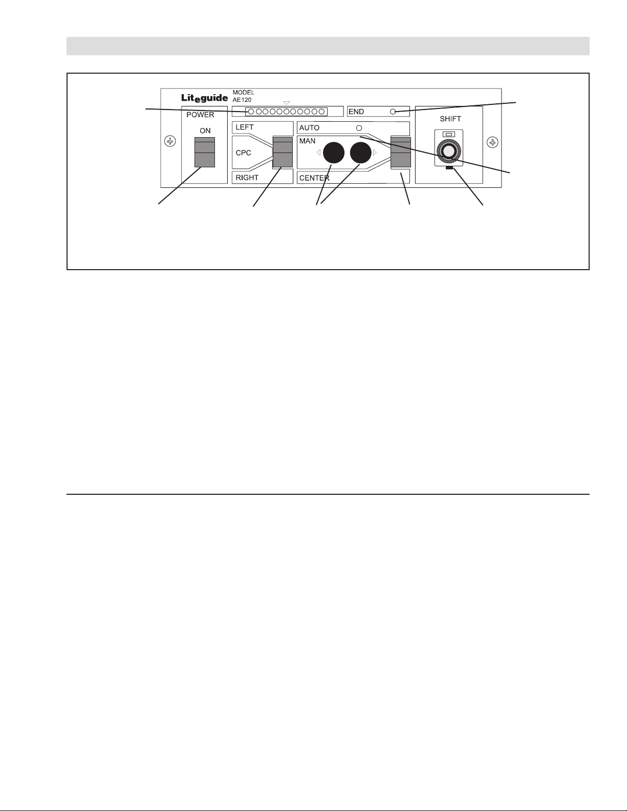
Nexen’s AE120 electronic amplifier and controller
receives web edge input signals from web guide sensors
and puts out a signal to correct the Web position within
the machine.
Edge position signals can be provided by an opaque
edge sensor (PH16 and PH46) or ultra sonic sensors
(UH21 and UH01) for transparent edges. Both types of
sensors can be mounted to control one side of the web
or Edge Position Control (EPC). Two sensors of either
type can be placed on either side of the webs to provide
Center Position Control (CPC).
With EPC, a single sensor is mounted on one side of the
web, with its measuring center aligned with the desired
position of the web edge. The primary purpose for EPC
is to maintain the edge of the web at the measuring
center of the sensor (See Figure 1).
With CPC, two sensors are mounted equally spaced
from the centerline of the machine. The primary purpose
of CPC is to maintain alignment of the web to the center
of the machine (See Figure 2).
Nexen’s AE120 can also receive inputs from several
sources:
• An Automatic Centering Sensor can be attached to
guide roll assemblies or moveable roll stands.
Nexen’s AE120 uses a Proximity Sensor (Product
No. 912696) mounted to show the mechanical
device is at its center of travel or neutral position.
• A customer supplied 10K ohm Remote Fine
Adjustment Pot can be installed to allow remote fine
adjustment of the web position.
• A Remote Controller, model RP10 (Product No.
912695) can be connected to allow remote control
with a Fine Adjustment Pot, Mode Switch, and
Manual Control Switches.
• A customer supplied switch rated at 15VDC,
250 mA, can be used as a Lock Out Switch to
momentarily disable automatic correction.
The AE120 may be used with Travel Limit Switches.
These are not required for proper functioning of the
AE120 as it is equipped with an over current protection
circuit. In installations where the guide roll design or
moveable roll stand design requires limit switches, the
Travel Limit Switches can be used to interrupt output to
the actuator motor.
The AE120 output is a bipolar, 24VDC signal, rated
at 1.2 Amp. The output of a freestanding AE120 can
be applied to a linear or rotary actuator to control web
position with a web guide assembly or a moveable roll
stand.
Nexen’s AE120 also provides the excitation voltage for
the following sensors: PH16, PH46, UH21, or UH01.
An End of Travel Alarm is also available as both a front
panel warning light and a N. O. relay contact. The End
of Travel Alarm is given when the guide roll assembly or
moveable roll stand has moved to the end of its travel
limits and could not bring the web back into correct
alignment or when the optional Travel Limit Switches are
actuated.
Process

5
FORM NO. L-20230-E-1107
INSTALLATION
Refer to Figure 3 for mounting dimensions when the
AE120 is used as a free standing Web Guide Amplifier.
FIGURE 3
Remove
screws
Terminal Block
Strain Relief
Clamps
FIGURE 4
FIGURE 5
NOTE: The AE120 is an electronic component and
should be mounted in a shock and vibration free
area which has an ambient temperature greater
than 32oF [0oC] and less than 122oF [50oC].
ELECTRICAL CONNECTIONS
When used as a stand alone Web Guide Amplifier,
make electrical connections according to the following
procedure:
1. Remove two screws on the front panel (See
Figure 4).
2. Slide the chassis out of the housing to allow access
to the Terminal Block (See Figure 5).
NOTE: All cables must be routed through the
Strain Relief Clamps (See Figure 5).

6FORM NO. L-20230-E-1107
3. Using cables provided with the sensors, make the
connections for either left hand or right hand EPC, or
CPC (See Figure 6).
4. Connect AC Power in the range of 100 to 240VAC
to Terminals 1and 2. Connect Terminal 3to ground
(See Figure 6).
5. Connect motor output lead to Terminals 4and 5.
Connect cable shield to Terminal 6(See Figure 6).
6. Connect optional Travel Limit Switches to Terminals
6, 7, and 8(See Figure 6).
NOTE: If Limit Switches are not used, short all three
terminals together.
7. Connect Automatic Centering Sensor (Product No.
912696) to Terminals 9and 10 (See Figure 6).
8. Connect the optional Lock Out Switch to Terminals
19 and 20 (See Figure 6).
NOTE: The Lock Out Switch is a customer supplied
switch rated at 15VDC, 250mA, N.O.,
momentary contact.
9. If used, connect optional RP10 Remote Controller
(Product No. 912695) to Terminals 21-23 (See
Figure 6).
10. If used, connect a customer supplied Remote Fine
Adjustment Pot, rated 10K ohm, to Terminals 21, 22,
30, and 33 (See Figure 6).
FIGURE 6
E

7
FORM NO. L-20230-E-1107
CALIBRATION AND ADJUSTMENT
FIGURE 7
End of
Travel
LED
Auto
Indicator
Fine
Adjustment
Control
Manual
Push
Buttons
Mode
Switch
Sensor
Select
Switch
Power
Switch
FIGURE 8
LAMP PHB1 GAIN 1 PHB2 GAIN 2 OUTPUT F. ADJ C. ZERO C. GAIN
NOR/REV
Switch for
MANUAL
Operation
NOR/REV
Switch for
CENTER
Operation
NOR/REV
Switch for
AUTO
Operation
Error
Indicator
SENSOR CALIBRATION
EPC Calibration
1. Set Fine Adj. Pot on the front panel to 5.0 (mid-travel)
(See Figure 7).
2. Using the Sensor Select Switch located on the front
panel, select either the RIGHT or LEFT Sensor (See
Figure 7).
3. Insert a piece of material until it completely covers the
sensing area of the sensor; then, remove the material.
The Error Indicator array will light up to show
maximum and minimum insertion with up to five red
lights on either side of the center green light (See
Figure 7).
NOTE: Use opaque material with PH16 and PH46
and soundproof material with the UH21 and
UH01.
4. Rotate the Photo Head Balance Pot (PH1B for the
left sensor and PH2B for the right sensor) until the
insertion and removal of material lights up an equal
number of red lights on either side of the green light
on the Error Indicator array (See Figures 7 and 8).
5. Rotate GAIN 1 for the left sensor and GAIN 2 for the
right sensor until the insertion of material illuminates
five red lights in either direction (See Figures 7 and 8).
CPC Calibration
1. Perform EPC Calibration separately for each sensor.
2. Set the Sensor Selector Switch to the CPC position
(See Figure 7).

8FORM NO. L-20230-E-1107
1. In Manual Mode, align the guide roll mechanism or
moveable roll stand so it is in the middle of its
mechanical travel or neutral position.
2. Align the Automatic Centering Sensor with its
magnetic trigger to give as near zero output as
possible, measured at Terminals 9and 10.
OUTPUT GAIN ADJUSTMENT
1. If the guide roll mechanism or roll stand hunts or
oscillates while the AE120 is operating in
Automatic Mode, rotate the Output Gain Pot
(OUTPUT) counterclockwise until hunting stops
(See Figure 8).
FINE ADJUSTMENT TRIM
1. One rotation (360 degrees) on the Fine Adjustment
Control located on the control panel should move
the web position 0.04 In. [1 mm] (See Figure 7).
1. If the guide roll mechanism or roll stand moves full-
travel to its stop in either direction when the Mode
Switch is set to CENTER, reverse the setting of the
CENTER Operation (NOR/REV) Switch (See
Figures 7 and 8).
2. If the guide roll mechanism or roll stand moves in
the wrong direction when the Mode Switch is set to
MAN and one of the Manual Operation Switches is
depressed, reverse the setting of the MANUAL
Operation (NOR/REV) Switch (See Figures 7 and 8).
AUTOMATIC CENTERING SENSOR ADJUSTMENT
3. Switch to Centering Mode; then, adjust the C.
ZERO Centering pot to maintain the guide roll
mechanism or moveable roll stand at its neutral
position (See Figures 7 and 8).
4. If the guide roll mechanism or roll stand hunts or
oscillates back and forth in Centering Mode, adjust
the Centering Gain pot (C. GAIN) until the motion
stops (See Figure 8).
2. If the guide roll mechanism or roll stand is sluggish,
adjust the Output Gain Pot (OUTPUT) clockwise
until control speed matches web speed (See
Figure 8).
2. If one rotation of the Fine Adjustment Control moves
the web position more or less than 0.04 In. [1 mm],
increase the amount of correction by rotating the
Fine Adjustment Trim Pot (F. ADJ) clockwise and
decrease correction by rotating the pot
counterclockwise (See Figures 7 and 8).
GUIDE ROLL MECHANISM or ROLL STAND ADJUSTMENT
3. If the guide roll mechanism or roll stand moves in the
wrong direction when the Mode Switch is set to
AUTO, reverse the setting of the AUTO Operation
(NOR/REV) Switch (See Figure 7 and 8).
4. If all of the above (Steps 1-3) are operating in
reverse, reverse the motor leads at Terminals 4and 5
instead of reversing each switch (See Figure 6).

9
FORM NO. L-20230-E-1107
OPERATION
FIGURE 9
EPC
1. Set Mode Switch to CENTER (See Figure 9).
2. Set Fine Adjustment Control to 5.0 (mid-travel) (See
Figure 9).
3. Thread the web into the machine.
4. Align the web edge with the process.
5. Set the Sensor Selector Switch to LEFT or RIGHT
as appropriate (See Figure 9).
6. Move the sensor to the edge of the web until the
center green light in the Error Indicator array glows
(See Figure 9).
End of
Travel
LED
Auto
Indicator
Fine
Adjustment
Control
Manual
Push
Buttons
Mode
Switch
Sensor
Select
Switch
Power
Switch
Error
Indicator
CPC
1. Set the Mode Switch to CENTER (See Figure 9).
2. Set the Fine Adjustment Control to 5.0 (mid-travel)
(See Figure 9).
3. Thread the web into the machine.
4. Align the centerline of the web with the centerline of
the machine.
5. Set the Sensor Selector Switch to LEFT (See
Figure 9).
6. Move the left sensor to the web edge until the
center green light in the indicator array glows (See
Figure 9).
7. Set the Sensor Selector Switch to RIGHT (See
Figure 9).
7. Set the Mode Switch to AUTO (See Figure 9).
8. Start the machine. The web should stay in the
center of the sensor and the green light should
remain on.
9. If the web is slightly misaligned with the process, it
can be moved with the Fine Adjustment Control
(plus or minus 0.20 In. [5 mm]) (See Figure 9).
10. Larger adjustments can be made with the sensor
mounting bracket (refer to the maintenance and
installation instructions provided with the sensor).
8. Move the right sensor to the edge of the web until
the center green light of the Error Indicator array
glows (See Figure 9).
9. Set the Sensor Selector Switch to CPC (See
Figure 9).
10. Set the Mode Switch to AUTO (See Figure 9).
11. Start the machine. The web should stay centered
between the sensors and the green light should
remain on.
12. If the web is slightly misaligned with the center of
the machine, it can be moved with the Fine
Adjustment Control on the control panel (plus or
minus 0.20 In. [5 mm]) (See Figure 9).
13. For greater misalignment errors, repeat Steps 4-12.

10 FORM NO. L-20230-E-1107
TROUBLESHOOTING
SYSTEM WILL NOT OPERATE CORRECTLY IN AUTOMATIC MODE
1. Make sure Remote Switch is ON when attempting to
control with Remote Operators Control and OFF
when trying to control with the front panel controls.
2. Select Manual Mode on the AE120 front panel.
Attempt to move linear actuator with the Manual
Push Buttons. If linear actuator does not move:
a. Make sure there is no physical obstruction
or restriction to guide roll movement.
b. Check linear actuator limit switches. Both
limit switches should be closed, unless
linear actuator is at its travel limit.
3. Move web back and forth through sensor sensing
zone and determine if the Error Indicator lights up
symmetrically left and right as the web moves. If is
does not, recalibrate the system for the specific
sensor involved.
SPECIFICATIONS
SENSOR AE120
PRODUCT NUMBERS:
AE120 ............................................................................912674
PH16B ...........................................................................912085
PH21 ..............................................................................912626
UH21 ..............................................................................912621
UH01 ..............................................................................912153
Type Infrared
Sensor
PH16B &
PH21
Ultrasonic
Sensor
UH21
Ultrasonic
Sensor
UH01
Sensor Gap 1.18 in.
[30.0 mm]
1.34 in.
[34.0 mm]
1.89 in.
[48 mm]
Effective
Detecting
Length
±0.20 in.
[5.0 mm]
±0.06 in.
[1.5 mm]
±.31 in.
[8 mm]
Light Source
Wave Length
950 nm
(Near
Infrared Ray)
Ultrasonic
220 kHz
Ultrasonic
220 kHz
Ambient
Temperature
32° to 120° F
[0° to 50° C]
32° to 120° F
[0° to 50° C]
32° to 120° F
[0° to 50° C]
Power Supply
Voltage
100 to 240VAC (continuous input),
50/60 Hz
Power
Consumption
100 VA
Input
Photohead: PH16B & PH46
Ultrasonic Sensor: UH21 & UH01
Centering Sensor (Proximity Sensor)
Fine Adjuster (Optional)
Remote Controller: RP10 (Optional)
Lock Out Switch: N.O., 15VDC, 250mA
(Customer Supplied)
Limit Switches: N.C. (Customer Sup-
plied)
Output
DC Motor: 24VDC, 1.2 A
Lamp Power Supply: 12VDC, 1.8 W
End of Travel: Dry Contact, Rated 0.1 A,
250VAC, 0.1 A, 24VDC
Ambient
Temperature
32° to 120° F [0° to 50° C]

11
FORM NO. L-20230-E-1107
WARRANTIES
Warranties
Nexen warrants that the Products will be free from any defects in material or workmanship for a period of 12 months
from the date of shipment. NEXEN MAKES NO OTHER WARRANTY, EXPRESS OR IMPLIED, AND ALL IMPLIED
WARRANTIES, INCLUDING WITHOUT LIMITATION, IMPLIED WARRANTIES OF MERCHANTABILITY AND FIT-
NESS FOR A PARTICULAR PURPOSE ARE HEREBY DISCLAIMED. This warranty applies only if (a) the Product
has been installed, used and maintained in accordance with any applicable Nexen installation or maintenance manual
for the Product; (b) the alleged defect is not attributable to normal wear and tear; (c) the Product has not been altered,
misused or used for purposes other than those for which it was intended; and (d) Buyer has given written notice of the
alleged defect to Nexen, and delivered the allegedly defective Product to Nexen, within one year of the date of shipment.
Exclusive Remedy
The exclusive remedy of the Buyer for any breach of the warranties set out above will be, at the sole discretion of Nexen,
a repair or replacement with new, serviceably used or reconditioned Product, or issuance of credit in the amount of the
purchase price paid to Nexen by the Buyer for the Products.
Limitation of Nexen’s Liability
TO THE EXTENT PERMITTED BY LAW NEXEN SHALL HAVE NO LIABILITY TO BUYER OR ANY OTHER PERSON
FOR INCIDENTAL DAMAGES, SPECIAL DAMAGES, CONSEQUENTIAL DAMAGES OR OTHER DAMAGES OF
ANY KIND OR NATURE WHATSOEVER, WHETHER ARISING OUT OF BREACH OF WARRANTY OR OTHER
BREACH OF CONTRACT, NEGLIGENCE OR OTHER TORT, OR OTHERWISE, EVEN IF NEXEN SHALL HAVE
BEEN ADVISED OF THE POSSIBILITY OR LIKELIHOOD OF SUCH POTENTIAL LOSS OR DAMAGE. For all of
the purposes hereof, the term “consequential damages” shall include lost profits, penalties, delay images, liquidated
damages or other damages and liabilities which Buyer shall be obligated to pay or which Buyer may incur based upon,
related to or arising out of its contracts with its customers or other third parties. In no event shall Nexen be liable for any
amount of damages in excess of amounts paid by Buyer for Products or services as to which a breach of contract has
been determined to exist. The parties expressly agree that the price for the Products and the services was determined
in consideration of the limitation on damages set forth herein and such limitation has been specifically bargained for and
constitutes an agreed allocation of risk which shall survive the determination of any court of competent jurisdiction that
any remedy herein fails of its essential purpose.
Limitation of Damages
In no event shall Nexen be liable for any consequential, indirect, incidental, or special damages of any nature whatsoever,
including without limitation, lost profits arising from the sale or use of the Products.
Warranty Claim Procedures
To make a claim under this warranty, the claimant must give written notice of the alleged defect to whom the Product
was purchased from and deliver the Product to same within one year of the date on which the alleged defect first be-
came apparent.
Nexen Group, Inc.
560 Oak Grove Parkway
Vadnais Heights, MN 55127
800.843.7445
Fax: 651.286.1099
www.nexengroup.com
ISO 9001 Certified
Table of contents
Other Nexen Amplifier manuals