Nexo GEO M1210 User guide

GEO M12 – MSUB18
GEO M1210 & GEO M1220 Tangent Array Modules
MSUB18 Subwoofer
System Manual
GEO M12-MSUB18 System Manual V1.01
DP3941

Page 2/90 PLEASE READ CAREFULLY BEFORE PROCEEDING
GEOTechnologyisradicallynewthinking
The GEO R&D Project has, to date, resulted in the following patent applications:
The GEO Hyperboloid Reflective Wavesource™ differs radically from the megaphone-variant type horns
you know and love (or hate). “Tried and true” methods will produce entirely unexpected results. HRW
technology produces precise and predictable results.
The Configurable Directivity Flange. A waveguide that allows the operator to alter its behaviour. An
unprecedented NEXO development that is easy to use –once you know how and when.
The Phase Directivity Device needs no operator input to function, but it is reassuring to know that the
coupling of the midrange of the system is considered as important as the high frequencies…
DSP-driven Directional Sub-bass devices are a new approach to controlling LF/VLF acoustic energy.
GEO is not hard to use when you understand how…
The technology behind GEO is revolutionary, but it is grounded in years of practical experience with the
problems of delivering high quality professional sound to large audiences at high SPL levels. The GEO
toolbox includes NS-1 - a simple yet powerful and highly predictive design tool. The array assembly
system is keyed to the design software and will easily enable you to deploy your design with great
precision. NEXO Digital TDcontroller technology provide driver protection and system optimization for the
GEO M and MSUB series.
GEOisahighprecisionsystem
The GEO HRW™ controls acoustic energy more precisely than other multiple element waveguides. It
also makes GEO less forgiving of mistakes. Whilst conventional horns never combine into a coherent
array, they may deliver acceptable results even if the design and deployment of the system is less than
optimal. This is not the case with GEO where careless installation produces catastrophic results.
A GEO Tangent Array is not a “line array”
GEO Technology is equally effective in designing and deploying tangent curved vertical arrays. For best
results in a specific application the user needs to know how multi-speaker arrays interact with audience
geometry, along with the benefits and drawbacks of curved vertical arrays and horizontal arrays.
Curvedtangentarraysrequiredifferentdesigntechniques
In the past, sound reinforcement professionals have worked with horizontal arrays that use conventional
horns to deliver [more or less] ‘equal power to equal angles’. Curved vertical arrays are now designed to
deliver [more or less] equal power to equal areas’. When arrays use conventional horns, the lack of
precision, overlap and interference masks errors in array design and aiming. The highly precise GEO
wavesource responds accurately, consistently and predictably to the design and deployment of a curved
vertical tangent array. This is why the GEO rigging system is designed to control angular splay to 0.1°
precision.
GEOcurvedtangentarraysrequiredifferentoperationaltechniques
Over the years, system designers and operators have developed a number of signal processing
techniques to disguise and partly overcome the limitations of horn design. “Frequency shading,”
“amplitude shading,” “High Frequency compensation”, all of these are tools of the advanced sound system
operator. NONE OF THESE TECHNIQUES ARE APPLICABLE TO GEO TANGENT ARRAYS. Instead
of enhancing the array’s performance they will severely degrade it.
Take time to learn how to get great results with GEO Technology. It is an investment that will pay off in
more satisfied clients, more efficient operating procedures and more recognition for your skill as a sound
system designer and operator. A comprehensive understanding of GEO theory, tangent arrays, and
specific features of the GEO M Series will help you to operate your system at its full potential.
PLEASE READ CAREFULLY BEFORE PROCEEDING Page 3/90
PLEASE READ CAREFULLY BEFORE PROCEEDING
BASIC PRECAUTIONS
Do not open the speaker system or attempt to disassemble the internal parts or modify them in any way.
The speaker system contains no user-serviceable parts. If it should appear to be malfunctioning or
damaged, discontinue use immediately and have it inspected by qualified NEXO service personnel.
Water exposure: Do not expose the speaker system to direct rain, do not use it near water or in wet
conditions. Do not place containers with liquid on speaker system as they might spill into openings. If any
liquid such as water seeps into the speaker system, have it inspected by qualified NEXO personnel.
Sun exposure: Do not expose the speaker system to direct sun.
Operating temperature with temperate climate: 0°C to +40°C (-20°C to +60°C for storage).
SYSTEM DEPLOYMENT SAFETY RULES
Read User Manual before deployment. Before use of enclosed speaker system, please
ensure that anyone involved in system deployment understands the rigging –stacking –
pole mounting safety rules as described in the speaker system User Manual. Failure to
do this exposes people to potential injury or death.
Please check the web site nexo-sa.com for the latest update.
Always consult qualified NEXO personnel if the device installation requires construction work and make
sure to observe the following precautions:
Mounting precautions
- choose mounting hardware and an installation location that can support 4 times the weight of the
speaker system;
- do not use speaker system handles for suspended installation;
- do not expose speaker system to excessive dust or vibration, or extreme cold or heat to prevent
possibility of component damage;
- do not place the speaker system in an unstable position from which it might fall accidentally;
- if speaker systems use a stand, ensure that stand specifications are adapted, and that stand height
does not exceed 1.40m/55”; never move the stand while the speaker is in position.
- in case of wind greater than 8 on Beaufort scale (72km/h –45mph), a touring system has to be landed
or an additional securing has to be implemented.
- for fixed installations, wind loading has to be taken into account in accordance to the national
standards.
Connection and powering precautions
- remove all connected cables before moving the speaker system;
- turn off AC power of all power amplifier units before connecting the speaker system;
- when turning on the AC power to the audio system, always turn on the power amplifier last; when
turning the AC power off, always turn off the power amplifier first;
- when used in cold conditions, a gradual power ramp up should be applied to the system on an 5 mn
period to allow the loudspeaker components to stabilize during the very first minutes of usage.
Inspect the speaker system periodically.

Page 4/90 PLEASE READ CAREFULLY BEFORE PROCEEDING
HIGH SOUND PRESSURE LEVELS
Exposure to extremely high noise levels may cause permanent hearing loss.
Individuals vary considerably in susceptibility to noise-induced hearing loss but nearly
everyone will lose some hearing if exposed to sufficiently intense noise for a sufficient
period of time. The U.S. Government’s Occupational and Health Administration (OSHA)
has specified the following permissible noise level exposures: Sound Duration Per
Day In Hours
Sound Level dBA, Slow Response
8
90
6
92
4
95
3
97
2
100
1 ½
102
1
105
½
110
¼ or less
115
According to OSHA, any exposure in excess of the above permissible limits could result in some hearing
loss. Ear plugs or protectors to the ear canals or over the ears must be worn when operating this
amplification system in order to prevent permanent hearing loss, if exposure is in excess of the limits as
set forth above. To ensure against potentially dangerous exposure to high sound pressure levels, it is
recommended that all persons exposed to equipment capable of producing high sound pressure levels
such as this amplification system be protected by hearing protectors while this unit is in operation.
DISPOSAL OF OLD ELECTRICAL & ELECTRONIC EQUIPMENT
This symbol on the product or on its packaging indicates that it shall not be treated as
household waste. Instead it shall be handed over to the applicable collection point for
the recycling of electrical and electronic equipment. By ensuring this product is
disposed of correctly, you will help prevent potential negative consequence for the
environment and human health, which could otherwise be caused by inappropriate
waste handling of this product. The recycling of materials will help to conserve natural
resources. For more detailed information about recycling of this product, please
contact your local city office, your household waste disposal service or the shop where
you purchased the product.

CONTENTS Page 5/90
CONTENTS
PLEASE READ CAREFULLY BEFORE PROCEEDING ................................................................................................ 3
CONTENTS ........................................................................................................................................................................... 5
1INTRODUCTION ....................................................................................................................................................... 7
2GEO M12 GENERAL SET-UP INSTRUCTIONS .................................................................................................. 8
2.1 GEO M12 AND MSUB18 CONNECTIONS........................................................................................................................8
2.1.1 GEO M12 connectors...........................................................................................................................................................8
2.1.2 MSUB18 connectors............................................................................................................................................................8
2.2 GEO M12-I AND MSUB18-I CONNECTIONS..................................................................................................................9
2.2.1 GEO M12-I connectors .......................................................................................................................................................9
2.2.2 MSUB18-I connectors......................................................................................................................................................10
2.3 CABLING ............................................................................................................................................................................. 11
2.4 GEO M12 &MSUB18 RECOMMENDED AMPLIFICATION ......................................................................................... 11
2.5 GEO M12 &MSUB18 SETUPS ON NEXO TD CONTROLLERS ................................................................................ 11
3CONNECTION DIAGRAMS................................................................................................................................... 12
3.1 GEO M12 (PASSIVE MODE)/NXAMP4X1MK2(BRIDGE STEREO) ...................................................................... 12
3.2 MSUB18 /NXAMP4X1MK2(BRIDGE STEREO) ...................................................................................................... 12
3.3 GEO M12 (PASSIVE MODE)AND MSUB18 /NXAMP4X1MK2(BRIDGE STEREO)........................................... 13
3.4 GEO M12 (PASSIVE MODE)/NXAMP4X2MK2........................................................................................................ 14
3.5 MSUB18 /NXAMP4X2MK2........................................................................................................................................ 14
3.6 GEO M12 (PASSIVE MODE)AND MSUB18 /NXAMP4X2MK2............................................................................. 15
3.7 GEO M12 (PASSIVE MODE)/NXAMP4X4 ................................................................................................................ 16
3.8 GEO M12 (ACTIVE MODE)/NXAMP4X4.................................................................................................................. 17
3.9 MSUB18 OMNI MODE /NXAMP4X4......................................................................................................................... 18
3.10 MSUB18 CARDIO MODE /NXAMP4X4..................................................................................................................... 19
3.11 GEO M12 (PASSIVE MODE)AND MSUB18 /NXAMP4X4..................................................................................... 20
4NS-1 SIMULATION SOFTWARE ........................................................................................................................ 21
5CONFIGURABLE DIRECTIVITY DEVICE ......................................................................................................... 22
5.1 INSTALLING &REMOVING GEO’S CONFIGURABLE DIRECTIVITY DEVICES ............................................................. 22
5.2 WHEN &WHERE TO USE CONFIGURABLE DIRECTIVITY FLANGES............................................................................ 23
6GEO M12 HARDWARE SETUP PROCEDURE................................................................................................. 24
6.1 SAFETY FIRST................................................................................................................................................................ 24
6.1.1 Flown Systems Safety......................................................................................................................................................24
6.1.2 Ground Stacking Safety..................................................................................................................................................25
6.1.3 Contacts.................................................................................................................................................................................26
6.2 GENERAL DESCRIPTION................................................................................................................................................... 27
6.2.1 GEO M1210 and GEO M1220.......................................................................................................................................27
6.2.2 GEO M12 “Left” and “Right” configuration...........................................................................................................27
6.2.3 GEO M12 and MSUB18 rigging systems .................................................................................................................27
6.2.4 GEO M12-I and MSUB18-I rigging systems...........................................................................................................29
6.2.5 Accessories ...........................................................................................................................................................................29
6.2.6 Warnings on GEO M12 & MSUB18 accessories...................................................................................................30
6.3 GROUND STACK SETUPS................................................................................................................................................... 31
6.3.1 Described configurations...............................................................................................................................................31
6.3.2 GEO M12 only on Lightweight Bumper ..................................................................................................................32
6.3.3 GEO M12 only on Touring Bumper with stacking extensions ......................................................................35

Page 6/90 CONTENTS
6.3.4 MSUB18 and GEO M12 with Ministack adaptor ................................................................................................38
6.3.5 MSUB18 and GEO M12 on Touring Bumper with stacking extensions....................................................41
6.4 FLOWN CLUSTERS SETUPS ...............................................................................................................................................45
6.4.1 Described configurations..............................................................................................................................................45
6.4.2 GEO M12 only flown with Lightweight Bumper.................................................................................................46
6.4.3 GEO M12 flown with Touring Bumper....................................................................................................................50
6.4.4 MSUB18 flown with Touring Bumper..................................................................................................................... 54
6.4.5 MSUB18 and GEO M12 flown with Touring Bumper.......................................................................................57
6.5 PERMANENT INSTALLATION VARIANT ..........................................................................................................................62
6.6 TESTING AND MAINTENANCE OF THE SYSTEM.............................................................................................................65
7SYSTEM CHECK ALIGNMENT GUIDELINES ...................................................................................................66
7.1 GEO M12 VERTICAL CLUSTER DESIGN.........................................................................................................................66
7.2 STACKED MSUB18 AND FLOWN GEO M12 ...............................................................................................................66
7.3 DRIVING THE MSUB18S FROM THE AUX SEND..........................................................................................................67
7.4 RECOMMENDED INSTALLATION TOOLS AND EQUIPMENT ..........................................................................................67
7.5 GEO M12 –MSUB18 SYSTEM CHECK LIST ...............................................................................................................68
8TECHNICAL SPECIFICATIONS............................................................................................................................69
8.1 MSUB18 SUBWOOFER ....................................................................................................................................................69
8.1.1 System specifications ......................................................................................................................................................69
8.1.2 Dimensions (mm/inches).............................................................................................................................................. 69
8.2 GEO M1210 &GEO M1220........................................................................................................................................70
8.2.1 System specifications ......................................................................................................................................................70
8.2.2 Dimensions (mm/inches).............................................................................................................................................. 70
8.3 GEO M12 ACCESSORIES ..................................................................................................................................................71
8.3.1 VNT-BUMPM12.................................................................................................................................................................. 71
8.3.2 VNI-BUMPM12................................................................................................................................................................... 72
8.3.3 VNT-EXBARM12................................................................................................................................................................ 73
8.3.5 VNT-GSTKM10M12L.......................................................................................................................................................74
8.3.6 VNT-GSTKM10M12S .......................................................................................................................................................75
8.3.7 VNT-MNSTKM12...............................................................................................................................................................76
8.3.8 GMT-LBUMPM12 ..............................................................................................................................................................77
8.3.9 GMT-EXBARM12L............................................................................................................................................................. 78
8.3.10 GMT-FLGM12 ................................................................................................................................................................79
8.3.11 MST-WBMSUB18.........................................................................................................................................................80
8.3.12 MST-DOLLYMSUB18..................................................................................................................................................81
8.3.13 MST-COVMSUB18........................................................................................................................................................82
8.3.14 MST-COV2MSUB18..................................................................................................................................................... 83
8.3.15 GMT-2CASEM12...........................................................................................................................................................84
8.3.16 GMT-3CASEM12...........................................................................................................................................................85
8.3.17 VNT-LSTKM1018.........................................................................................................................................................86
9GEO M12 & MSUB18 MODULES & ACCESSORIES LIST..............................................................................87
10 USER NOTES............................................................................................................................................................90

INTRODUCTION Page 7/90
1INTRODUCTION
Thank you for selecting a NEXO GEO M12 Series Tangent Array System. This manual is intended to
provide you with necessary and useful information about your GEO M12 & MSUB18 System, which
includes the following products:
•GEO M1210 is a 10° Tangent Array Module. It comprises 1x12”
(30cm) 8 ohms long excursion Neodymium LF/MF driver loaded
by a Phase Directivity Device (PDDTM) and 1x1.4” throat 16 Ohm
HF Neodymium driver loaded by a 5° Hyperboloid Reflective
Wavesource (HRW™). GEO M1210 is available in touring and
installation versions.
•GEO M1220 is a 20° Tangent Array Module. It comprises 1x12”
(30cm) 8 ohms long excursion Neodymium LF/MF driver loaded
by a Phase Directivity Device (PDDTM) and 1x1.4” throat 16 Ohm
HF Neodymium driver loaded by a 15° Hyperboloid Reflective
Wavesource (HRW™). GEO M1220 is available in touring and
installation versions.
•MSUB18 is GEO M12 companion subwoofer. It comprises 1x18’’
(38cm) long excursion Neodymium driver and features very high
efficiency as well as high acoustic output. MSUB18 has fittings for
transporting, flying and stacking. MSUB18 is available in touring
and installation versions.
•A full range of accessories provides safe, flexible and simple
means of installing GEO M12 and MSUB18 in fixed installation as
well as in touring applications.
•GEO M12 and MSUB18 are controlled, powered and monitored
by NEXO TDcontrollers. For a complete description of these
controllers, please refer to User Manuals. NEXO TDcontrollers
DSP algorithms and parameters are fixed in software and
updated regularly. Please consult the NEXO web site (nexo-
sa.com) for the latest software releases.
•NS-1 simulation software assists in the design and
implementation of vertical tangent GEO arrays. Please consult
the NEXO web site (nexo-sa.com) for the latest software
releases.
•Available for Mac, iPad and iPhone, NEXO NeMo provides full
remote control over a digital audio network from anywhere in the
venue, thanks to an intuitive and graphically attractive user
interface. NeMo is available on Apple App Store.
Please devote your time and attention to reading this manual. A comprehensive understanding of GEO
M12 and MSUB18 specific features will help you to operate your system at its full potential.
Page 8/90 GEOM12 GENERAL SET-UP INSTRUCTIONS
2GEO M12 GENERAL SET-UP INSTRUCTIONS
2.1 GEO M12 and MSUB18 connections
GEO M12 and MSUB18 are connected with Speakon NL4FC plugs (not supplied). A wiring diagram is
printed on the connection panel located on the back of each cabinet. The 4 pins of the Speakon sockets
identified in / out are connected in parallel within the enclosure.
Either connector can be used to connect amplifier or to link to an additional GEO M12 cabinet or to link
to an optional MSUB18 (if present). Therefore, a single 4-conductor cable can connect two amplifier
channels to various GEO M12s and/or MSUB18 subwoofers.
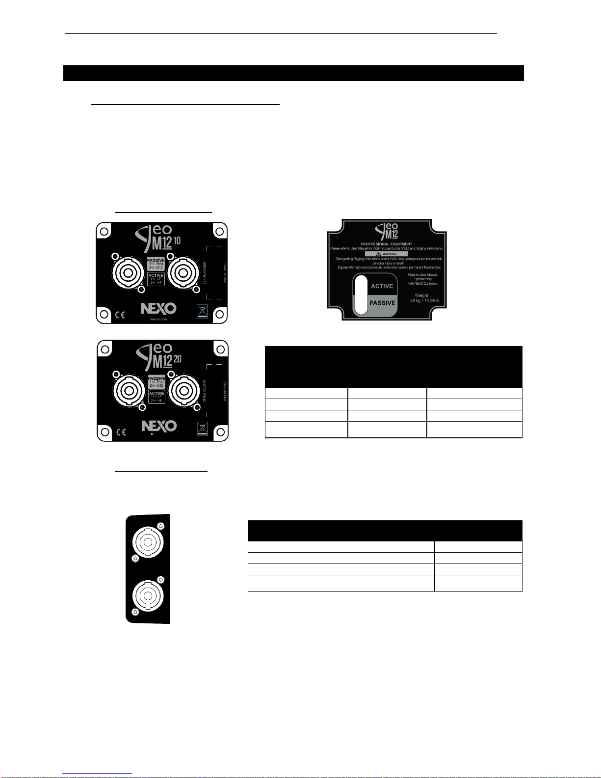
2.1.1 GEO M12 connectors
Selection of Active or Passive Mode
2.1.2 MSUB18 connectors
MSUB18 features 2 connector panels with 2 Speakon NL4 each so that cabling is always done at the
back independently of cabinet being set frontwards or rearwards for cardioid configurations.
Speakon
Connector
M1210 & M1220
Passive Mode
Active Mode
1(-)
Through
GEO M12 LF (-)
1(+)
Through
GEO M12 LF (+)
2(-)
GEO M12 (-)
GEO M12 HF (-)
2(+)
GEO M12 (+)
GEO M12 HF (+)
Speakon Connector
MSUB18
1(-)
MSUB18 (-)
1(+)
MSUB18 (+)
2(-)
Through
2(+)
Through
GEOM12 GENERAL SET-UP INSTRUCTIONS Page 9/90
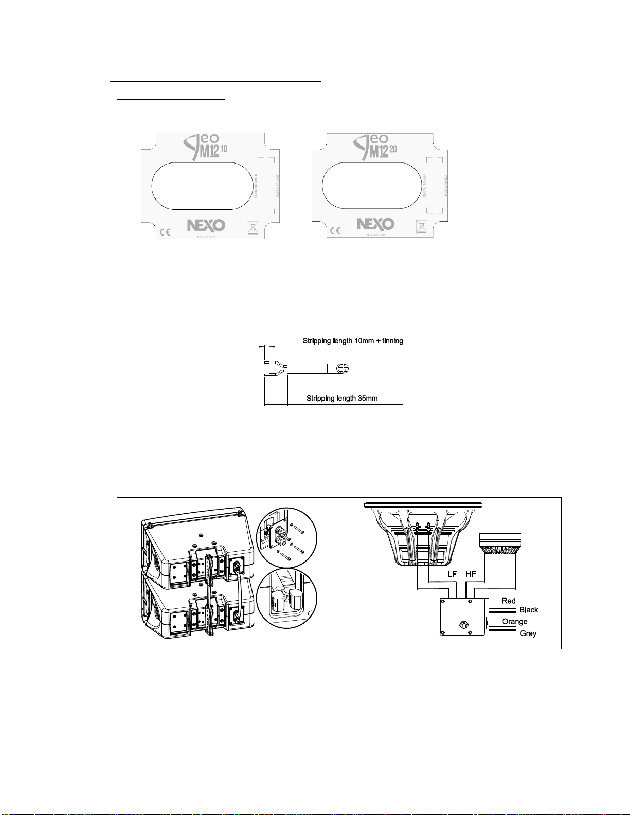
2.2 GEO M12-I and MSUB18-I connections
2.2.1 GEO M12-I connectors
GEOM12-I are connected through 2 captive cables and 2 fast connectors.
In order to connect for installation:
- Remove the connecting plate.
- Pass the cables through the cable-gland (maximum cable outside diameter is 12mm / 0.5”, maximum
gauge wire is 2.5 mm2/ AWG13 for solid cable and 4 mm2/ AWG11 for multi-stranded cable)
- Prepare cable as below
- Connect to the fast connectors (+): Brown (or Red) / (-): Blue (or Black).
- Remount the connecting plate.
- Tight the cable-gland and adjust the length.
- Seal the cabinet with the provided blind plug on the unused cable gland.
Page 10/90 GEOM12 GENERAL SET-UP INSTRUCTIONS
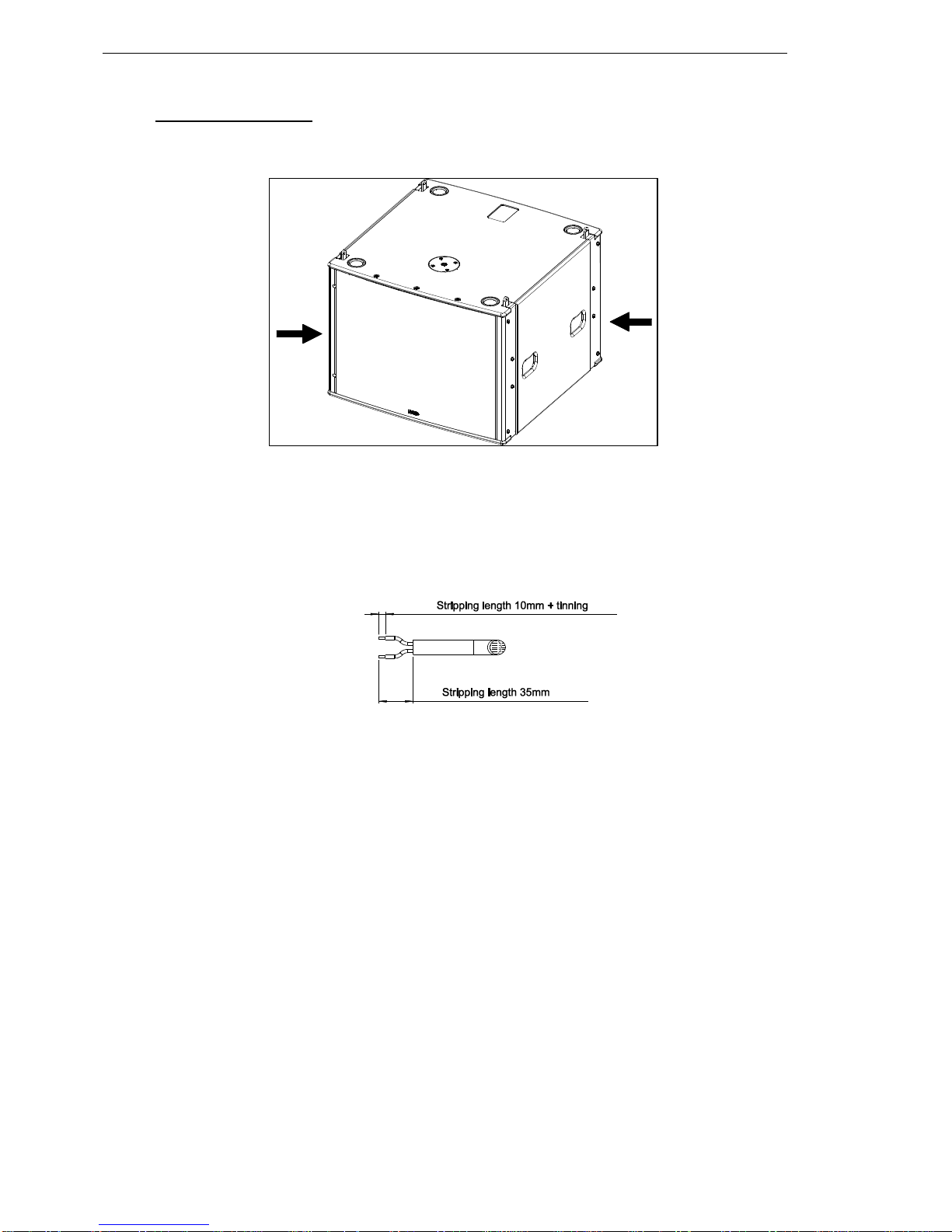
2.2.2 MSUB18-I connectors
MSUB18-I are connected through 2 fast connectors located behind the corner plates as in drawing below.
In order to connect for installation:
- Remove the corner plates.
- Pass the cables through corner plate openings (maximum cable outside diameter is 11mm / 0.4”,
maximum gauge wire is 2.5 mm2/ AWG13 for solid cable and 4 mm2/ AWG11 for multi-stranded
cable)
- Prepare cable as below
- Connect to the fast connectors (+): Brown (or Red) / (-): Blue (or Black).
- Remount the corner plate.
GEOM12 GENERAL SET-UP INSTRUCTIONS Page 11/90
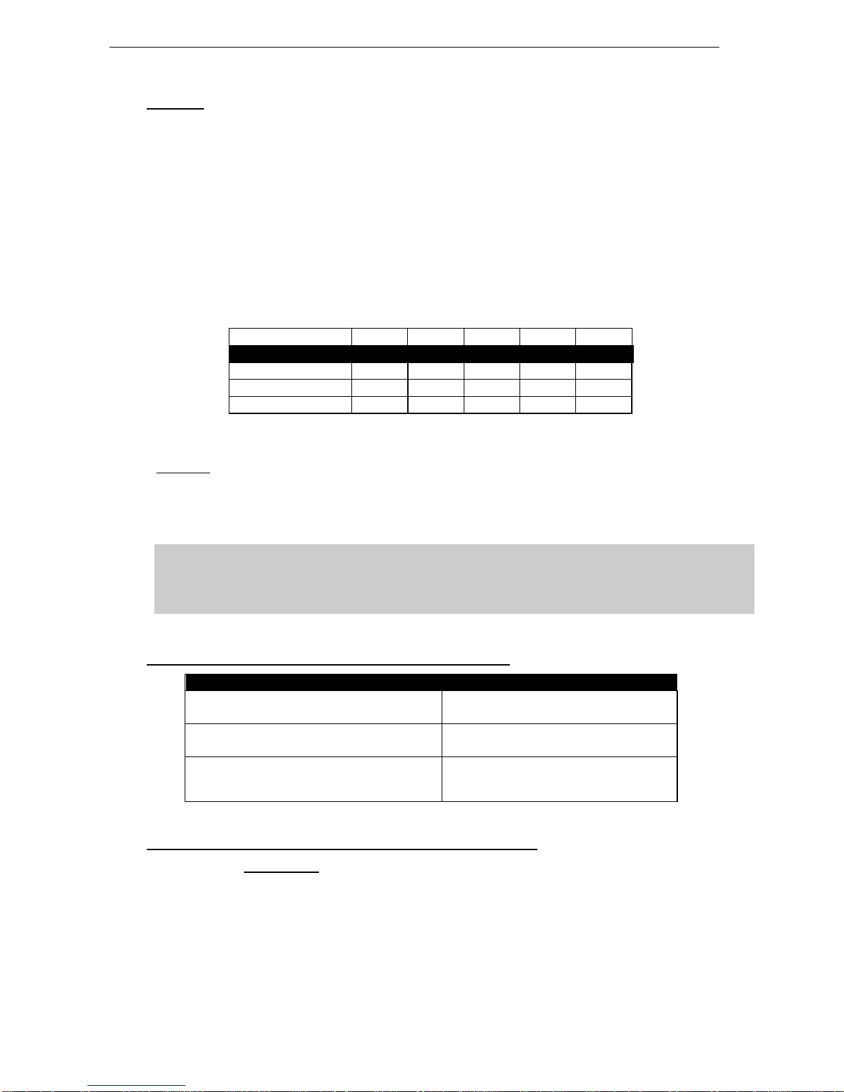
2.3 Cabling
NEXO recommends the exclusive use of multi-conductor cables to connect the system: the cable kit is
compatible with all the cabinets, and there is no possible confusion between LF, MF and HF sections.
Cable choice consists mainly of selecting cables of the correct sectional dimension (size) in relation to
the load resistance and the cable length. Too small a cable section will increase both its serial resistance
and its capacitance; this reduces the electrical power delivered to the loudspeaker and can also induce
response (damping factor) variations.
For a serial resistance less or equal to 4% of the load impedance (damping factor = 25), the recommended
cable length is given by:
Lmax = Z x S S in mm2, Z in Ohm, Lmax in meters
The table below indicates these values, for 3 common sizes.
Load Impedance ()
2
3
4
6
8
Cable section
Recommended Cable Length
1,5 mm² (AWG #14)
3m/10ft
4.5m/13ft
6m/20ft
9m/30ft
12m/39ft
2,5 mm² (AWG #12)
5m/16ft
7.5m/23ft
10m/33ft
15m/49ft
20m/66ft
4 mm² (AWG #10)
8m/26ft
12m/39ft
16m/52ft
24m/79ft
32m/105ft
Maximum allowed length is 4 times recommended length.
Example:
GEO M12 module has a 8 nominal impedance in passive mode. When connecting 4 modules in parallel,
total load impedance become 2.
Recommended length for 4mm2/ (AWG#10) is 8m / 26ft, maximum allowed length is 32m / 105ft.
IMPORTANT
Long speaker cables induce capacitive effects –up to hundreds of pF depending on the
quality of the cable - with a low-pass effect on high frequencies. If long speaker cables
must be used, ensure that they do not remain coiled while in use.
2.4 GEO M12 & MSUB18 recommended amplification
NEXO TD Controllers
Recommended amplification
NXAMP4x1mk2 Powered Controller Bridged Stereo mode
(2x2.6kW/4)
2 x GEO M12 in passive mode per bridged channel
1 x MSUB18 per bridged channel
NXAMP4x2mk2 Powered Controller 4 channels mode
(4x2.5kW/2)
1 x GEO M12 in passive mode per channel
1 x MSUB18 per channel
NXAMP4x4 Powered Controller 4 channels mode
(4x4kW/2)
3 x GEO M12 in passive mode per channel
3 x GEO M12 in active mode: 2 channels
2 x MSUB18 per channel
2.5 GEO M12 & MSUB18 setups on NEXO TD Controllers
Please consult nexo-sa.com for NEXO TD Controllers firmware information.

Page 12/90 CONNECTION DIAGRAMS
3CONNECTION DIAGRAMS
3.1 GEO M12 (passive mode) / NXAMP4x1mk2 (Bridge Stereo)
3.2 MSUB18 / NXAMP4x1mk2 (Bridge Stereo)

CONNECTION DIAGRAMS Page 13/90
3.3 GEO M12 (passive mode) and MSUB18 / NXAMP4x1mk2 (Bridge Stereo)
Page 14/90 CONNECTION DIAGRAMS
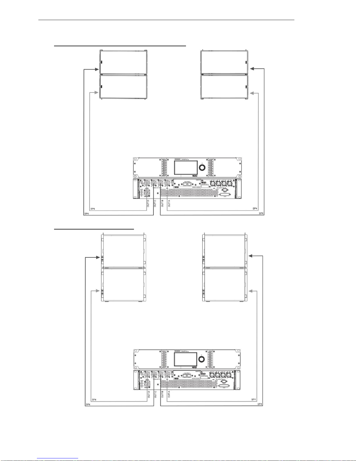
3.4 GEO M12 (passive mode) / NXAMP4x2mk2
3.5 MSUB18 / NXAMP4x2mk2
CONNECTION DIAGRAMS Page 15/90
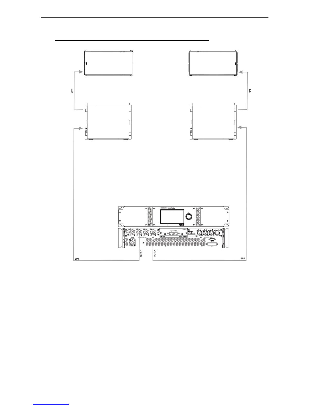
3.6 GEO M12 (passive mode) and MSUB18 / NXAMP4x2mk2
Page 16/90 CONNECTION DIAGRAMS
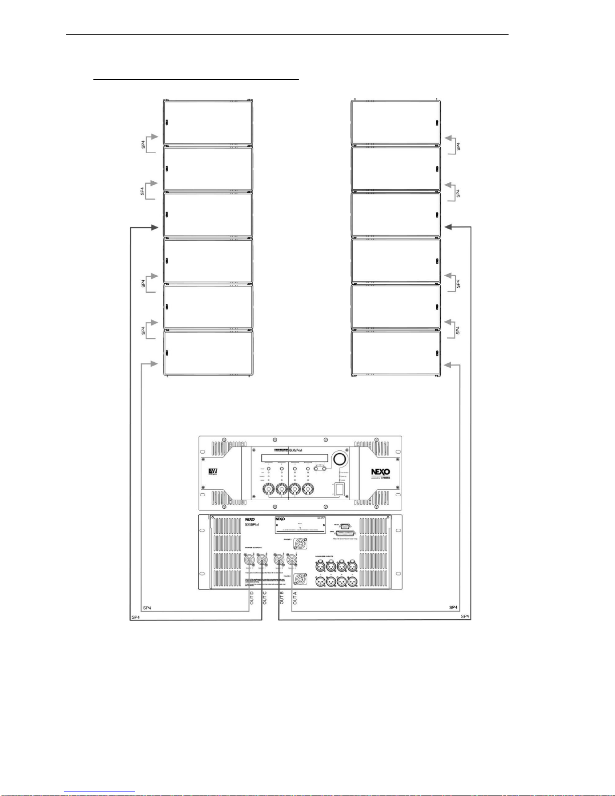
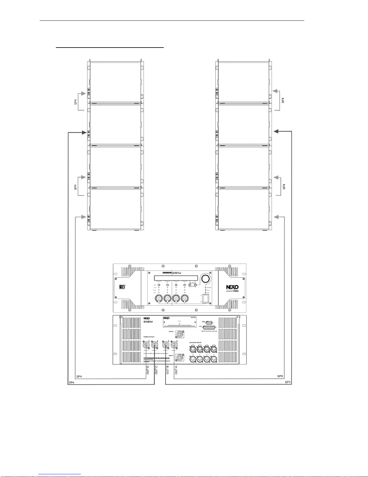
3.7 GEO M12 (passive mode) / NXAMP4x4

CONNECTION DIAGRAMS Page 17/90
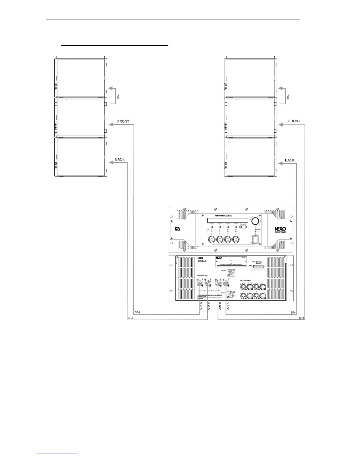
3.8 GEO M12 (active mode) / NXAMP4x4
Page 18/90 CONNECTION DIAGRAMS
3.9 MSUB18 Omni Mode / NXAMP4x4
CONNECTION DIAGRAMS Page 19/90
3.10 MSUB18 Cardio Mode / NXAMP4x4

Page 20/90 CONNECTION DIAGRAMS
3.11 GEO M12 (passive mode) and MSUB18 / NXAMP4x4
This manual suits for next models
3
Table of contents


