NextgenID BioAxs 9800IR User manual

BioAxs 9800IR™
Multi-Modal Biometric Access Panel
Fingerprint & Iris Recognition
Installation & Operations Manual
Version 1.9
P/N: NG-DOC-BA9800IR-IOM

BioAxs 9800IR™ Installation & Operations Manual. Version 1.9
THIS PAGE INTENTIONALLY LEFT BLANK
Copyright ©2004 NextgenID, Ltd. All Rights Reserved
2

BioAxs 9800IR™ Installation & Operations Manual. Version 1.9
Notices
Notice: The information in this document is subject to change without notice. Please contact
support@NextgenID.com and refer to P/N NG-DOC-BA9800IR-IOM
.
Notice: Any use of this product is subject to the terms and acceptance of the NextgenID Ltd
“Software Agreement.” You may request a copy of the “Software Agreement” from NextgenID Ltd
Notice: Windows™, Windows 2000™, Windows NT™, Windows XP™ are trademarks and/or
registered trademark of Microsoft Corporation in the United States and/or other countries.
Notice: IrisAccess™ is a registered trademark of LG Electronics Institute of Technology in the
United States and/or other countries.
Fire Safety Notice Never connect BioAxs Access Control devices or locks to doors,
gates or barriers without first consulting the local fire codes. You must consult with, and
get approval of, local fire officials before installing locks or devices on any doors that may
be fire exits. Use of request to exit push buttons may not be legal. A single action exit
mechanism may be required. Always obtain the proper permits and approvals in writing
before installing access control equipment, door locks and associated readers.
Copyright ©2004 NextgenID, Ltd. All Rights Reserved
3
Notice: The NextgenID Ltd. Logo, and the NextgenID Ltd products referred to herein are either
the trademarks or the registered trademarks of NextgenID Ltd. All other trademarks are property
of their respective owners. NextgenID Ltd. assumes no responsibility for errors that may appear
in this manual. Information contained herein is subject to change without notice.

BioAxs 9800IR™ Installation & Operations Manual. Version 1.9
Contacts
Mailing Address
NextgenID, Ltd.
10226 San Pedro
Suite 100
San Antonio, TX 78216 USA
By Phone
Phone (210) 530-9991
Fax: (210) 530-9992
Email
World Wide Web
Copyright ©2004 NextgenID, Ltd. All Rights Reserved
4
Support.NextgenID.com

BioAxs 9800IR™ Installation & Operations Manual. Version 1.9
Contents
NOTICES........................................................................................................................... 3
CONTACTS ...................................................................................................................... 4
INTRODUCTION............................................................................................................. 8
BIOAXS 9800IR™ ™ FEATURES / GENERAL SPECIFICATIONS .................... 10
CHAPTER 1: PREPARING FOR INSTALLATION................................................. 12
SITE SURVEY AND PREPARATION................................................................................... 12
Locating the BioAxs 9800IR™ Access Panel........................................................... 12
Locating the Door Commander Module (DCM) ...................................................... 13
Ethernet Connectivity (LAN)..................................................................................... 13
Power Requirements................................................................................................. 13
Earth Ground............................................................................................................ 14
Cabling Runs / Conduit Installation......................................................................... 14
Installation Tools Required....................................................................................... 14
Customer / Installer Supplied Hardware and Cabling............................................. 14
ESD Precautions....................................................................................................... 15
CHAPTER 2: UNPACKING......................................................................................... 16
Unpacking the BioAxs 9800IR™ Access Control System......................................... 16
Verify Shipping Contents .......................................................................................... 17
Optional Equipment and Accessories....................................................................... 17
CHAPTER 3: HARDWARE SPECIFICATIONS ...................................................... 18
Power Requirements................................................................................................. 18
Battery Backup.......................................................................................................... 18
Output Power............................................................................................................ 18
Earth Ground............................................................................................................ 18
Relay Output Points.................................................................................................. 19
Alarm Input Points.................................................................................................... 19
Operating Temperatures........................................................................................... 19
Operating Relative Humidity.................................................................................... 19
Dimensions................................................................................................................ 19
Weight....................................................................................................................... 19
CHAPTER 4: WIRING SPECIFICATIONS............................................................... 20
Networking................................................................................................................ 20
DCM Communications Extender (Access Panel to DCM Extender Unit)................ 20
Access Panel Video Cable ........................................................................................ 21
Iris Recognition Video Cable.................................................................................... 21
Iris Recognition Serial Communications RS422 Cable............................................ 21
24V Power Cable...................................................................................................... 22
Alarm Input points .................................................................................................... 22
Copyright ©2004 NextgenID, Ltd. All Rights Reserved
5
Relay outputs............................................................................................................. 22

BioAxs 9800IR™ Installation & Operations Manual. Version 1.9
Wiegand Signaling.................................................................................................... 22
Earth Ground............................................................................................................ 22
CHAPTER 5: WIRING OVERVIEW.......................................................................... 23
CHAPTER 6: INSTALLATION................................................................................... 25
DOOR COMMANDER MODULE INSTALLATION ............................................................... 25
Mount the Door Commander Module (DCM) Unit.................................................. 25
Mount the DCM Communications Extender Unit..................................................... 26
Install the FingerMatch™ Hardware Licensing Device.......................................... 26
Install the Uninterruptible Power Supply (UPS)...................................................... 27
DCM & DCM Communications Extender Power Connections................................ 27
Install the 24VDC Access Panel Power Supply........................................................ 27
BIOAXS 9800IR™ PANEL ENCLOSURE INSTALLATION ................................................. 27
Mounting the BioAxs 9800IR™ Access Panel Enclosure......................................... 27
WIRING INSTALLATION.................................................................................................. 29
Door Commander Module (DCM) Connections....................................................... 29
BioAxs 9800IR™ Access Panel DCB Wiring Connections...................................... 32
Powering the System................................................................................................. 38
NEXTGENID COMMAND CENTER SERVER AND CLIENT SOFTWARE............................... 39
ACTIVATING THE BIOAXS 9800IR™............................................................................. 39
CHAPTER 8: USING THE PANEL............................................................................ 40
PRE-REQUISITES FOR PANEL USE .................................................................................. 40
Hardware Installation............................................................................................... 40
Access Panel Activation............................................................................................ 40
Member Enrollment and Privilege Assignment........................................................ 40
INTRODUCTION .............................................................................................................. 40
Authentication Protocol Overview for the BioAxs 9800IR™................................... 41
STEP 1: MEMBER IDENTIFICATION................................................................................. 42
Using Personal Identification Numbers (PIN) ......................................................... 42
Panel Feedback......................................................................................................... 42
STEP 2: MEMBER VERIFICATION.................................................................................... 42
Panel Feedback......................................................................................................... 42
STEP 3: MEMBER VALIDATION ...................................................................................... 42
Member Profile Expiration....................................................................................... 42
Access Panel ‘Lockdown’ State................................................................................ 43
Panel Feedback......................................................................................................... 43
STEP 4: ACCESS VALIDATION ........................................................................................ 43
Member Access Privileges........................................................................................ 43
Guest Privileges........................................................................................................ 44
STEP 5: GUEST PROMPTS (CONDITIONAL) ..................................................................... 44
Panel Feedback......................................................................................................... 44
ACCESS PANEL MODES OF OPERATION.......................................................................... 45
IH: PIN plus Iris or Fingerprint............................................................................... 45
II: PIN plus Iris or Fingerprint with Tailgating Countermeasure ........................... 45
Copyright ©2004 NextgenID, Ltd. All Rights Reserved
6
JE: Wiegand (Proximity Card / Magnetic Swipe) plus Iris or Fingerprint.............. 46

BioAxs 9800IR™ Installation & Operations Manual. Version 1.9
JF: Wiegand (Proximity Card / Magnetic Swipe) plus Iris or Fingerprint with
Tailgating Countermeasure...................................................................................... 46
KE: Common Access Card (CAC) plus Iris or Fingerprint...................................... 46
KF: Common Access Card (CAC) plus Iris or Fingerprint with Tailgating
Countermeasure........................................................................................................ 46
Miscellaneous Configurations.................................................................................. 47
APPENDIX A: GENERAL MAINTENANCE TASKS.............................................. 48
FINGERPRINT SENSOR HARDWARE MAINTENANCE........................................................ 48
Cleaning the Sensor.................................................................................................. 48
Sensor Maintenance Warnings................................................................................. 48
FINGERPRINT SENSOR FREQUENTLY ASKED QUESTIONS ............................................... 49
APPENDIX B: BIOMETRIC RECOGNITION PERFORMANCE ......................... 50
Fingerprint Recognition Performance Issues........................................................... 50
Iris Recognition Performance Issues........................................................................ 50
NOTES............................................................................................................................. 51
Copyright ©2004 NextgenID, Ltd. All Rights Reserved
7

BioAxs 9800IR™ Installation & Operations Manual. Version 1.9
Introduction
Biometric Access Control
A computerized method used to identify people based on their unique physical characteristics
before granting access to secure facilities.
Why biometric access control is better
Today, more than ever before, it’s important to know that only authorized people are in your
secure areas. NextgenID biometric access control products provide secure, affordable access
control for all security needs.
Far superior to pin numbers or card systems, which can be shared or stolen, biometrics utilize a
person’s unique physical characteristics to identify the user. NextgenID biometric identification
and verification systems ensure that only legitimate members can enter your secure area.
NextgenID BioAxs multi-biometric hardware and software platform allows users to choose what
biometric technologies they want to deploy at each point to be secured. The BioAxs 9800IR™ is
part of the NextgenID BioAxs™ family of multi-biometric, multi-modal access control panels and
utilizes both fingerprint and iris biometrics.
Modular / Scalable
The modular, multi-biometric BioAxs solution is designed to treat each biometric component as a
verification or identification device within the scalable framework of a particular door’s security
requirements. NextgenID hardware and algorithm neutrality allow particular algorithms and
sensors to be easily integrated to meet customer requirements.
Multi-Modal Authentication Protocol
The BioAxs 9800IR™ provides multi-modal authentication modes meaning the facilities access
control administrator can adjust the access protocol necessary to obtain entry to the protected
facility. Combining traditional access control methods such as card readers, PIN Entry devices
with the latest in biometric authentication technology, the BioAxs 9800IR™ provides a robust
access control solution to a variety of threat conditions present in today’s environment.
Flexible Authentication Protocols
The BioAxs 9800IR system can be configured as an “and” system that requires both biometrics to
be verified for access to be granted. The BioAxs 9800IR™ can also be configured as an “or”
system that allows users to authenticate either their iris or their fingerprint.
Threat Level Scalability
Based on the current perceived level of threat to a given facility, the BioAxs 9800IR™ system
allows the access control administrator to configure predefined operating configurations for the
access panels. As threat conditions increase the level of the security for a facility, the panel
behavior may be ‘scaled up’ to require additional credentials for granting access. Examples of
these techniques include: combining a proximity card and biometric, adding a PIN or requiring
multiple biometrics before granting access.
Patented Dual Biometric System
Copyright ©2004 NextgenID, Ltd. All Rights Reserved
8
The BioAxs 9800IR’s patented system combines the power of two biometrics, iris and fingerprint
with the optional added security of tailgating detection to provide a formidable access control
solution for your secure facility. The system comes standard with the LG IrisAccess™
verification/identification algorithm and NextgenID FingerMatch verification/identification
algorithm.

BioAxs 9800IR™ Installation & Operations Manual. Version 1.9
FingerMatch™ fingerprint matching technology
FingerMatch™ uses both global (features that are discernible by the naked eye) and local (tiny,
unique characteristics of fingerprint ridges) feature analysis to match a fingerprint. Based on
these distinct features, fingerprints are given a unique set of numbers, which are sent to a
database to find a match. Once a match is made, the user is allowed access.
Our FingerMatch™ technology performs a fast and efficient search of large databases, making
our product the perfect solution for high traffic doors.
Stand Alone Capability
The BioAxs 9800IR™ is capable of functioning as a “stand alone” device and will open magnetic
locks or strike plates, handle request to exit buttons, and accept fire alarm shunts. The BioAxs
9800IR comes standard with an onboard proprietary door controller board and our powerful
Command Center Access Control Software. The Command Center allows for complex granting of
access privileges. Users can be granted access to a particular door during defined days and/or
hours. User Groups can be created to assign the same door privileges to a large group of users
(i.e., Lab A Technicians). All door events are accompanied by pictures and are logged for easy
searching, viewing and reporting.
Integrates with existing Access Control Systems
The BioAxs 9800IR™ can act like just another card reader on an existing access control system
and will pass card reader output to the access controller in 26-bit Wiegand data format
Weatherproof Design
The BioAxs 9800IR™ is available in a weatherproofed model that can operate in most outdoor
conditions. Down pour conditions make fingerprint authentication extremely difficult as a user not
carrying an umbrella will be unable to sufficiently wipe his or her finger semi-dry before
authenticating. Fingerprint readers cannot read prints through a significant layer of water. For
unhindered performance, BioStation™ outdoor mounting or a commercial awning will provide the
necessary “dry zone” for users to wipe the moisture from their finger. Obviously, users prefer the
amenity of an outdoor authentication spot protected from the elements. It is also available in an
XTRM Model that can operate at temperatures from -40°c to +60°c.
Flexible System Architecture
Both the hardware and software architecture of our system is designed to be extremely flexible. If
you would like to enhance an existing card swipe or proximity card system with a
BioAxs 9800IR™, we are able to accept and deliver the reader’s information in standard card
reader format via 26-bit Wiegand input and output.
Flexible Mounting Options
Copyright ©2004 NextgenID, Ltd. All Rights Reserved
9
The BioAxs 9800IR™ is available in flush or surface mount designs that utilize wall-mount, low-
voltage lighting, (indoor and outdoor available). The BioAxs 9800IR™ is also available in
NextgenID’s BioStation™ integrated lighting solution. The BioStation™ lights the user’s face from
three positions to provide a uniform, ideally lit image for recognition.

BioAxs 9800IR™ Installation & Operations Manual. Version 1.9
BioAxs 9800IR™ ™ Features / General Specifications
Iris Recognition Unit featuring
LG Iris' IrisAccess™ 3000
Onboard Panel Camera
Fingerprint Recognition
Sensor
Wiegand / Common Accces Card
Reader (Optional)
Integrated Keypad
Text Display
Speaker (hidden)
Figure 1 - BioAxs 9800IR™ Biometric Access Panel Front View
Copyright ©2004 NextgenID, Ltd. All Rights Reserved
10
Feature Specification
Fingerprint Identification Algorithm NextgenID FingerMatch™
IRIS Recognition Identification Algorithm Algorithm independent Multi Biometric Platform. The
BioAxs 9800IR™ comes standard with LG Iris’ IrisAccess™
Iris Recognition Engine
Real time network monitoring Yes
Fingerprint Enrollments per User 10 Templates (All Fingers)
Fingerprint FAR 0.001%
Fingerprint Lookup Modes Verification & Identification 1-N, 1-1, 1-Few
Fingerprint FRR (After Capture) 0.01%
Iris Equal Error Rate (EER) 1 in 1.2 million
On-The Fly Adjustable Authentication Mode Standard
Iris Recognition Lookup Modes Verification 1-1, 1-Few
Identification/ Authentication Modes (some
modes listed require optional equipment e.g.
card reader)
PIN Only
Card Only
PIN + Finger
Card + Finger
PIN + Iris
Card + Iris
PIN + [Finger or Iris]
Card + [Finger or Iris]
Card + Iris + Finger
PIN + Iris + Finger
DoD Common Access Card Configurations also available
Fingerprint Identification Time (After Image
Capture) 1 second / 30000 Templates Identification Mode
Fingerprint Verification Time (After Image
Capture) Sub-1 second

BioAxs 9800IR™ Installation & Operations Manual. Version 1.9
Rotational Tolerance Fingerprint Scan 360°
Iris Verification Time (After Image
Capture) .5–1s Verification Mode
Fingerprint Templates Unlimited 1
Iris Templates Unlimited 1
Fingerprint Template Cache 10,000 templates (Scalable)1
Event Logging Unlimited1
Event Monitoring Real Time
Networking TCP/IP (10Base-T, 10 /100Mbps)
Battery Backup Minimum 2 hours Recommended
Card Reader Wiegand Output
Lock Control Wiegand Output (26 bit) and/or Stand Alone Door Control
Capable
Tailgating Detection Yes (optional equipment)
Point of Entry Images captured with Events Yes
Door Ajar Alarm and Events Yes
Panel Tamper Alarm Yes
User Duress Notification via selectable
biometric Per fingerprint enrollment
Multi-Centric User and Panel Management /
Department Segmental Management Yes
Operating Temperature Range 0° C to +60° C Standard
-40° C to +60° with Extreme Weather Option
Visitor Enrollment (expiring enrollments) Yes
Schedule Open Access Periods Per Door Yes
Schedule Access Periods Per Group or
Individual Yes
Facility Lock Down Mode Yes
Relative Humidity 0-85% Non-condensing
Access Panel Dimensions 11.25 x 18.25 x 4.75 (285.75 x 463.55 x 120.65 mm)
Fingerprint Reader Sensor Type Optical
Sensor Size 14.6 mm (nominal width at center) x 18.1 mm (nominal
length)
Fingerprint Sensor Resolution 512 DPI
Operating System Support Microsoft Windows 2000/XP
Power 110 VAC / 220VAC, 24VDC to Access Panel
Notes: 1Actual capacity may vary depending on user selectable options
Copyright ©2004 NextgenID, Ltd. All Rights Reserved
11

BioAxs 9800IR™ Installation & Operations Manual. Version 1.9
Chapter 1: Preparing for Installation
Site Survey and Preparation
Locating the BioAxs 9800IR™ Access Panel
The BioAxs 9800IR™ Access Panel should be mounted on a wall or structure to comply with all
local and federal laws as they apply to the installation site.
Use the following guidelines when choosing a mounting location for the BioAxs 9800IR™:
• The panel is to be located at least 6 inches from the doorjamb and at least 1’ from any
adjacent wall.
• In order to ensure the highest level of performance for facial recognition, the BioAxs
9800IR™ should be mounted such that the bottom of the access panel enclosure is at a
height of 50-1/2” inches from the ground.
• Consideration should be given to the overall distance from the BioAxs 9800IR™ to the
Entry point. Select a location that will allow a user to enter the secured facility within
approximately 2 seconds of being granted access by the access control system.
• Always mount the BioAxs 9800IR™ opposite of the opening door swing direction to
prevent interference with individuals exiting the secured area.
Secure Area
Non-Secure
Area
B
3'-0"
BioAxs 9800IR
FP
IR
1'-0" 6"
Typical Mounting Areas
A
Figure 2 Typical Mounting Locations for the BioAxs 9800
Copyright ©2004 NextgenID, Ltd. All Rights Reserved
12
BioAxs 9800IR™ Installation & Operations Manual. Version 1.9
Locating the Door Commander Module (DCM)
The DCM Module is to be located at a cable distance no greater than 100 Meters (328 ft) from the
BioAxs 9800IR™ Access Panel. Typical locations for the DCM include building communications
closets, electrical rooms, etc.
Generally, the location should provide the necessary connection points for the power and LAN
requirements of the system.
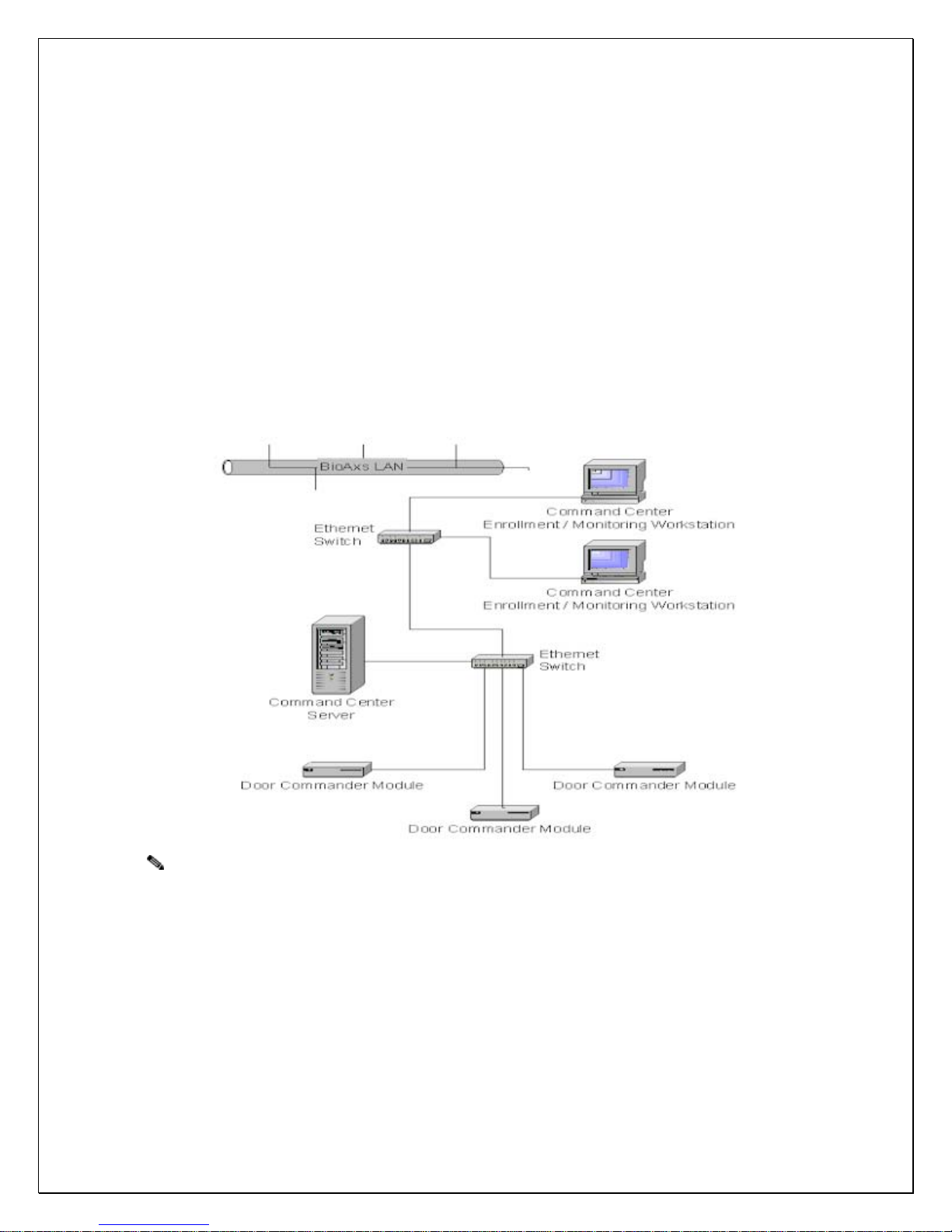
Ethernet Connectivity (LAN)
The BioAxs 9800IR™ Door Commander Module (DCM) requires a network connection to the
NextgenID Command Center™ server across a 10/100 Mb/s Ethernet network. The Command
Center Software allows centralized management and user enrollment of all BioAxs family access
control panels. For a additional information see the accompanying document, NextgenID
Command Center System Administration and User Guide P/N BA-DOC-CCSAUG. A standard
RJ45 Cat 5 Network Jack is provided on the rear panel of the DCM.
Note Always consult with your NextgenID support representative and/or the local site
Network Administrator before connecting the BioAxs 9800IR™ system to any existing
networks within a facility to ensure the proper network hardware and software security
policies have been implemented.
Power Requirements
The BioAxs 9800IR™ access panel operates at 24 VDC requiring approximately 0.33 – 2.01
amps. Consideration should be given to common ground requirements when integrating the
BioAxs 9800IR™ with existing access control systems. Select a secure location for mounting the
power supply and associated cabling. The Door Commander Module (DCM) and the DCM
Communications Extender units require 120 VAC.
Copyright ©2004 NextgenID, Ltd. All Rights Reserved
13
The power supplies should be:

BioAxs 9800IR™ Installation & Operations Manual. Version 1.9
• Isolated from other equipment
• Regulated and filtered
• Protected by means of emergency power and/or battery backup providing at least 2
hours emergency backup power
Never connect the power supply to any device or component that may put transients on
the power supply line or cause the power signal to fluctuate improperly.
See Chapter 3: Hardware Specifications for additional information
1. Amperage requirements may vary based on optional accessory and external device load.
Earth Ground
In order to protect the BioAxs 9800IR™ Access Panel device from electro-static discharge (ESD)
The access panel requires a home run connection to Earth Ground1, 2.
Warning: NextgenID may consider your warranty void if there is an improper earth ground
connection to the BioAxs 9800IR™ Access Panel
1. See Chapter 3: Hardware Specifications for specific hardware specifications
2. See Chapter 4: Wiring Specifications for details on specific cabling types
Cabling Runs / Conduit Installation
Consult local building codes and regulations when making cabling runs. The installer should
make every effort to minimize the amount of exposed conduit.
Installation Tools Required
• RJ45 Crimper
• Wire Cutters / Strippers
• Coax RCA Crimper
• Mini Screw Driver Set
• Drill and Drill Bits for mounting hardware and accessories to walls
• Carpenters Level
• Tape Measure
• Fish Tape – Pull Wire
Customer / Installer Supplied Hardware and Cabling
Below is a typical list of additional items required to install your BioAxs 9800IR™ Access Control
System. Due to the variances in local building codes and regulations, these items are to be
supplied by the customer/ installer. Please refer to the appropriate chapters in this document for
specific hardware and wiring specifications as well as recommended vendors and item part
numbers.
• Magnetic Door Sensor Switch 1
• Magnetic Door Latch Or Door Strike (Up to 1Amp @ 12V-24V DC Load)1,3
Copyright ©2004 NextgenID, Ltd. All Rights Reserved
14
• UL-Listed Class II 24V Linear Power Supply rated at 3-4 amps1. Battery backup capacity
should be sufficient for at least 2 Hours of continuous usage.

BioAxs 9800IR™ Installation & Operations Manual. Version 1.9
• Wiring and Cable, for the items listed above 2
• Wall Anchors - for use when installing wall mounted user access panel enclosure and
Door Controller Module wall mount brackets
1. See Chapter 3: Hardware Specifications for specific hardware specifications
2. See
Chapter 4: Wiring Specifications for specific details on cabling types
3. Magnetic Door Lock Devices typically require a Request-To-Exit Device. Use of request to exit
push buttons may not be legal in your area; a single action exit mechanism may be required.
Always consult local codes and regulations when installing such devices
ESD Precautions
The BioAxs 9800IR™ System contains electronics sensitive to electrostatic discharge.
Take the necessary anti-static precautions when unpacking, handling and installing all
electronic components. Do not remove the BioAxs 9800IR™ access panel from its
container until you are ready to install it
Copyright ©2004 NextgenID, Ltd. All Rights Reserved
15

BioAxs 9800IR™ Installation & Operations Manual. Version 1.9
Chapter 2: Unpacking
When you are ready to install the BioAxs 9800IR™ you should unpack, identify and account for
all items shipped with your BioAxs 9800IR™ Access Control System.
Note Do not remove the BioAxs 9800IR™ from its shipping container until you are ready to install it.
Keep the Access Panel in the shipping container until you have determined where you will install it.
Caution When handling the BioAxs 9800IR™ Access Panel without the back box, wear an ESD-
preventive strap and use an antistatic mat to avoid possible ESD damage.
Unpacking the BioAxs 9800IR™ Access Control System
To unpack the BioAxs 9800IR™ Access Control System from the shipping container, follow these steps.
Your shipment should contain at least 2 boxes. Carefully remove or cut the tape that seals each shipping
container and open the top of the outer shipping containers.
Note: shipping stabilizer material may differ from illustration.
Figure 3 Unpacking
1Accessory Box 1 4Door Commander Unit (DCM)
2Accessory Box 2 5 Foam brace / Shipping Stabilizer
3Foam brace / Shipping Stabilizer 6 BioAxs 9800IR™ Access Panel and Back Box Assembly
Copyright ©2004 NextgenID, Ltd. All Rights Reserved
16

BioAxs 9800IR™ Installation & Operations Manual. Version 1.9
Verify Shipping Contents
Check the contents of the shipping packaging and verify that the following standard items are included with
your shipment:
o BioAxs 9800IR™ Install and Operations Manual P/N: NG-DOC-BA9800IR™-IOM
o BioAxs 9800IR™ Installation and Wiring Diagram P/N: NG-DOC-BA9800IR™-IWDIAG
o Access Panel USB Extender Module P/N: NG-USBLEX-SHLD
o Access Panel DCM Communications Extender AC Adapter P/N: NG-USBLEX-AC
o Access Panel DCM Communications A-to-B USB Cable (3 ft.) P/N: NG-USBLEX-AB3
o FingerMatch HASP License Key (USB) P/N: NG-FM-HASP-USB
o ROU Serial Communications Adapter RS232 to RS 422 DB9 Adapter P/N: NG-BB422-PP9R
o Door Commander Module for IR panels (Pentium 4/ 512MB RAM) P/N: NG-DCM-IR-P4512
o Door Commander Module AC Power Cable (Pentium 4 models) P/N: NG-DCM-ACPWR-P4
o Door Commander Module Mounting Brackets (19" Rack mount) P/N: NG-DCM-BRKT-RM
o Door Commander Module Mounting Brackets (4.5" Wall mount) P/N: NG-DCM-BRKT-WM
o BioAxs 9800IR™ Access Panel (Surface Mount Indoor) P/N: BA-9800IR™-AP-SMI
OR
BioAxs 9800IR™ Access Panel (Surface Mount Outdoor) P/N: BA-9800IR™-AP-SMO
o BioAxs 9800IR™ Access Panel Enclosure (Surface Mount Indoor) P/N: BA-9800IR™-ENC-SMI
OR
BioAxs 9800IR™ Access Panel Enclosure (Surface Mount Outdoor) P/N: BA-9800IR™-ENC-SMO
Note: The BioAxs 9800IR™ Access Panel usually ships attached to the panel enclosure (back box).
Note: The Panel Keys are attached to the BioAxs 9800IR™ Front Faceplate.
If you did not receive everything you ordered, contact a NextgenID customer service
representative for assistance.
Optional Equipment and Accessories
In addition to the standard items included with the BioAxs 9800IR™, your system may be
configured with optional accessories. Verify you have received all optional equipment. If you did
not receive everything you ordered, contact a customer service representative for assistance.
Copyright ©2004 NextgenID, Ltd. All Rights Reserved
17

BioAxs 9800IR™ Installation & Operations Manual. Version 1.9
Chapter 3: Hardware Specifications
Power Requirements
Access Panel Power Supply
The BioAxs 9800IR™ access control panel requires a 24VDC linear (4 amp continuous).
NextgenID suggested manufactures and P/Ns:
Electronic Security Devices SPS-20EL
Altronix LPS5C24X Linear Power Supply/Charger LPS5C24X
Or Equivalents
Door Commander Module (DCM)
120V AC Power
DCM Communications Extender
Input 120V AC
Output DC capacity 15V DC @ 1A
Battery Backup
Access Panel Power Supply
At least 24 VDC (4amp / hr.) battery backup should be supplied or integrated with the
Access Panel 24VDC Power Supply providing 2-4 hours of full operational backup.
Note: Actual backup time is dependent on the load and age of the battery.
To maintain the maximum backup time, it is recommended that you replace the DC
power supply battery every two to four years. Test regularly according to
manufacturers instructions.
DCM Uninterruptible Power Supply (UPS)
An uninterruptible power supply device providing backup power to the DCM,
Communications Extender and Optional Network Hub should be rated for at least 750VA
/ 800W, (Input 120V Output 120V) providing at least 2-4 hours of full operational backup.
Note: To maintain the maximum backup time, test regularly and replace the UPS
batteries every two to four years.
Note: To maximize continuous operation, It is suggested that all 120 VAC
connections be tied in to the Building Emergency Power when available.
Output Power
505X/506X Door Controller Board (DCB)
12 VDC (10 to 14 volts) 500 mA for readers and accessories requiring 12 VDC
5 VDC, 500 mA output is available for readers and accessories requiring 5 VDC
Earth Ground
Access Panel Earth Ground Connection
Proper Earth Ground Requires <4 ohms resistance when measured against a
known local earth ground.
Copyright ©2004 NextgenID, Ltd. All Rights Reserved
18

BioAxs 9800IR™ Installation & Operations Manual. Version 1.9
Warning: NextgenID may consider your warranty void if there is an improper earth ground
connection to the BioAxs 9800IR™ Access Panel
Relay Output Points
• 1 double pole, double throw (DPDT) relay contact with both normally open and normally
closed sides. Rated for 5 / 12 / 24 VDC 2 amp inductive loads.
Alarm Input Points
• Enclosure tamper switch
• Door Sensor
• Alarm Shunt
• Request To Exit
Operating Temperatures
BioAxs 9800IR™ Access Panel
-0°C to +40°C
Door Commander Module
+0°C to +50°C
DCM Communications Extender
+4°C to +40°C
Operating Relative Humidity
BioAxs 9800IR™ Access Panel
0% to 85% non-condensing
Door Commander Module
0% to 85% non-condensing
Dimensions
BioAxs 9800IR™ Access Panel
11.25” x 18.25” x 4.75” (285.75mm x 463.55mm x 120.65mm)
Door Commander Module
260 mm x 240 mm x 62mm
DCM Communications Extender
100mm x 80mm
Weight
BioAxs 9800IR™ Access Panel
11 pounds, 2oz
Door Commander Module
3.0 Kg.
DCM Communications Extender
Copyright ©2004 NextgenID, Ltd. All Rights Reserved
19
0.11 lb (50g)

BioAxs 9800IR™ Installation & Operations Manual. Version 1.9
Chapter 4: Wiring Specifications
Networking
UTP Category 5 Ethernet Cable (Plenum / PVC / Riser per Application)
Suggested P/N:
• Belden 1585A Plenum UTP Cat 5e
• Belden 1583A PVC UTP Cat 5e
• Belden 1583R Riser UTP Cat 5e
• Or Equivalent
LAN Connector Pin Assignments
Straight Through Network Cable Pinouts
PIN Assignment Wire Color
1 TX+ Orange / White
2 TX - Orange
3 RX+ Green / White
4 ISOLATED GND Blue
5 ISOLATED GND Blue / White
6 RX- Green
7 ISOLATED GND Brown / White
8 ISOLATED GND Brown
Distance guidelines apply to wired networks:
Type Maximum Distance
Hub-to-Hub (100BaseTX) 5 Meters (16.4 Feet)
Hub-to-Hub (10BaseT) 100 Meters (328 Feet)
Hub-to-Switch 100 Meters (328 Feet)
Workstation to Hub or Switch 100 Meters (328 Feet)
Node-to-Node with Multi-mode Fiber Optic Cabling in Full Duplex Mode 2000 Meters (6560 Feet)
DCM Communications Extender (Access Panel to DCM Extender Unit)
UTP Category 5 Shielded Ethernet Cable (Plenum / PVC / Riser per Application)
Note: Shielded cable requires the use of shielded RJ45 Connectors Ends.
Suggested P/N:
• Belden 1624P Plenum shielded 4-pr. Cat 5
• Belden 1624R Riser shielded 4-pr. Cat 5
Copyright ©2004 NextgenID, Ltd. All Rights Reserved
20
• Or Equivalent
Table of contents
Other NextgenID Security System manuals


