Nexxt Solutions NPC-T42U61B User manual

ProfessionalSeries
Semi-knocked down
floor cabinet
NPC-T27U68B
NPC-T32U68B
NPC-T37U68B
NPC-T42U68B
NPC-T42U61B
NPC-T47U61B
NPC-T27U66B
NPC-T32U66B
NPC-T37U66B
NPC-T42U66B

Caution: this product is heavy, at least two (2) qualified people should perform the
assembly procedure. Care must also be taken while moving or positioning the
equipment.
After the cabinet has been assembled, adjust the leveling feet for greater stability.
When lowered correctly, the four leveling feet should support the full weight of the rack.
Use extreme caution when unpacking or removing the product parts from the boxes to
avoid damaging or misplacing of parts.
Do not exceed the recommended load capacity and the maximum weight supported by
the enclosure, as specified by the manufacturer’s specifications. Failure to comply will
void the warranty of this product.
Avoid rolling the cabinet on floors with uneven or rough surfaces to prevent casters
from getting stuck in gaps or otherwise being unnecessarily damaged.
When rolling the cabinet on casters, push the cabinet from the front or rear only, to
prevent the structure from tipping on its side.
Caution: use the recommended tools to avoid damaging the parts.
CABINET TIPPING HAZARD: ensure that the cabinet is properly stabilized and
steady by extending the leveling feet after it is placed in its permanent location before
any equipment is installed.
1. Introduction
Thank you for purchasing the semi-knocked down [SKD) floor cabinet from Nexxt
Solutions. Each floor unit is housed in lockable heavy-gauge metal enclosure designed to
house any rack-mounted components, such as server and storage units, modular
network or voice switches, routers, telecommunication systems and IT equipment. Its
split rear door design easily accommodates to any telecommunications room layout, by
minimizing the space required for access behind the cabinet. Our floor cabinets provide
more space for networking equipment, including the easy integration of rack PDUs and
high-density cable managers. Built to EIA rack standards with square punched mounting
holes, the equipment can be quickly attached inside the enclosure for data center or
computer room applications. Enhanced cooling capabilities are made possible by the
integration of a fan tray assembly. Product available in 600mm wide configuration, with
27, 32, 37, 42 and 47 rack spaces.
Main features
• 1764lb (800kg) maximum load capacity
• Frame construction reinforced with steel, specially made to support heavy weight
• Superior management system, with top and bottom access to cables and PDUs
• Lockable access to front and rear doors, as well as side panels
• Standard square-punched mounting rails for faster component loading
• The front door can turn 245 degrees and the rear door can be opened up to 245
degrees
• High-density mesh back doors provide outstanding ventilation to avoid overheating
• Its vertical PDU/cable management rail adds versatility for power and cable
distribution inside the enclosure
• Each unit sits on four casters, for ease of deployment and mobility
• Adjustable leveling feet for added stability
• EIA-compliant mounting rail system can be easily adjusted for equipment varying
depths
• U-rack units are numbered front and back for easy equipment integration
• Powder coat finish prevents damage caused by rust and other external factors
For support and to find out more about our complete line of products and solutions,
we invite you to visit us at nexxtsolutions.com.
User manual
Carefully read and follow the safety
instructions included in this manual before
assembling and using the cabinet.
FAILURE TO FOLLOW THESE INSTRUCTIONS CAN LEAD TO
SERIOUS INJURY, DEATH, OR DAMAGE TO YOUR EQUIPMENT
IMPORTANT SAFETY INFORMATION
ELECTRICAL
SHOCK
HAZARD.
DANGER All parts of the unit must be properly grounded to the frame
of the enclosure and connected to the Common Bonding
Network (CBN) of your facility.
1 2

Split mesh rear door with lock
Frame
Horizontal beam
Vertical rails (with rack unit markings)
Bottom tray
Side panel
Side panel stopper
2.Preliminary steps
• Prior to installing this product, you must read all instructions thoroughly.
• Keep these instructions handy in an easily accessible location for future reference.
• A clean, flat, level, and protected floor area should be provided for cabinet assembly
to prevent damage to parts.
• The installers may need to have the following items and tools available to assemble
and install the cabinet. They are not included in the box.
3. Product overview and components
Upon opening the box, make sure to inspect and account that all the items
listed below are included.
1. Phillips screwdriver
2. Power drill with the following bits: Phillips-head tip
3. Pair of gloves
4. Long nose pliers
5. Cleaning towel
6. 3mx2m mat or padded surface
1 2 3 4 5
Part ID Item Quantity Image
Front glass door with lock
Top cover with fan tray assembly
1
1
1
2
4
1
2
4
1
2
3
4
5
6
7
8
9
Rack assembly components
3 4
4 6
≥32U≤32U

10
11
13
14
15
16
17
12
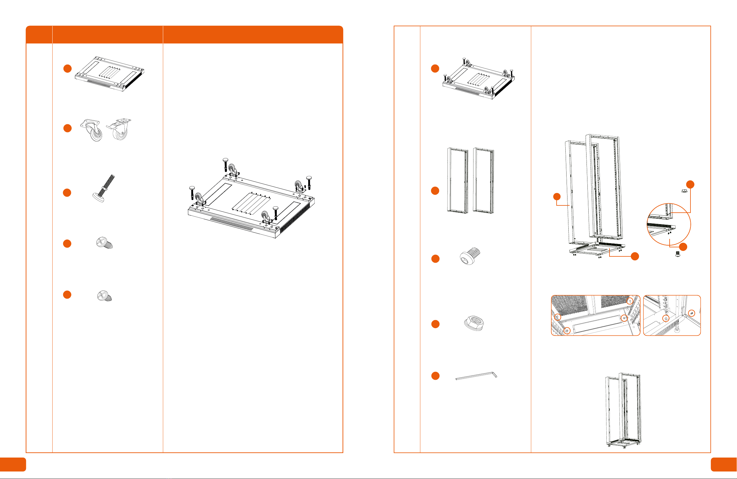
M12xL90 leveling foot
Caster wheel
Cable entry plate
Grounding cable with terminal rings
Bottom ventilation plate
Front door key
Rear door key
Side panel key
4
2 with brakes
2 without brakes
3
(1 for top and 2
for bottom panel)
3 sets
pre-installed
1 set (2 keys)
1 set (2 keys)
1 set (2 keys)
4. Assembly procedure (recommended)
Upon opening the box, inspect the contents to ensure that all the items listed above
are included:
• The illustration provides an exploded view of all the
enclosure components you are about to put together.
• Open the boxes and verify that all parts, hardware
and accessories are included in the package.
• Inspect the cabinet components and identify each
individual part to ensure proper assembly of the unit.
Rack assembly hardware ≤32U
≤27U >27 ≤37U >37 ≤47U
18
19
20
21
M6 cage nut
M6 plastic washer
M6x12mm phillps-head screw
M8x12mm hexagon socket head screw
M8 flange nut
M6x12mm self-taping screw
16
16
16
22
23
M4x8mm self-tapping screw
Door hinge bushing
L-shaped allen wrench
M6 cage nut
M6 plastic washer
M6x12mm phillips-head screw
User manual
15
3
1
Equipment mounting hardware
24
25
26
27
28
29
12
1
4
7
11 10
8
FRONT
VIEW
REAR
VIEW
4
3
5
6
5 6
≥32U
20
20
20
40
40
40
48
48
48
30
30
30
40
40
40
2
Frame installation to bottom tray
1. Align the frame (left side first) with the mounting holes on the
bottom tray. Using the M8 screws and M8 flange nuts, secure both
parts together.
Note: make sure not to fully tighten the screws until all have been
installed.
2. Repeat the same procedure for the right side.
Note: at this point, fully tighten all the screws to ensure proper
stability of the structure.
3. Make sure that the grounding post on the bottom frame aligns
with the grounding posts of the front and rear doors.
4. The bottom frame subassembly is now complete.
Bottom tray subassembly (1)
Frames (2)
M8x12mm hexagon socket
head screws (8)
M8 flange nuts (8)
7
4
21
22
1
Phase Required parts Steps
Bottom tray (1)
M6x12mm self-tapping screws (16 )
M4x8mm self-tapping screws (4)
Allen wrench
Caster wheels (4)
2 with brakes
2 without brakes
Leveling feet (4)
26
23
24
11
10
7
Installation of casters and feet
1. Identify the 2 caster wheels with brake mechanism and the 2
regular caster wheels which will be used in the back of the cabinet.
2. Align the two casters (with brakes) with the front mounting holes
of the bottom tray and secure them firmly using four (4) of the
supplied M6 self-tapping screws.
3. Repeat the same procedure for the remaining casters to be
placed in the rear section of the bottom tray.
4. Next, locate the mounting holes on each corner for the leveling
feet.
5. Screw the feet to the desired height, making sure all are
positioned at the same level.
Note: make sure not to fully extend the leveling feet to the floor until
it is placed in its permanent location. Otherwise you will not be able
to roll the cabinet using the casters.
6. Proceed to install the two cable entry plates on the tray openings
from the inside using four (4) M6 self-tapping screws.
21
22
4
7
FRONT
REAR
Front doorRear door
7 8

5. The top and bottom frame subassembly is now complete.
3
Bottom tray subassembly
M8 flanged nuts (8)
Side panel stoppers (4)
M4x8mm self-tapping screws (8)
Top cover with fan tray assembly (1)
M8x12mm hexagon socket
head screw (8)
22
24
9
21
2
Top cover assembly
1. Align the frame (left side first) with the mounting holes on the top
tray. Using the M8 screws and M8 flange nuts, secure both parts
together.
Note: position the top tray with the cable entry plates pointing
towards the rear section of cabinet.
Make sure not to fully-tighten the screws until all have been installed.
2. Repeat the same procedure for the right side of the structure.
3. Locate the mounting holes of the side panel stoppers, on the right
and left sides of the structure (front and rear), as per the illustration
below.The rubber stud should be facing outwards.
4. Attach the stoppers to the frames using the supplied M4
self-tapping screws (2 per stopper).
Note: at this time, make sure to fully tighten all the screws.
FRONT
FRONT
REAR
REAR
21
22
4
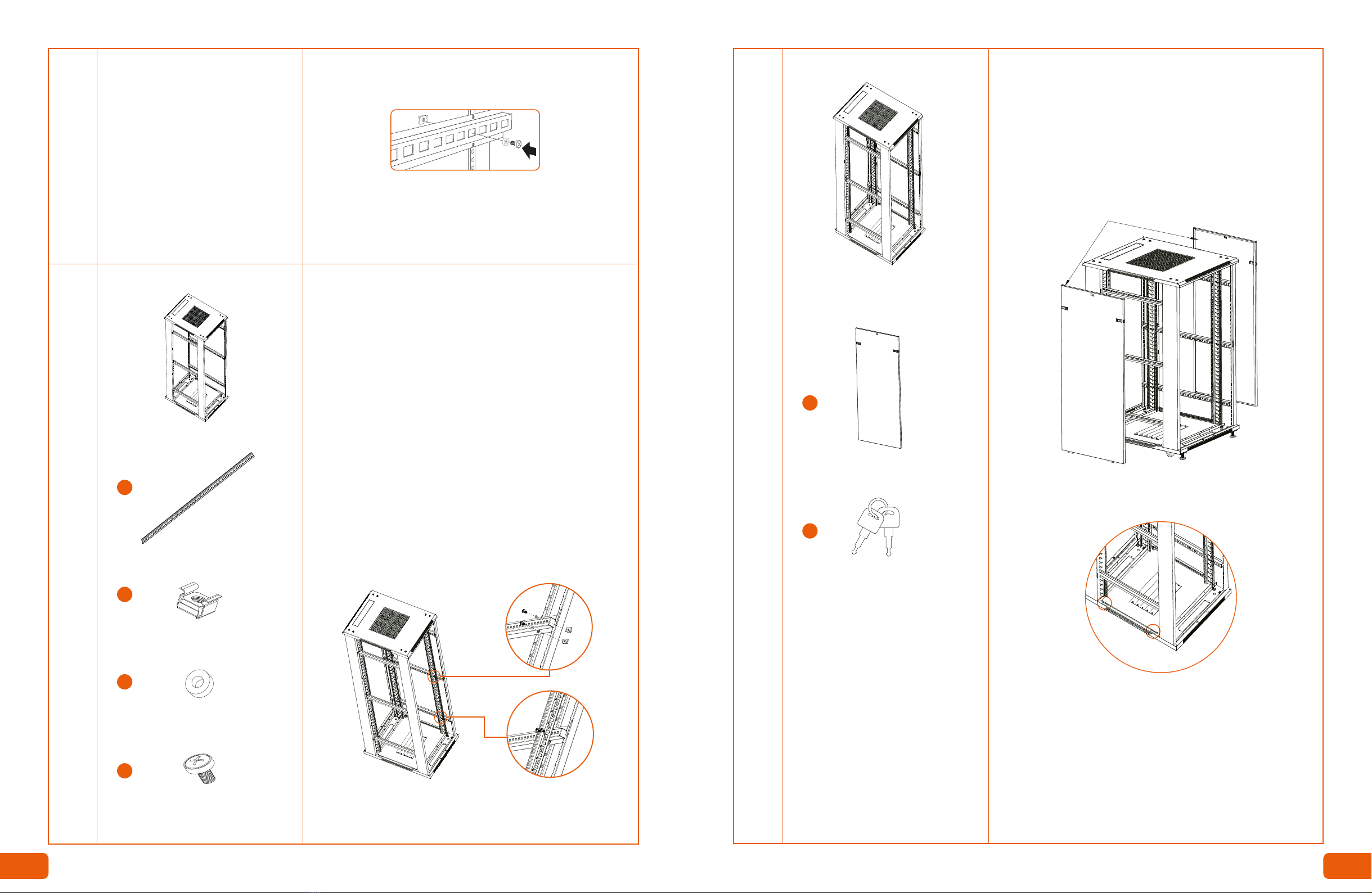
Installation of horizontal beams
1. Decide the height of the beam installation in the structure, as per
the mounting holes available in each section (top, middle and
bottom).
2. On the left frame, identify the mounting square holes, then insert
an M6 cage nut in each one, with the tabs facing outward.
Note: make sure that both ends (front and rear) of the beam are
placed at the same level.
Top and bottom frame subassembly
Top, middle and bottom beams (4 or 6)
M6x12mm phillps-head
screw (24)
5
20
M6 cage nuts (24)
M6 plastic washers (24)
18
19
9 10
Allen wrench
26
6
20
18
19
5
Vertical rails (4)
Installation of vertical rails
1. Using the structure with the beam subassembly, count up the
number of square holes on the beam from the front and rear ends
as needed, and insert two M6 cage nuts in each opening, with the
tabs facing inward.
2. Repeat this procedure until the first twelve (12) cage nuts are
installed on the left side.
3. Next, identify the 2 vertical perforated mounting rails.
4. Position the perforated mounting rails upright, so as to have the
number of rack units stamped from high (top) to low (bottom) on
each column.
Note: make sure that both ends (top and bottom) of the rail are
placed at the same level. In addition, the row of numbers on each
vertical rail must be facing each other, on the front and rear
sections of the unit.
5. Proceed to insert the M6 phillips-head screws and plastic
washers from the inside through the vertical mounting rails and into
the cage nut installed in each horizontal beam.
6. Repeat steps 1 through 5 for the right side.
Note: fully tighten the screws only after each pair of screws has
been inserted.
M6 cage nuts (24)
M6 plastic washers (24)
M6x12mm phillips screws (24)
3. Secure the assembly by inserting the M6 phillips-head screws and
washers from the inside through the horizontal beam holes and into
the cage nuts installed in the frames.
4. Repeat the same procedure for the installation on the right side.
5. After verifying that all beams are properly aligned, fully tighten all
the screws fixing the horizontal beams to the frames.
6. Now the horizontal beam subassembly is ready for the next phase.
Horizontal beam subassembly
6
3. Slide the plastic retaining latches on both sides of the panel to
their unlock position.
4. Push side panels against the support frames and release the
plastic retaining latches so as to re-engage them to their locked
position.
Note: each side panel features a pre-install key lock for securing both
sides of the enclosure. Insert the side panel key and turn it clockwise
to verify that the locking mechanism is working properly.
Installation of side panels
1. Next, identify the 2 lateral panels. Both are identical for this
model.
2. Align the tabs located on the bottom of each side panel with the
openings of the bottom tray.
Vertical rail subassembly
Side panels (2)
Side panel key set (1)
8
17
11 12

Rear door assembly
1. Identify the split rear door, bushings and pivot pins.
2. Insert the first bushing into the pivot pin at the bottom of the door
and hold it in place.
3. While supporting the door, align the bottom pivot pin with the
hinge hole on the frame, until it latches into position.
4. Next, pull down the pivot pin on the upper side of the door, align it
with the top hinge hole on the frame, and finally release it to secure
it into the enclosure.
5. Repeat the same steps to mount the other side of the door.
6. Verify that the doors are properly levelled and that both sides
open and close without friction or resistance.
7. Confirm that the door locks properly by closing the left door first,
followed by the right side door.
8. Lock the doors in position by inserting the key and turn it
clockwise to verify that the locking mechanism is working properly.
Split mesh rear door with lock (1)
Hinge bushings (2)
FRONT
REAR
7
3
25
16
Rear door key set (1)
Front door assembly
1. Identify the front door, bushing and pivot pins.
2. Insert the bushing into the pivot pin at the bottom of the door and
hold it in place.
3. While supporting the door, align the bottom pivot pin with the
hinge hole on the frame, until it latches into position.
4. Pull down the pivot pin on the upper side, align it with the top
hinge hole on the frame, and release to secure it into the enclosure.
5. Verify that the door is properly levelled and that it opens and
closes without friction or resistance.
6. Confirm that the door locks properly by pushing the handle inward,
insert the key in the lock and turn it clockwise.
7. Push the button to verify that the locking mechanism is engaged.
8. To open the door, turn the key counterclockwise and push the
button to release the handle from its locking position.
Hinge bushing (1)
Front door (1)
1
8
25
FRONT
REAR
Front panel key set (1)
15
Pivot pin Pivot pin
13 14

Equipment installation
The enclosure is now assembled and ready for equipment
installation.
1. Do not install any equipment until you have stabilized the
structure.
2. Always load the heavier items at the bottom first, followed by the
lighter equipment at the top of the enclosure, for safety reasons.
3. Identify the second and third square holes from the front (left and
right) and rear (left and right) ends and insert an M6 cage nut in
each opening, with the tabs facing inward.
4. Repeat this procedure until all M6 cage nuts are installed in the
square holes of the front and back rails.
5. Proceed to insert the M6x12mm phillips-head screws and plastic
washers from the inside through the vertical mounting rails and into
the nuts you installed in the previous step.
10
M6 cage nuts (20, 30 or 40)
M6 plastic washers (20, 30 or 40)
M6x12mm phillips-head
screws (20, 30 or 40)
29
27
28
LIGHT
HEAVY
LAST
FIRST
6. Finish by tightening the screws to secure the equipment inside
the enclosure.
Note: the square holes on the vertical rails are numbered to easily
identify each mounting point.
9
Grounding cables with terminal
rings (3 sets with copper split
and flat washers)
M4 self-tapping screw (1)
24
13
Grounding connection
1. Connect the first grounding cable to the door using the provided
hardware.
2. Likewise, connect the other end of the grounding cable to the
grounding post of the bottom tray using the hardware provided.
3.Next, connect the second grounding cable to the grounding post of
the rear door on the left side.
4. Then connect the other end of the grounding cable to the
grounding post of the bottom tray.
5. Repeat the same step for the door of the right side.
Note: fully-tighten the screws only after all the screws have been
inserted.
15 16

19 20
NotesNotes

This manual suits for next models
9
Table of contents


