NF Wave Factory WF1947 User manual

NF Corporation
MULTIFUNCTION GENERATOR
WF1947/WF1948
Instruction Manual (Operations)


MULTIFUNCTION GENERATOR
WF1947/WF1948
Instruction Manual (Operations)
DA00037851-002


WF1947/WF1948
i
——— Preface ———
Thank you very much for purchasing our "Multifunction Generator
WF1947/WF1948".
To ensure safe and proper use of this electric equipment, please read first "Safety
Precautions" on the following pages.
Caution symbols used in this manual
The following caution symbols are used in this manual. Be sure to observe these caution symbols
and their contents to ensure the safety of the user and avoid damage to the equipment.
This symbol indicates information for the avoidance of a hazard that may
endanger human life or cause injury during handling of the equipment.
This symbol indicates information for the avoidance of personal injury or
equipment damage during handling of the equipment.
This manual has the following chapter organization.
The instructions for the external control (GPIB, USB) are provided in a separate manual
included in the attached CD-ROM.
If using this equipment for the first time, start with "1. Outline."
Operations
1. Outline
This chapter describes the overview and brief operating principles of this product.
2. Preparations before Use
This chapter describes important preparations before installation and operation.
3. Panels and I/O Terminals
This chapter describes the functions and operations of the switches and I/O terminals on the panels.
4. Basic Operation
This chapter describes basic operations.
5. Saving and Recalling Settings
This chapter describes how to save and recall the settings.
6. Creating Arbitrary Waveforms
This chapter describes how to input and edit arbitrary waveforms from the panel control.
7. Convenient Use of 2-channel Equipment (WF1948 Only)
This chapter describes how to coordinate the settings of two channels.
CAUTION
WARNING

WF1947/WF1948
ii
8. Synchronizing Multiple Units
This chapter describes how to configure a multi-phase oscillator by connecting multiple units of
this product.
9. Using External Frequency Reference
This chapter describes how to use external frequency reference.
10. Using User-defined Units
This chapter describes the units which users can define by themselves.
11. Other Utility Settings
This chapter describes how to set display and operational details.
12. Troubleshooting
This chapter describes the error messages and handlings when problems occur.
13. Maintenance
This chapter describes how to perform the operation inspection and performance test.
14. List of Initial Settings
This chapter describes the initial settings.
15. Specifications
This chapter describes the product's specifications (functions and performance).

WF1947/WF1948
iii
——— Safety Precautions ———
To ensure safe use, be sure to observe the following warnings and cautions.
NF Corporation shall not be held liable for damages that arise from a failure to observe these
warnings and cautions.
This product is a Class I equipment (with protective conductor terminal) that conforms to the JIS
and IEC insulation standards.
Be sure to observe the contents of instruction manual.
This instruction manual contains instructions for safe operation and use of this product.
Be sure to read this manual first before using this product.
All the warnings in this instruction manual are intended to prevent hazards that may lead to
serious accidents. Be sure to observe them.
Be sure to ground the product.
This product uses a line filter, which may cause electric shock if the product is not grounded.
This product is grounded automatically by connecting a three-pin power supply plug to a power
supply outlet with a protective earth contact.
Check the power supply voltage.
This product operates on the power supply voltage indicated in "2.3 Grounding and Power
Connections" in this instruction manual.
Prior to connecting the power supply, check that the outlet voltage matches the rated power
voltage of the product.
In case of suspected anomaly
If this product emits smoke, an abnormal smell, or abnormal noise, immediately power it off and
stop using it.
If such an abnormal occurs, prevent anyone from using this product until it has been repaired,
and immediately report the problem to NF Corporation or one of our representatives.
Do not use this product when gas is present.
An explosion or other such hazard may result.
Never remove the cover.
This product has high-voltage portions inside. Absolutely never remove its cover.
Even when the inside of this product needs to be inspected, do not touch the inside. All such
inspections are to be performed by service technicians designated by NF Corporation.

WF1947/WF1948
iv
Do not modify the product.
Absolutely never modify this product, as this may cause new hazards and may disqualify this
product from repair in case of failure.
Safety-related symbols
The general definitions of the safety-related symbols used on this product are provided below.
Instructions Manual Reference Symbol
This symbol is displayed to alert the user to potential danger and refer him/her to the
instruction manual.
Electric Shock Danger Symbol
This symbol indicates locations that present a risk of electric shock under specific
conditions.
The general definitions of the safety-related symbols used in the instruction manual are provided
below.
Warning Symbol
This symbol indicates information for the avoidance of a hazard such as electric shock that
may endanger human life or cause injury during handling of the equipment.
Caution Symbol
This symbol indicates information for the avoidance of damage to the equipment during
handling.
Other symbols
This mark indicates that the outer conductor of the connector is connected to the
enclosure.
This mark indicates that the outer conductor of the connector is insulated from the
enclosure.
It indicates, however, that the potential difference from the grounding potential is
restricted to 42Vpk or lower for safety (Since this product is grounded when being
used, the potential of the enclosure equals the grounding potential).
Request about disposal
To protect the environment, ensure that this device is disposed of by an appropriate industrial
waste processor. A battery is not used for this product.
WARNING
CAUTION

WF1947/WF1948
v
Table of Contents
Page
1. Outline ............................................................................................................................. 1-1
1.1 Features ....................................................................................................................1-2
1.2 Operating Principles ................................................................................................ 1-3
2. Preparations before Use.................................................................................................. 2-1
2.1 Checking Before Use ................................................................................................ 2-2
2.2 Installation ...............................................................................................................2-4
2.3 Grounding and Power Supply Connection .............................................................. 2-5
2.4 Calibration................................................................................................................ 2-6
3. Panels and I/O Terminals ...............................................................................................3-1
3.1 Panel Component Names and Functions ................................................................ 3-2
3.1.1 Front Panel of WF1947................................................................................. 3-2
3.1.2 Rear Panel of WF1947 .................................................................................. 3-3
3.1.3 Front Panel of WF1948 ................................................................................. 3-4
3.1.4 Rear Panel of WF1948 .................................................................................. 3-5
3.2 I/O Terminals ........................................................................................................... 3-6
3.2.1 Waveform Output (FCTN OUT) ...................................................................3-7
3.2.2 Synchronization/Sub-output (SYNC/SUB OUT) .........................................3-8
3.2.3 External Modulation/Addition Input (MOD/ADD IN) ................................ 3-9
3.2.4 External Trigger Input (TRIG IN) .............................................................3-10
3.2.5 External 10 MHz Frequency Reference Input (10 MHz REF IN) ............ 3-11
3.2.6 Frequency Reference Output (REF OUT).................................................. 3-12
3.3 Cautions on Floating Ground Connection ............................................................ 3-13
4. Basic Operation ............................................................................................................... 4-1
4.1 Power On/Off and Restoration of Settings .............................................................. 4-2
4.1.1 How to Turn Power On/Off ........................................................................... 4-2
4.1.2 Restoration of Settings at Power-on ............................................................ 4-3
4.2 Screen Configuration and Operation ......................................................................4-6
4.2.1 Screen Configuration .................................................................................... 4-6
4.2.2 Switching Display Format with Tabs (To Display Waveform Graph) ....... 4-8
4.2.3 Top Menu .....................................................................................................4-10
4.3 Basic Settings and Operations .............................................................................. 4-11
4.3.1 To Change Frequency, Amplitude, and Other Values .............................. 4-11
4.3.2 To Change Waveforms ................................................................................4-13
4.3.3 Shortcut Keys for Changing Basic Parameters......................................... 4-14
4.3.4 Functions of ENTER/CANCEL/UNDO Key...............................................4-15
4.3.5 To Change Display Unit .............................................................................4-16
4.3.6 CH1/CH2 Switching Key and Active Channel (WF1948 Only) ................ 4-18

WF1947/WF1948
vi
4.3.7 Operations Available on Utility Screen ..................................................... 4-19
4.3.8 To Restore Initial Settings ......................................................................... 4-21
4.3.9 Output On/Off Operation............................................................................ 4-21
4.4 Setting Methods for Main Items............................................................................ 4-23
4.4.1 Configuration of Text Display Screen in Continuous Oscillation Mode .. 4-23
4.4.2 To Set Oscillation Mode .............................................................................. 4-23
4.4.3 To Set Waveforms ....................................................................................... 4-24
4.4.4 To Set Frequency ........................................................................................4-24
4.4.5 To Set Period ............................................................................................... 4-25
4.4.6 To Set Phase ................................................................................................ 4-25
4.4.7 To Set Amplitude ........................................................................................ 4-28
4.4.8 To Set DC Offset.......................................................................................... 4-30
4.4.9 To Set Output Level with High/Low Level ................................................ 4-31
4.4.10 To Set Waveform Polarity and Amplitude Range ..................................... 4-32
4.4.11 How to Use Auto Range/Range Hold for Output Voltage ......................... 4-34
4.4.12 To Set Load Impedance...............................................................................4-35
4.4.13 To Add External Signal .............................................................................. 4-36
4.4.14 To Set Duty of Square Wave....................................................................... 4-38
4.4.15 To Set Pulse Width and Leading/Trailing Time of Pulse Wave ............... 4-40
4.4.16 To Set Ramp Wave Symmetry.................................................................... 4-43
4.4.17 To Inhibit Synchronization Output Signal (in Continuous Oscillation Mode
and Sine Wave is Selected) ...........................................................................................4-43
4.5 Using Arbitrary Waveforms ..................................................................................4-44
4.6 Setting and Operation of Modulation....................................................................4-45
4.6.1 Modulation Types........................................................................................ 4-45
4.6.2 Screen for Setting and Operation of Modulation ......................................4-46
4.6.3 Common Setting and Operation of Modulation.........................................4-48
4.6.4 Setting FM...................................................................................................4-51
4.6.5 Setting FSK ................................................................................................. 4-52
4.6.6 Setting PM...................................................................................................4-53
4.6.7 Setting PSK ................................................................................................. 4-54
4.6.8 Setting AM...................................................................................................4-55
4.6.9 Setting AM (DSB-SC) ................................................................................. 4-57
4.6.10 Setting DC Offset Modulation .................................................................... 4-59
4.6.11 Setting PWM ............................................................................................... 4-60
4.7 Setting and Operation of Sweep ............................................................................ 4-61
4.7.1 Sweep Types ................................................................................................ 4-61
4.7.2 Screen for Setting and Operation of Sweep ...............................................4-61
4.7.3 Common Setting and Operation of Sweep .................................................4-64
4.7.4 Setting Frequency Sweep ........................................................................... 4-73
4.7.5 Setting Phase Sweep ...................................................................................4-75
4.7.6 Setting Amplitude Sweep ........................................................................... 4-77

WF1947/WF1948
vii
4.7.7 Setting DC Offset Sweep ............................................................................ 4-79
4.7.8 Setting Duty Sweep..................................................................................... 4-81
4.8 Setting and Operation of Burst ............................................................................. 4-83
4.8.1 Burst Oscillation Types .............................................................................. 4-83
4.8.2 Auto Burst ................................................................................................... 4-84
4.8.3 Trigger burst ............................................................................................... 4-87
4.8.4 Gate Oscillation...........................................................................................4-92
4.8.5 Triggered Gate Oscillation .........................................................................4-97
5. Saving and Recalling Settings........................................................................................ 5-1
5.1 Procedure to Save Settings ......................................................................................5-2
5.2 Procedure to Recall Settings....................................................................................5-3
5.3 Restoring Saved Contents to Initial Settings .........................................................5-4
5.4 Changing Setting Memory Name ............................................................................ 5-4
6. Creating Arbitrary Waveforms ..................................................................................... 6-1
6.1 Basics ........................................................................................................................ 6-2
6.2 Display Procedure and Overview of Screen for Creating/Editing Arbitrary
Waveforms........................................................................................................................... 6-4
6.3 Creating New Arbitrary Waveform ......................................................................... 6-6
6.4 Simple Arbitrary Waveform Creating Example .....................................................6-7
6.5 Outputting Created Arbitrary Waveform ...............................................................6-8
6.6Saving Created Arbitrary Waveform ...................................................................... 6-8
6.7 Identifying Memory Space Required for Saving Arbitrary Waveforms ................6-9
7.
Convenient Use of 2-channel Equipment (WF1948 Only)
...........................................................7-1
7.1 Overview ................................................................................................................... 7-2
7.2 Copying Setting between Channels.........................................................................7-3
7.3 Unifying Settings of 2 Channels.............................................................................. 7-5
7.4 Phase Synchronization between Channels ............................................................. 7-6
7.5 Maintaining Both Channels to Same Frequency (2-Channel Coordination,
2-Phase)............................................................................................................................... 7-7
7.6 Keeping Frequency Difference Constant (2-Channel Coordination, 2-Tone) ....... 7-9
7.7 Keeping Frequency Ratio Constant (2-Channel Coordination, Ratio) ................ 7-11
7.8 Obtaining Differential Output (2-Channel Coordination, Differential).............. 7-13
8. Synchronizing Multiple Units ........................................................................................ 8-1
8.1 Connection Procedure .............................................................................................. 8-2
8.2 Performing Synchronization .................................................................................... 8-4
9. Using External Frequency Reference ............................................................................ 9-1
9.1 Purpose of Using External Frequency Reference ...................................................9-2
9.2 Connection and Usage Procedure of External Frequency Reference ....................9-2
10. Using User-defined Units.......................................................................................... 10-1
10.1 About User-defined Unit........................................................................................ 10-2
10.2 Display and Setting in User-defined Unit ............................................................10-2
10.3 Defining User-defined Units.................................................................................. 10-3

WF1947/WF1948
viii
11. Other Utility Settings................................................................................................ 11-1
11.1 Selecting Remote Interface [Remote] .................................................................... 11-2
11.2 Display Setting [Display] ....................................................................................... 11-2
11.3 Modify Knob and Modify Direction Setting [Modify Direction]........................... 11-2
11.4 Operation Sound Setting [Sound] ......................................................................... 11-3
11.5 Self Diagnosis [Self Check] .................................................................................... 11-3
11.6 Product Information Display [Information].......................................................... 11-3
12. Troubleshooting .........................................................................................................12-1
12.1 Error Messages at Power-on.................................................................................. 12-2
12.2 Error Messages during Operation .........................................................................12-3
12.3 Conflict Messages for Modulation ......................................................................... 12-7
12.4 Conflict Message for Sweep ................................................................................... 12-8
12.5 Conflict Message for Burst .................................................................................... 12-9
12.6 Suspected Failure................................................................................................. 12-10
13. Maintenance............................................................................................................... 13-1
13.1 Overview .................................................................................................................13-2
13.2 Operation Inspection.............................................................................................. 13-4
13.3 Performance Test ...................................................................................................13-5
13.3.1 Frequency Accuracy Test............................................................................ 13-5
13.3.2 Sine Wave Amplitude Accuracy Test .........................................................13-6
13.3.3 DC Offset Accuracy Test ............................................................................. 13-6
13.3.4 Sine Wave Amplitude/Frequency Characteristics Test ............................13-7
13.3.5 Sine Wave Total Harmonic Distortion Test...............................................13-8
13.3.6 Sine Wave Harmonic Spurious Test ..........................................................13-8
13.3.7 Sine Wave Non-harmonic Spurious Test ...................................................13-9
13.3.8 Square Wave Duty Accuracy Test .............................................................. 13-9
13.3.9 Square Wave Leading/Trailingg Time Test............................................. 13-10
13.3.10 Time Difference Between Channels for 2-Phase (WF1948 Only)........... 13-10
14. List of Initial Settings ............................................................................................... 14-1
15. Specifications ............................................................................................................. 15-1
15.1 Oscillation mode ..................................................................................................... 15-2
15.2 Waveform ................................................................................................................ 15-2
15.2.1 Standard Waveform .................................................................................... 15-2
15.2.2 Arbitrary Waveform ....................................................................................15-2
15.3 Frequency, phase....................................................................................................15-3
15.4 Output Characteristics .......................................................................................... 15-3
15.4.1 Amplitude .................................................................................................... 15-3
15.4.2 DC Offset ..................................................................................................... 15-4
15.4.3 Load Impedance Setting ............................................................................. 15-4
15.4.4 Waveform Output........................................................................................ 15-4
15.4.5 Synchronization/Sub-output....................................................................... 15-4
15.5 Signal Characteristics............................................................................................ 15-5

WF1947/WF1948
ix
15.5.1 Sine Wave .................................................................................................... 15-5
15.5.2 Rectangular Wave ....................................................................................... 15-5
15.5.3 Pulse Wave .................................................................................................. 15-6
15.5.4 Ramp Wave.................................................................................................. 15-7
15.6 Modulated Oscillation Mode ..................................................................................15-7
15.6.1 General ........................................................................................................ 15-7
15.6.2 FM................................................................................................................15-8
15.6.3 FSK ..............................................................................................................15-8
15.6.4 PM................................................................................................................15-9
15.6.5 PSK ..............................................................................................................15-9
15.6.6 AM................................................................................................................15-9
15.6.7 DC Offset Modulation .................................................................................15-9
15.6.8 PWM ............................................................................................................15-9
15.7 Sweep Oscillation Mode ....................................................................................... 15-10
15.7.1 General ...................................................................................................... 15-10
15.7.2 Frequency Sweep ...................................................................................... 15-11
15.7.3 Phase Sweep .............................................................................................. 15-11
15.7.4 Amplitude Sweep ......................................................................................15-12
15.7.5 DC Offset Sweep........................................................................................ 15-12
15.7.6 Duty Sweep................................................................................................ 15-12
15.8 Burst oscillation mode ......................................................................................... 15-12
15.9 Triggers.................................................................................................................15-14
15.10 Other I/Os .............................................................................................................15-14
15.11 2-Channel Coordination (WF1948 Only) ............................................................ 15-16
15.12 Synchronization of Multiple Units ...................................................................... 15-17
15.13 User-defined unit ................................................................................................. 15-18
15.14 Other Functions ................................................................................................... 15-18
15.15 General Characteristics ....................................................................................... 15-19
Outline dimensional drawing (WF1947)..............................................................15-21
Outline dimensional drawing (WF1948)..............................................................15-22
Inch rack mount dimensional drawing (for 1unit) ............................................. 15-23
Inch rack mount dimensional drawing (for 2units) ........................................... 15-24
Millimeter rack mount dimensional drawing (for 1unit)................................... 15-25
Millimeter rack mount dimensional drawing (for 2units) ................................. 15-26

WF1947/WF1948
x
Attached Figures and Tables
Page
Figure 1-1 WF1947 Block Diagram..............................................................................................1-3
Figure 1-2 WF1948 Block Diagram..............................................................................................1-4
Figure 3-1 Front Panel of WF1947 ...............................................................................................3-2
Figure 3-2 Rear Panel of WF1947 ................................................................................................3-3
Figure 3-3 Front Panel of WF1948 ...............................................................................................3-4
Figure 3-4 Rear Panel of WF1948 ................................................................................................3-5
Figure 3-5 Cautions on Floating Ground Connection for WF1947 ............................................. 3-14
Figure 3-6 Cautions on Floating Ground Connection for WF1948 ............................................. 3-14
Table 3-1 Signals Selectable for Synchronization/Sub-output ......................................................3-8

WF1947/WF1948
1-1
1. Outline
1.1 Features ....................................................................................................................1-2
1.2 Operating Principles ................................................................................................ 1-3

1.1 Features
WF1947/WF1948
1-2
1.1 Features
NF's WAVE FACTORY, "Multifunction Generator WF1947" and "Multifunction Generator
WF1948" are multifunctional oscillators based on DDS (Direct Digital Synthesizer).
WF1947 is a 1-channel device, while WF1948 is a 2-channel device.
•Highest frequency: 30MHz (sine wave), 20MHz (square wave, pulse)
•Frequency accuracy: ±(3ppm + 2pHz), high resolution of 0.01μHz. 10MHz external frequency
reference can be used
•Maximum output voltage: 20Vp-p/open, 10Vp-p/50Ω
•Large number of standard waveforms: Sine wave, square wave (variable duty), pulse (variable
pulse width/duty, Leading time, Trailing time), ramp wave (variable symmetry), and so on
•Large-capacity arbitrary waveform memory: Maximum 512 K words, saving capacity: 128
waveforms/4 M words
•Phase and waveform remain continuous even when frequency is changed or during frequency
sweep.
•Square wave and pulse with variable duty and high resolution of 0.0001%
•Pulse with variable Leading/Trailing time
•Various oscillation modes
• Continuous oscillation
• Modulation: FM, FSK, PM, PSK, AM, DC offset modulation, PWM
• Sweep: Frequency, phase, amplitude, DC offset, and duty
• Burst oscillation: Auto burst, trigger burst, gate oscillation, triggered gate oscillation
•Intuitive user interface through use of high-resolution QVGA TFT color LCD
•Two-channel coordination function with 2 phases, constant frequency difference, constant
frequency ratio, and differential output (WF1948 only)
•Floated from enclosure for each channel to reduce the effect of ground loop
•Multiple-phase oscillator can be configured by synchronizing multiple units
•USB and GPIB interfaces provided

1.2 Operating Principles
WF1947/WF1948
1-3
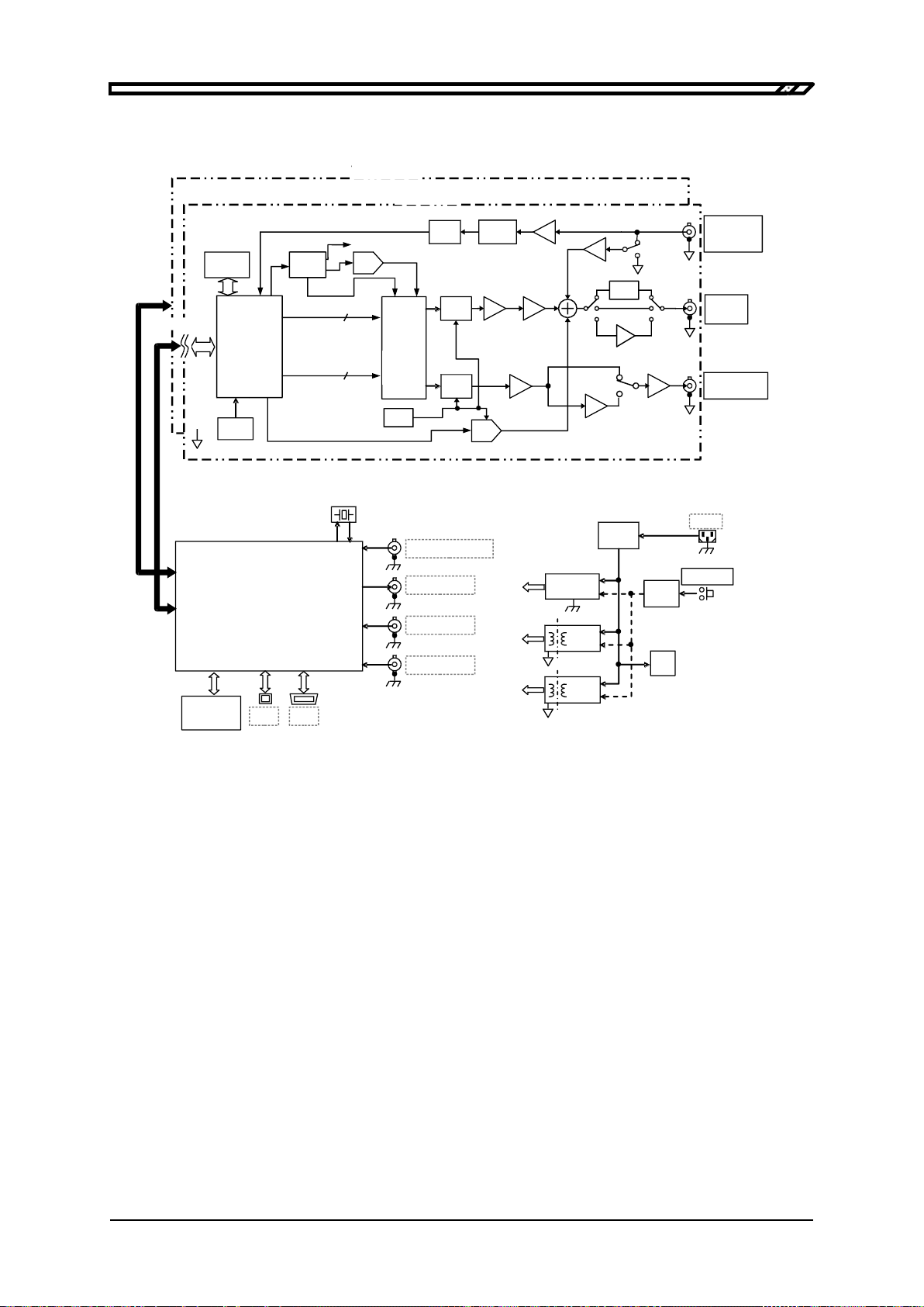
1.2 Operating Principles
■WF1947 block diagram
10MHz REF IN
REF OUT
GPIB
USB
2.5ppm VC
-TCXO
TRIG IN
20MHz
SYSTEM
CONTROLLER
(CPU, ROM, RAM,
REMOTE I/F,
MISC LOGIC)
FRONT
PANEL
UNI
T
~LINE
AC/DC
for LOGIC
(シャーシ電位)
DC/DC
FAN
POWER
PWR
CNTL
EN
DC/DC
for ANALOG
+12V
MOD/ADD
IN
FCTN
OUT
SYNC/SUB
OUT
A/D
LPF
PWR AMP
LPF
PG AMP
COMPARATOR
16bit
-
2ch
D/A
×
4
オーバ
サンプリング
D/A
OFFSET
VCO,
PLL
50kHz Bessel
5
12Kw
SSRAM
波形メモリ
8Mbit
±
10V
10MHz BW
0/
-
20dB
PG AMP
0/
-
10dB
LPF
±
1V
100
~
230V
ATT
MAIN
ANALOG
DDS
FPGA
CPLD D/A
Vref
Ref
16
16
CONT
ANALOGCONT.
アイソレーション
約230kS/s
外部変調/
外部加算/
切換え
波形同期/変調同期/
バースト同期/
スイープ同期/
スイーフXドライブ
切換え
TTL/±3V
Figure 1-1 WF1947 Block Diagram
Analog block
• The DDS (direct digital synthesizer) operates at 120 MHz clock and generates various types of
oscillation and waveform. The modulation, sweep, and burst are also processed within the DDS
FPGA.
• The digital waveform generated by the DDS are controlled by the specified polarity (normal,
inversed) and the amplitude range (-FS/0, ±FS, 0/+FS). After digital amplitude adjustment, its
signal is input into the D/A converter.
• Also, in the D/A converter, analog amplitude control is performed, and the waveform converted
into analog signal is smoothed by the LPF (lowpass filter).
• The amplitude is controlled in 10 dB steps by the PG AMP (programmable gain amplifier).
• The external addition signal and DC offset are added to the PG AMP output. If the required
output voltage is ±400mV/open or less, output is done via x1/5 ATT. If the required output
voltage exceeds ±2V/open, then output is done via x5 amplifier.
• The maximum output voltage of the product is either 20 Vp-p, 4 Vp-p, or 800 mVp-p, depending
on whether the x1/5 ATT or x5 amplifier is used. In conjunction with this, the external addition
gain is either x10, x2, or x0.4.
•The external modulation signal is passed through the LPF, converted by the A/D converter, and
then input into the DDS.
Waveform
memory
Approx. 230 kS/s
Isolation
x4
over-
sampling
External modulation/
External addition
switching
Waveform
sync/Modulation
sync/Burst
sync/Sweep
sync/Sweep X drive
switching
(Chassis potential)
1.2 Operating Principles
WF1947/WF1948
1-4
WF1948 block diagram
10MHz REF IN
REF OUT
GPIB
USB
2.5ppm VC
-TCXO
TRIG IN CH1
TRIG IN CH2
20MHz
SYSTEM
CONTROLLER
(CPU, ROM, RAM,
REMOTE I/F,
MISC LOGIC)
FRONT
PANEL
UNI
T
AC/DC
for LOGIC
(シャーシ電位)
DC/DC
FAN
POWER
PWR
CNTL
EN
DC/DC
DC/DC
for ANALOG
(CH1)
for ANALOG
(CH2)
+12V
MOD/ADD
IN
FCTN
OUT
SYNC/SUB
OUT
A/D
LPF
PWR AMP
LPF
PG AMP
COMPARATOR
16bit
-
2ch
D/A
×
4
オーバ
サンプリング
D/A
OFFSET
VCO,
PLL
50kHz Bessel
5
12Kw
SSRAM
約230kS/s
波形メモリ
8Mbit
10MHz BW
TTL/±3V
外部変調/
外部加算/
切換え
0/
-
20dB
PG AMP
0/
-
10dB
LPF
±
1V
アイソレーション
CH1
CH2
ATT
MAIN
ANALOG
DDS
FPGA
CPLD D/A
Vref
Ref
ANALOG CH1部
16
16
CONT
ANALOGCONT.
ANALOG CH2部
波形同期/変調同期/
バースト同期/
スイープ同期/
スイーフXドライブ
切換え
±
10V
100
~
230V
~LINE
Figure 1-2 WF1948 Block Diagram
•The analog block is insulated from the system controller block located in the enclosure potential.
•In WF1948, the analog block includes 2 channels, each of which is individually isolated from the
enclosure potential.
System controller block
•This block performs the control of analog block, including the display, panel key processing,
remote control (GPIB, USB) processing, trigger input processing, frequency reference control,
DDS control, amplitude, and DC offset.
•A 20 MHz crystal oscillator is used as the reference oscillator for the DDS.
•This block sends the signal for synchronization of multiple units to REF OUT (frequency
reference output), and the signal for synchronization between channels (only WF1948) to the
analog block of each channel.
Power supply block
•The equipment continues to drow power even if the power switch is in standby.
•Control (reset, shut-down, etc.) of each power supply circuit in WF1947/WF1948 is performed
by operating the power switch.
Waveform
memory
Isolation
Approx. 230 kS/s
Block
Block
x4
over-
sampling
External modulation/
External addition
switching
Waveform
sync/Modulation
sync/Burst
sync/Sweep
sync/Sweep X
drive switching
(Chassis potential)

WF1947/WF1948
2-1
2. Preparations before Use
2.1 Checking Before Use ................................................................................................ 2-2
2.2 Installation ...............................................................................................................2-4
2.3 Grounding and Power Supply Connection .............................................................. 2-5
2.4 Calibration................................................................................................................ 2-6

2.1 Checking Before Use
WF1947/WF1948
2-2
2.1 Checking Before Use
a) Ensuring safety
To ensure equipment operator's safety, be sure to read the following sections of the instruction
manual at the beginning.
•"Safety Precautions" (provided at the beginning of this instruction manual)
•"2.3 Grounding and Power Supply Connection"
b) Inspection of external appearance and accessories
If you find anything wrong (e.g., any damages or dents) on the outside surface of the cardboard
box container, please be extremely careful to ensure that the equipment has not been affected,
when you open the container and take out the content.
Please inspect the equipment carefully after taking it out from the cardboard container.
If you find any damages in external appearance or anything missing for accessories, please
contact NF Corporation or NF’s agent/dealer.
•Appearance check
Check whether or not the equipment has any damages or dents on the panel surface, or at
knobs or connectors.
•Configuration and accessories check
The configuration of this product is shown below. Ensure that there is nothing missing and
nothing damaged for the accessories.
This product has high-voltage portions inside. Absolutely never remove its cover. No one
except the service technicians certified by NF Electronic Instruments are allowed to check or
touch the inside of this equipment. Do not touch the inside by yourself in any case.
c) Repackaging
When you re-pack the equipment for transportation, etc., use a box with appropriate strength and
size margin and some padding which can support the weight, to protect the equipment
sufficiently.
WARNING
Main unit............................................................................................................. 1
Instruction Manual.............................................................................................. 1
CD (PDF instruction manuals, application software).......................................... 1
PDF instruction manuals:
Operations, External Control
Arbitrary Waveform Editing Software
Application Software:
Arbitrary Waveform Editing Software, LabVIEW driver,
Sample program
Set of power cords (2m, with 3-pole plug).......................................................... 1
Other manuals for Wave Factory WF1947
1
This manual suits for next models
1
Table of contents
Other NF Portable Generator manuals


 instruction manual")


