NF wf1966 User manual

INSTRUCTION MANUAL
NF Corporation
WF1966
MULTIFUNCTION SYNTHESIZER


DA00008200-002
WF1966
2CH 50MHz
SYNTHESIZER
Instruction Manual


WF1966 i
Foreword
Thank you very much for procuring the WF1966 MULTIFUNCTION SYNTHESIZER. At the outset, please
take a few minutes to read the Safety Precautions indicated in this manual in order to use this equipment safely
and correctly.
●Warning and Caution notices
The following Warning and Caution notices appear in this manual. These must be observed in order to
protect both the user from physical harm and the equipment from damage.
Risk of serious and possibly fatal physical injury from electric shock or other cause.
Risk of damage to the equipment.
●Manual composition
Please read Section 1 before using the equipment for the first time. Refer to a separate volume for a
description of remote control.
Section 1 Overview
Provides a general description of the equipment and a simple outline of the operating principles.
Section 2 Preparation
Required preparatory work before installing and operating the equipment. Be sure to read this
section.
Section 3 Basic operation
Panel functions, operating principles and basic operations are described. Read while operating
the equipment.
Section 4 Applications
Expanded operations are described.
Section 5 Other operations
Operations not covered in Sections 3 and 4 are described.
Section 6 Troubleshooting
Corrective measures when error messages or abnormalities occur.
Section 7 Maintenance
Inspection and performance tests are described.
Section 8 Specifications
Equipment specifications (functions and performance) are described.
!! WARNING
! CAUTION

ii WF1966
Safety Precautions
Observe the following warnings and cautions in order to use this equipment safely. No responsibility or
warranty is assumed for damages arising from use in a manner contrary to these warnings and cautions.
This product is an insulation standard class I device (with a protective conductor terminal) as defined by the
IEC standards.
● Observe text instructions
This manual has been compiled in order to enable safe operation and use of this equipment. Be sure to read
this manual before using the equipment.
Items designated by Warning advise of serious physical hazards. Be sure to observe these carefully.
●Be sure to connect ground
Since the unit includes a built-in line filter, there is risk of shock if used without grounding.
To prevent electric shock, be sure to properly connect the device to the electric ground which ground
resistance is less than 100 Ω.
●Confirm power source voltage
Before connecting this equipment, check that the proper voltage is being supplied to the power outlet.
Refer to the Grounding and Power Supply section of this manual.
● Use only the properly rated fuse
Improperly rated fuses present a fire hazard and other risks. Refer to the Grounding and Power Supply
section of this manual and confirm the fuse rating.
Be sure to disconnect the equipment from the power source before replacing the fuse.
●Smoke, odor, noise
In event smoke, peculiar odor or noise is emitted, immediately disconnect the power source and avoid further
operation. Contact service.
●Flammable gas
Do not use this equipment in the presence of flammable gas. There is danger of fire and explosion.
● Do not remove covers
This equipment contains dangerously high voltages. Do not remove external covers.
Refer all internal inspection and service to a qualified service technician who fully understands the hazards.
Safety Precautions
WF1966 iii
!! WARNING
● Do not modify
Do not use parts other than specified by the manufacturer and by no means attempt to modify the equipment.
There is risk of personnel hazard and damage to the equipment. The manufacturer reserves the option of
refusing service in such cases.
●Safety related symbols
Following are general definitions of the symbols and indications used in the text and on the product.
! Advises of possible hazard to the user, as well as the need to consult this manual when
using an operation or function.
Appears in the text and on the product to advise risk of fatal or otherwise serious
physical injury.
Appears in the text and on the product to advise risk of damage to the product.
Ground indication:
Indicates connector housing and signal ground is connected to a chassis ground.
Indicates power switch on state.
Indicates power switch off state.
! CAUTION


WF1966 Contents 1
Contents
zForeword ················································································································································i
zSafety Precautions ··································································································································ii
zSection 1 Overview ·····························································································································1-1
1.1 Features ··························································································································1-2
1.2 Operating principles········································································································1-3
Block diagram········································································································· 1-3
1.3 Function outline·············································································································· 1-4
Main functions ········································································································1-4
Function tree ···········································································································1-6
zSection 2 Preparation···························································································································2-1
2.1 Check before using ········································································································· 2-2
Safety check············································································································2-2
Unpacking and repacking························································································2-2
Options ···················································································································2-2
2.2 Power source and grounding··························································································· 2-3
Grounding···············································································································2-3
Line filter ················································································································2-3
Power source···········································································································2-3
Power supply fuse ··································································································· 2-5
2.3 Installation ······················································································································2-6
Cautions··················································································································2-6
Installation conditions·····························································································2-6
Panel and case cleaning···························································································2-6
2.4 Conformable standards ··································································································· 2-7
2.5 Calibration ······················································································································2-8
zSection 3 Basic Operation ···················································································································3-1
3.1 Panel description·············································································································3-2
Front panel··············································································································3-3
Rear panel··············································································································· 3-4
3.2 Input and output connectors····························································································3-5
Waveform output (FUNCTION OUT) ····································································3-5
Sync signal output (SYNC OUT)············································································ 3-6
Trigger/sweep input (TRIG/SWEEP IN)································································· 3-9

Contents
Contents 2 WF1966
Sweep stop/restart input (SWEEP PAUSE IN) ·······················································3-10
Sweep X-DRIVE output (SWEEP X-DRIVE OUT) ···············································3-10
Sweep marker output (SWEEP Z-MARKER OUT)················································3-11
External add input (EXT ADD IN) ·········································································3-11
External AM input (EXT AM IN)··········································································· 3-12
Synchronized operation input/output (φ-SYNC IN/OUT) ·······································3-12
3.3 Basic operation ··············································································································· 3-14
Setting initialize (PRESET) ····················································································3-14
Channel mode selection (CHANNEL MODE)························································3-17
Channel modes and settings ····················································································3-19
Channel selection ··································································································3-21
Oscillation mode selection ····················································································3-22
Waveform selection ······························································································3-23
Frequency setting ··································································································3-24
Amplitude setting ··································································································3-25
DC offset setting ···································································································3-26
Phase setting ·········································································································3-27
Squarewave rise time/fall time setting (tr/tf) ························································· 3-28
Output on/off ··········································································································3-29
Operation tree ·········································································································3-30
zSection 4 Applications·························································································································4-1
4.1 Burst oscillation ·············································································································· 4-2
Burst oscillation (Type: Burst) ··············································································4-2
Burst oscillation (Type: Trigger) ··········································································· 4-5
Burst oscillation (Type: Gate) ··············································································· 4-9
Burst oscillation (Type: Triggered gate) ································································ 4-13
4.2 Sweep ·····························································································································4-16
Sweep (Mode: Single) ···························································································4-16
Sweep (Mode: Continuous) ···················································································4-22
Sweep (Mode: Gated) ···························································································4-27
CENTER, SPAN, MARKER, MKR →CTR·························································· 4-34
Summary of the sweep setting items ·······································································4-35
Sweep (Modulation) steps and step width ·······························································4-36
Sweep value and marker/sync/X-DRIVE output ·····················································4-39
4.3 Modulation ·····················································································································4-41
Frequency modulation (FM) ·················································································4-41
Amplitude modulation (AM) ·················································································4-44
DC offset modulation (OFSM) ··············································································4-47

Contents
WF1966 Contents 3
Phase modulation (PM) ·························································································4-50
Pulse width modulation (PWM) ············································································ 4-53
4.4 Arbitrary Waveform········································································································4-56
Arbitrary waveform (ARB) ···················································································4-56
4.5 Switching waveforms of synchronous signals (SYNC OUT) ·········································· 4-61
Procedure················································································································ 4-61
When the oscillation mode is BURST·····································································4-61
When the oscillation mode is SWEEP····································································· 4-62
When the oscillation mode is MODU ····································································· 4-62
Additional information····························································································4-63
4.6 Output waveforms for sweeping and modulation ····························································4-64
4.7 Equivalent noise bandwidth ···························································································· 4-66
zSection 5 Other Operations··················································································································5-1
5.1 Convenient Settings ········································································································ 5-2
Frequency [Hz] setting by period [s] ····································································· 5-2
Squarewave duty setting ·······················································································5-3
Squarewave pulse width setting ············································································ 5-6
Amplitude and DC offset setting by high and low level ········································5-7
5.2 Units ·······························································································································5-9
Engineering unit (μ, m, k, M) display···································································· 5-9
Amplitude units change ··························································································5-10
User-unit setting ····································································································5-11
5.3 Setting memory··············································································································· 5-15
Setting store ··········································································································5-15
Setting recall ·········································································································5-16
Setting memory clear ····························································································5-17
5.4 External input ·················································································································5-18
External add (EXT-ADD) ·····················································································5-18
External AM (EXT-AM) ······················································································· 5-19
5.5 Other settings··················································································································5-20
Output range change (use with fixed range) ·························································· 5-20
Output on/off at power on ·····················································································5-21
LOAD function (equalize setting and output values) ············································5-22
UNDO function······································································································· 5-23
Pulse generator function··························································································5-24
Phase sync ·············································································································5-26
Copy settings between channels ············································································5-27
Fixed frequency difference (2TONE) ····································································5-28

Contents
Contents 4 WF1966
Fixed frequency ratio (RATIO) ·············································································5-29
zSection 6 Troubleshooting··················································································································· 6-1
6.1 Error message ·················································································································6-2
Power on error ········································································································ 6-2
Operation error········································································································6-3
6.2 Suspected failure············································································································· 6-6
In case of abnormality·····························································································6-6
zSection 7 Maintenance·························································································································7-1
7.1 Outline···························································································································· 7-2
Work contents·········································································································7-2
Required test instruments························································································7-2
7.2 Operation checks ············································································································7-3
Preparatory checks ·································································································· 7-3
Function checks ······································································································7-3
7.3 Performance tests············································································································7-5
Performance tests ···································································································· 7-5
Preparatory checks ·································································································· 7-5
Test preparation ······································································································7-5
Frequency accuracy ································································································7-5
Amplitude accuracy ································································································ 7-6
DC offset accuracy·································································································· 7-6
Amplitude vs. frequency characteristics·································································· 7-7
Sinewave distortion·································································································7-7
Squarewave response ······························································································7-8
Duty factor·············································································································· 7-8
Time difference between channels ··········································································7-9
zSection 8 Specifications·······················································································································8-1
8.1 Waveform and output characteristics ··············································································8-2
8.2 Output voltage ················································································································8-4
8.3 Other functions ···············································································································8-5
8.4 Initialized settings··········································································································· 8-11
8.5 Remote control ··············································································································· 8-12
8.6 Options ···························································································································8-13
8.7 General items··················································································································8-14
External drawing····································································································· 8-15
zIndex ······················································································································································Index

WF1966 1-1
Section 1 Overview
1.1 Features ·····················································································································1-2
1.2 Operating principles···································································································1-3
Block diagram····································································································1-3
1.3 Function outline·········································································································1-4
Main functions ···································································································1-4
Function tree ······································································································1-6

1-2 WF1966
1.1 Features
The WF1966 Wave Factory is a multifunctional synthesizer based on the direct digital synthesizer (DDS)
system.
Although the WF1966 is 2-channel, the series also includes the single-channel WF1965.
zFrequency setting range : 0.01 µHz to 50 MHz
zMaximum output voltage : 20 Vp-p/open, ±10 V/open
zWaveform resolution: 14 bits
zKey navigation lights the next keys to be operated, thus improving operational ease.
zUser units function allows setting formula and character string to convert settings and display to the
desired units.
zLOAD function aligns the setting and actual output voltages when an arbitrary load impedance in
connected.
zConvenient use as a pulse generator with pulse period, width, high level and low level setting and
display. A trigger delay function is also included.
zFive standard waveforms: sinewave, triangular wave, squarewave, rising sawtooth and descending
sawtooth, plus arbitrary waveform.
zVariable rise time/fall time of squarewaves
zFrequency change and frequency sweep are coupled with phase, avoiding waveform cutoff.
zUnpredicted voltage is not produced during amplitude change. Since the output range is fixed, the
amplitude can be changed from 0 to maximum without waveform cutoff.
zVersatile channel mode utilizing 2 channels
・2 channel independent mode
・2 phase mode oscillating at the same frequency
・2 tone mode oscillating at a fixed frequency difference
・Ratio mode oscillating continuously at a fixed frequency ratio
・Differential mode for simultaneous output of waveforms with top and bottom symmetrical
zVersatile oscillation modes
・Continuous
・Intermittent: Burst, trigger, gate, in addition to triggered gate for repeated oscillation start/stop
・Sweep: Sweep for not only frequency, but also phase, amplitude, DC offset and duty.
・Modulation: FM (FSK), phase (PSK), AM, DC offset and PWM
・White noise generator
・DC voltage generator
zFloating of the analog circuit to reduce effects resulting from a ground loop and to provide isolation
between channels
zThe 1991 synchronized operation option enables synchronized operation of multiple units, increasing
the number of channels enabling the use of the units as oscillator.
WF1966 1-3
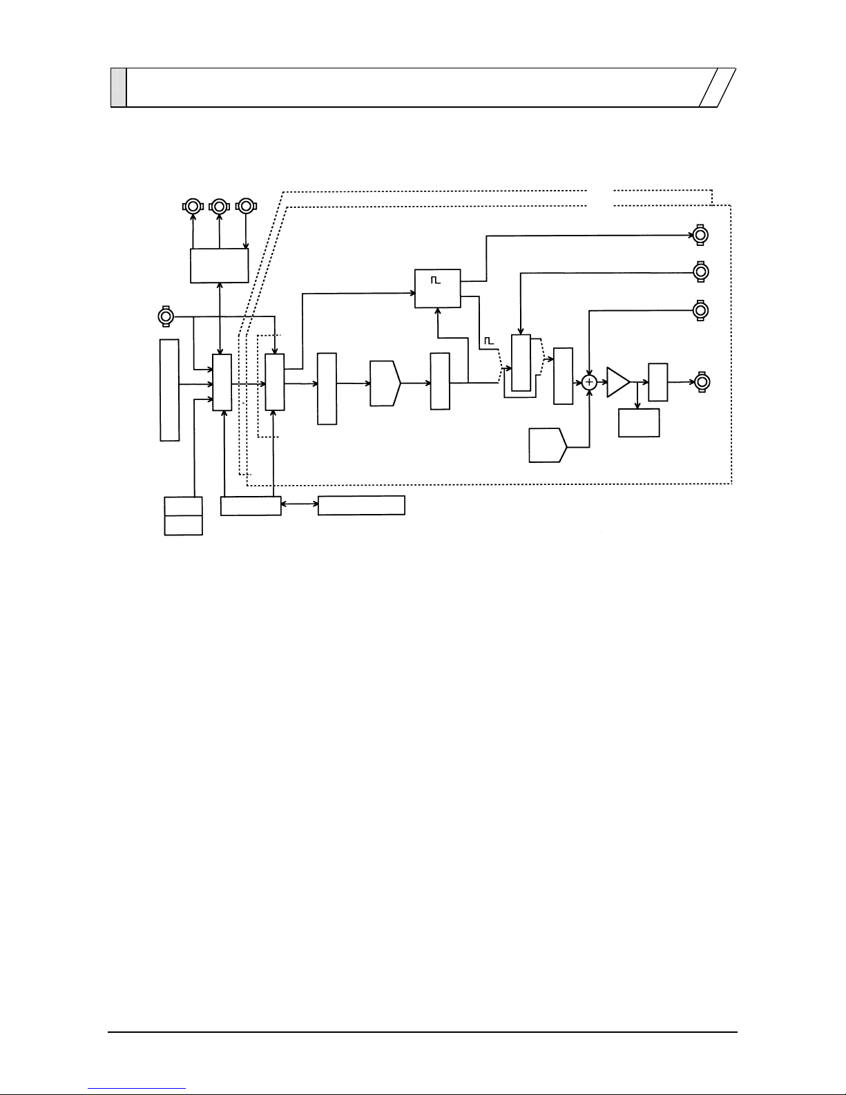
1.2 Operating principles
Block diagram
16bit 14bit
CPU
DDS
D/A
LPF
ATT
SYNC OUT
A
M IN
A
DD IN
FUNCTION OUT
GPIB
USB
Display and panel key
Waveform memory
Others
occurrence
Amplitude control
Multiplier
Clock
Synchronized operation
input/output
Isolation Offset
D/A
Over level
Detector
CH 2
CH 1
TRIG/SWEEP
IN
Sweep
input/output
zThe CPU conducts analog control for display, panel keys, remote control (GPIB, USB), DDS,
amplitude and DC offset. Sweep/internal modulation and sweep input/output control are also
conducted.
zThe clock generator produces DDS reference and CPU clock signals.
zTwo sets of circuits for DDS and analog compose two channels.
zAn isolation circuit is inserted between the CPU and DDS, causing the analog circuit to float.
zThe DDS (Direct Digital Synthesizer) uses an original LSI device and generates digital data of
the setting frequency.
zThe waveform memory converts digital data from the DDS into standard or arbitrary waveform
data. Waveform data are set from the CPU.
zThe digital to analog (D/A) converter produces an analog signal from the resulting waveform
data.
zThe lowpass filter (LPF) smoothes the stepped D/A output signal.
zAmplitude control is set by the gain control. DC offset is produced by the offset D/A converter
and the output amplifier adds and amplifies the output signal.
zThe attenuator (ATT) selects the output range by 1/10 attenuation on/off.

1-4 WF1966
1.3 Function outline
Main functions
•
Channel mode selection
Channel 1 and Channel 2 operation can be set for 2 channel independent(INDEP), 2 phase(2 PHASE), fixed
frequency difference (2 TONE), fixed frequency ratio(RATIO) or differential output(DIFF).
•
Oscillation mode selection
The oscillation type can be set for continuous(NORMAL), intermittent(BURST), sweep(SWEEP),
modulated(MODU), noise(NOISE) or DC(DC).
•
Waveform selection
The waveform type can be set for sinewave ( ), triangle waveform ( ), squarewave ( , 50 %
fixed duty), squarewave ( , variable duty), rising sawtooth ( ), descending sawtooth ( ), or
arbitrary (ARB).
•
Frequency setting
The frequency can be set by the keypad or modify dial.
The period, i.e., inverse of frequency, can also be set.
The duty and pulse width can also be set for the variable duty squarewave.
•
Amplitude setting
The amplitude can be set by the keypad or modify dial.
•
DC offset setting
The DC offset can be set by the keypad or modify dial.
•
Phase setting
Phase between channels and oscillation starting phase during burst oscillation can be set.
•
Output on/off
The waveform and sync signal output connectors are on/off switchable for each channel.
The setting prior to power off is returned at power on. Be sure to set to either on or off as required.

1.3 Function outline
WF1966 1-5
•
User units setting
Coefficients and compensation can be applied to frequency, period, amplitude, DC offset, phase and duty for
setting and displaying these in desired units. The units can be expressed by up to 4 desired characters.
•
Setting store and recall
The settings for frequency, amplitude, etc., can be stored and recalled.
The WF1966 is capable of 10 combinations store/recall.
•
Computer control
GPIB or USB enables remote control from a personal computer.
1.3 Function outline
1-6 WF1966
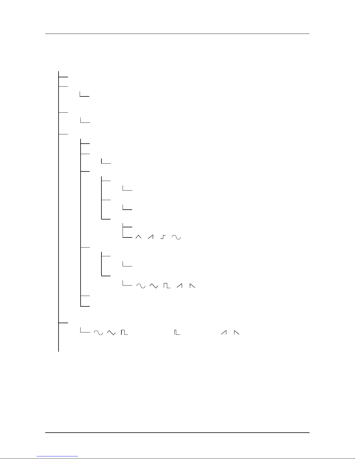
Function tree
Output
Output on/off (independent channels)
Channel mode
2 independent channels/2-phase/fixed frequency difference/fixed frequency ratio/
differential output
(Continued on the following page)
Channel selection
CH1/CH2/both channels simultaneously
Oscillation mode
Normal
Burst
Burst/trigger/gate/triggered gate
Sweep
Sweep mode
Single/continuous/gated
Sweep type
Frequency/amplitude/DC offset/phase/duty
Sweep function
Linear/log
/ / /
Modulation
Modulation type
Frequency/amplitude/DC offset/phase/duty
Modulation waveform
/ / / /
Noise
DC
Waveform
//(duty 50% fixed)/ (variable duty)/ //arbitrary waveform (ARB)

1.3 Function outline
WF1966 1-7
Output (continued from the preceding page)
Voltage
Output range
Amplitude setting
DC offset setting
High-level setting
Low-level setting
Phase
Phase between channels
User unit
Setting content
Store/recall/clear
Channel-to-channel copying
Communication
GPIB
USB
Others
Error display
Output state setting at power-on
SYNC OUT/sweep synchronized output
Trigger/gate/sweep start input
Sweep stop/restart input
Sweep X-DRIVE output
Sweep marker output
External AM input
1991 synchronized operation option
External add input
Frequency
Frequency setting
Period setting
Pulse width setting ( : for variable duty)
Duty setting ( : for variable duty)
Rise time/fall time setting ( ,: for variable duty)
Oscillation start phase
Initialization

Table of contents
Other NF Synthesizer manuals


Popular Synthesizer manuals by other brands

Kurzweil
Kurzweil K2600 BEST OF VAST - REV A Appendix

Univox
Univox mini-korg Synthesizer Service manual

Kurzweil
Kurzweil K2600 - MUSICIANS GUIDE REV A PART NUMBER 910331 CHAP... manual

Noise Engineering
Noise Engineering Lacrima Versio manual

Kurzweil
Kurzweil K2600 - MUSICIANS GUIDE REV A PART NUMBER... manual

AVP Synthesizers
AVP Synthesizers QUADWAVE user manual


