NFO Drive Sinus Series Specification sheet

NFO Drives AB
Box 35, SE-376 23 Svängsta, Sweden
Tel: +46 (0)454-370 29
Fax: +46 (0)454-32 24 14
Internet: www.nfodrives.se
Operating and
installation manual
NFO Sinus
1.5 – 11 kW 400V

NFO Drives AB. Version 3.1 eng (*) Only available together with I/O card 2
Contents
1Introduction .............................................................................................................................................................4
2Safety aspects........................................................................................................................................................... 4
3Technical data..........................................................................................................................................................5
4Installation ................................................................................................................................................................6
4.1 Typical installation.....................................................................................................................................6
4.2 Connecting mains supply......................................................................................................................... 7
4.3 Connecting motor ....................................................................................................................................8
4.4 Terminal connections...............................................................................................................................8
4.4.1 Power terminal use ..................................................................................................................8
4.4.2 Signal terminals and their use.................................................................................................9
4.4.3 Connecting serial channel RS232 ........................................................................................11
4.4.4 Connecting serial channel RS485 ........................................................................................11
4.5 Installation and ventilation.....................................................................................................................11
5Installation and programming .............................................................................................................................12
5.1 General notes ..........................................................................................................................................12
5.2 Keyboard and display .............................................................................................................................12
5.3 Operating modes.....................................................................................................................................13
5.3.1 Local mode...............................................................................................................................14
5.3.2 Programming mode................................................................................................................14
5.3.3 External mode.........................................................................................................................15
5.3.4 Serial channel mode ...............................................................................................................16
5.4 Parameter specifications........................................................................................................................17
5.5 Autotuning and motor parameters .....................................................................................................21
5.6 Setting control parameters ...................................................................................................................23
5.6.1 Control mode, parameter Mode .........................................................................................23
5.6.2 Acceleration and retardation ramp, parameters Accel and Retard ...............................24
5.6.3 Run delay, parameter RunDly ...............................................................................................24
5.6.4 Motor brake, parameter DC-Brk..........................................................................................24
5.6.5 Autostart, parameter AutoSt.................................................................................................25
5.6.6 Stop mode, parameter StMode ............................................................................................25
5.6.7 Speed regulator, parameters Kp-spd and Ti-spd................................................................25
5.6.8 Frequency bypass, parameters Byp-fr and Byp-bw ............................................................26
5.6.9 Field bus protocol, parameter AnyBus................................................................................27
5.7 RPM control with frequency estimation, Freque mode...................................................................27
5.7.1 Setpoint source for frequency, parameter OpMode........................................................27
5.7.2 Fixed frequency setpoints, parameters F-fix1 - F-fix7 ......................................................28
5.7.3 Analog frequency setpoint range, parameters Fr-min and Fr-max.................................28
5.8 RPM regulation with speed estimation, Speed mode.......................................................................28
5.8.1 Setpoint source for speed, parameter OpMode...............................................................29
5.8.2 Fixed speed setpoints, parameters C-fix1 - C-fix7...........................................................29

NFO Drives AB. Version 3.1 eng (*) Only available together with I/O card 3
5.8.3 Analog speed setpoint range, parameters Sp-min and Sp-max ......................................29
5.9 Torque regulation, Torque mode .........................................................................................................30
5.9.1 Torque regulation setpoint source, parameter OpMode ...............................................30
5.9.2 Fixed torque setpoints, parameters T-fix1 - T-fix7...........................................................30
5.9.3 Analog torque setpoint range, parameters Tq-min and Tq-max ....................................31
5.10 Process regulation, PI Reg mode ..........................................................................................................31
5.10.1 Setpoint source, process regulation ..................................................................................32
5.10.2 Fixed process regulator setpoints, parameters R-fix1 - R-fix7 ......................................33
5.10.3 Analog regulator setpoint from temperature sensor (*)...............................................33
5.10.4 Regulator setting, parameters RegAmp, RegKp and RegTi ..............................................33
5.11 Motor safety functions ...........................................................................................................................33
5.11.1 PTC input.................................................................................................................................34
5.11.2 Power monitor .......................................................................................................................34
5.12 Output signals to display (*) .................................................................................................................34
5.12.1 Function relay (*) ...................................................................................................................35
5.12.2 Analog voltage output (*).....................................................................................................35
5.12.3 Frequency output (*).............................................................................................................35
5.13 Reset to factory settings........................................................................................................................36
5.14 Alarm and fault procedures ..................................................................................................................36
5.14.1 Fault log....................................................................................................................................36
5.14.2 Fault messages ........................................................................................................................37
6Brake chopper and power surge regulator.....................................................................................................40
7Getting started ......................................................................................................................................................41
7.1 Running in local mode............................................................................................................................41
7.2 Running at fixed frequency....................................................................................................................41
7.3 Running from terminal, fixed setpoint................................................................................................41
7.4 Running with analog setpoint................................................................................................................42
7.5 Torque control with analog setpoint..................................................................................................42
7.6 Process regulation with analog setpoint.............................................................................................42
8Your own parameter settings ............................................................................................................................43

NFO Drives AB. Version 3.1 eng (*) Only available together with I/O card 4
1 Introduction
The frequency inverter described in this operating manual is used for speed (RPM) and torque control of three-phase
induction motors. This manual tells you how to install and use the inverter.
Read the manual carefully before installing the inverter, to ensure you install it correctly and get the maximum performance
out of it.
NFO Sinus is a frequency inverter which uses the patent "Natural field orientation" system to give perfect speed control of
induction motors all the way from zero to full speed.
The inverter also has a patented switch connection that ensures the motor is fed a perfect sinus voltage at all times under all
operating conditions.
2 Safety aspects
Always disconnect the inverter from the mains supply before working on any electrical or mechanical installation
components.
Installation, maintenance and repairs must always be conducted by staff adequately trained and experienced for the purpose.
Modifying or replacing any components of the inverter or its accessories will render the inverter warranty null and void.
Should the need for any modifications or replacements arise, always contact NFO Drives AB.
Components in the power section and some components in the signal section are connected to the mains supply when the
inverter is.
Touching any components with the mains supply connected can be fatal! Always disconnect the mains
supply before removing the front panel. Never open the inverter side panels.
WARNING! Even when disconnected from the mains supply, the inverter may still be live on account of its buffer
capacitors. Always wait at least five minutes, and take test readings between the + and – terminals to make sure no
voltage remains before starting working on the inverter.
The inverter must always be earthed when mains supply is connected.

NFO Drives AB. Version 3.1 eng (*) Only available together with I/O card 5
3 Technical data
Motor output
Motor rating (kW) 1.5 2.2 3 4 5.5 7.5 11
Continuous rating (A) 3.5 4.9 6.7 8.8 11.1 14.8 21.5
Maximum rating (A) 4.2 5.8 8.0 10.5 13.3 17.7 25.8
Output voltage wave form Sinus
Output frequency 0 – 150 Hz
Operating mode 4 quadrant (with external brake resistance, as required)
Inverter input
Supply voltage 3 x 380 – 440V +/-10%
Frequency 50/60 Hz (+/-10%)
Control inputs
Setpoints 0-10V, 2-10V, ±10V, 0-20mA, 4-20mA, ±20mA, potentiometer 10kΩ,
7 set frequencies selectable from terminal with positive or negative logic
Actual values 0-10V, 2-10V, ±10V
Local mode Keyboard: Forward, Reverse, Stop
Acceleration time 0.2 – 500s
Retardation time 0.2 – 500s
Signal outputs
Voltage (*) 0 – 10V
Frequency (*) 0 – 32kHz, open collector
Relay Fault relay, operating relay, function relay (*)
Control modes
Frequency control 0 – 150 Hz
Speed control 0 – 9000 rpm
Torque control 1 – 200% of nominal motor torque, depending on inverter capacity
Process control PI with feedback, temperature sensor PT1000 for recording temperature at constant
pressure control in the ventilation system (*), 24V supply to external sensors (*)
Motor safety
Thermistor input PTC or Klixon
Power monitor Switch off if motor is loaded over rated power for a long time
Ambient conditions
Ambient temp. -10 to +40 °C
Storage temp. -20 to +60 °C
Humidity 0 – 90%, non-condensing
Protection class IP20
Dimensions 365 (+47) x 265 x 70
365 (+47) x 265 x 123 365 (+47) x 265 x 203
Weight 4.9 kg 6.5 kg 14 kg
Functions marked (*) only available together with I/O card.
NFO Drives AB. Version 3.1 eng (*) Only available together with I/O card 6
4 Installation
All terminals are accessed via the lower front panel, fitted with four screws, remove.
Please note that the inverter must not be run for more than one minute with the front panel removed, as this affects the
airflow through it.
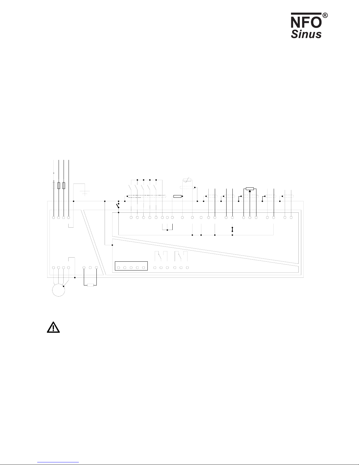
4.1 Typical installation
M
3~
UVWPE
L1 L2
L1
7
RXD
8
TXD
4
RTS
3
CTS
5
GND
RS 232
Modular contact
11312 4310
Current input, 0/4-20mA
Potentiometer, 10k
Ω
Voltage input, 0/2-10V
Run signal start/stop
Direction of rotation
Fixed frequency 1
Fixed frequency 2
Fixes frequency 3
5 14 6 15 26 25
REV
PTC
FIX1
FIX2
FIX3
RUN
SIO- SIO+
+- B
Fault relay/
alarm output
RS 485
L3 PE
Braking
resistance
(optional)
I/O ground
16 7
Run
indicator
27
Digital inputs
max 24V
+-
82817
L2 L3 PE
920 21 22 23
+12V
2
S3
+-
18 29
S4
Motor safety thermistor (PTC)
PTC pre-connection resistance 3,9 k
Ω
11 24
Actual value input
process regulator
VOLTAGE
Fig.1. Typical configuration
Warning! If there is a run signal to the inverter (terminal 5), the inverter will start up when power is applied.
Terminals 21, 22, 23 and 24 (I/O ground) can be connected galvanically to PE via jumper S4 (not supplied with installation).
These terminals may vary in terms of potential by up to 100 V from PE if S4 is not fitted. The RS 232 contact is always
connected galvanically to PE.
The negative power input (terminal 2) is connected to I/O ground (terminals 21 - 24) via jumper S3 (supplied fitted). Remove
this jumper and the common-mode voltage at the power input (terminals 2 and 10) may vary by up to +/-24V from I/O
ground. This is designed to be used when a number of current controlled units are connected in series.
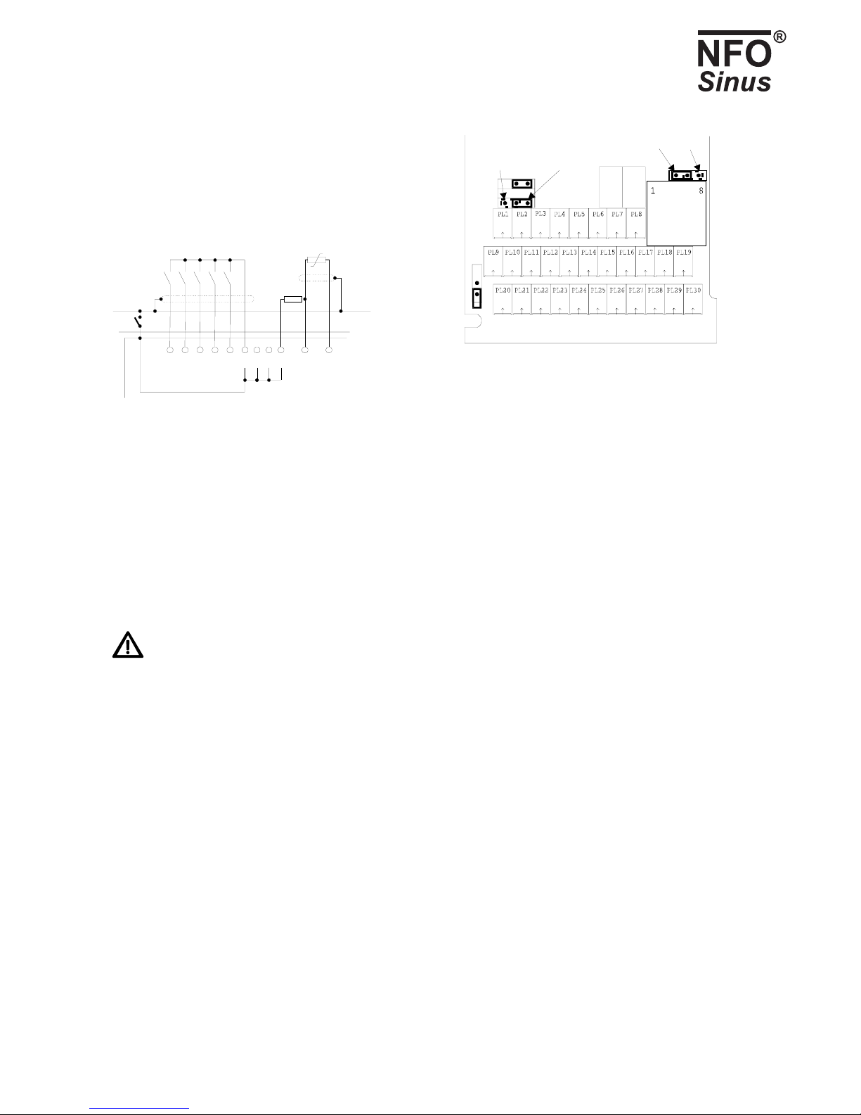
The inverter can be configured for negative logic at the digital inputs (terminals 5, 6, 14, 15 and 26) by moving jumper S1 (see
Fig. 3). The inputs are then made active by connecting them to the I/O ground (terminals 21 – 24), see Fig. 2 .
NFO Drives AB. Version 3.1 eng (*) Only available together with I/O card 7
Run signal start/stop
Direction of rotation
Fixed frequency 1
Fixes frequency 2
Fixed frequency 3
5 14 6 15 26
FWD/
REV
FIX1
FIX2
FIX3
RUN
I/O ground
21 22 23 24
S4
25 20
Motor safety resistor (PTC)
PTC pre-connection resistance 3,9 k
Ω
+12V
Pos. logicNeg. logic
RS 232
RS 485RS 232
S1S2 S3
S4
S5
Fig. 2. Connection via negative logic
(jumper S1 moved)
Fig. 3. Jumper locations (shown as
supplied)
All signal lines should be installed with shielded cables, with the cable shields being connected to the safety earth at one end.
The reason for recommending shielding is that signal cables laid alongside power cables are prone to interference, so the
inverter can be fed incorrect setpoints.
When running with a potentiometer, this should have a tolerance of better than 5% so the setpoint is not outside the
permitted range. The inverter can be configured to give an alarm if the setpoint is out of limits using the Ain Fail fault.
An external braking resistance must be fitted if the retardation time is less than 5 sec, see section 6.
If in any doubt as to installation, always contact NFO Drives AB.
4.2 Connecting mains supply
Three-phase feed inverters are connected to a three-phase mains network at a nominal voltage of 380 – 440 V 50/60 Hz
between terminals L1, L2, L3 and PE. PE = ground, see Fig.1.
Recommended slow-blowing fuses for three-phase supply:
1.5 kW 2.2 kW 3 kW 4 kW 5.5 kW 7.5 kW 11 kW
6 A 10 A 10 A 16 A 16 A 25 A 35 A
With the mains supply connected correctly and the motor running, the inverter draws less than 2 mA earth current in the
PE core.

NFO Drives AB. Version 3.1 eng (*) Only available together with I/O card 8
4.3 Connecting motor
Connect motor cables between terminals U, V, W and PE.
The nominal motor voltage for three-phase fed inverters is 400V, so a motor with a nominal voltage of 400 V Y / 230 V D
must be Y-connected and a motor with nominal voltage of 690V Y / 400 V D must be D-connected.
Current EMC standards can be met without shielded motor cable if the inverter is correctly installed
otherwise. There is no limit on motor cable length, as the inverter always supplies a sinus voltage to the
motor; but voltage drop in cables must be allowed for.
4.4 Terminal connections
B - + L3 L2 L1 PE PE W V U
Fig. 4. Power terminal appearance, three-phase supply
4.4.1 Power terminal use
Terminal Function Description
B Braking resistance Connection for external braking resistance (between B and +)
- - DC link voltage. Nominal voltage:
+ + At three-phase feed 400 V: 565 V DC
L3
L2 Mains supply, phases Mains supply 3 x 380–440V
L1
PE Safety earth Power supply safety earth
PE Safety earth Safety earth connection motor
W
V Motor connection Motor connection
U
Table 1. Use of power terminals
If installing a number of inverters with one or more running in regenerative mode, the inverter DC links (terminals + and -)
can be connected to one another so these inverters supply energy to the others. Thanks to component tolerances in the
inverter, the link voltage may vary slightly from one model to another, so an equalising resistance and ultra-fast fuse must be
fitted to each line. Contact NFO Drives AB for correct dimensions.

NFO Drives AB. Version 3.1 eng (*) Only available together with I/O card 9
4.4.2 Signal terminals and their use
Term. Function Description
1 +12V
9 +12V +12V unregulated voltage to digital inputs, max 50mA
20 +12V
21 COMMON
22 COMMON I/O ground
23 COMMON
24 COMMON
5 RUN Run signal
14 REV Direction of rotation, see Table 6.
6 FIX1 Select fixed frequency, see Table 6.
15 FIX2 Select fixed frequency, see Table 6.
26 FIX3 Select fixed frequency, see Table 6.
25 PTC PTC motor protection, requires resistance at 3.9 kΩconnected to +12 V
12 PLUS POT Potentiometer input 10 kΩ, positive limit, see also Table 7.
13 POT Potentiometer input 10 kΩ, central takeoff
4 MINUS POT Potentiometer input 10 kΩ, negative limit
3 VOLTAGE Voltage setpoint input, see Table 7.
10 CURRENT + Current setpoint input, positive potential, see Table 7.
2 CURRENT - Current setpoint input, negative potential.
28 ALARM A
17 ALARM B Fault relay, potential-free contact max 1 A, 50 V DC.
8 ALARM C If fault in inverter, terminals 17 and 18 close.
27 MOTOR_RUN A
16 MOTOR_RUN B Run indication, potential-free contact max 1 A, 50 V DC.
7 MOTOR_RUN C Terminals 7 and 16 are closed when motor is running.
18 SIO- RS 485, negative input
29 SIO+ RS 485, positive input
11 ACT_VOLTAGE Process regulator actual value input.
30
19
Table 2. Signal terminals and their use
Digital inputs (terminals 5, 6, 15, 25 and 26) under positive logic:
Maximum input voltage: 30V
Switch level: approx. 4V
NFO Drives AB. Version 3.1 eng (*) Only available together with I/O card 10
Digital inputs (terminals 5, 6, 15, 25 and 26) under negative logic:
Maximum input voltage: 30V
Switch level: approx. 7.5V
I/O ground
(plint 21 - 24)
55
62
Analog
output
0-10V,
max. 3mA
Frequency
output
Open collector
max. 24V,
10m
A
58 60
57 59 61 63
+5V
56
54 67 65 66
+24V
52 75
External power
supply 24V, max 40mA
Passiv
e
temp. sensor
PT1000
+
-
51 53
Function-
relay
50
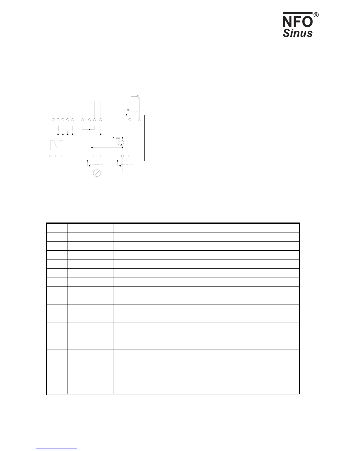
Fig. 5. Connecting expansion board
Term. Function Description
50 RELAY B Function relay, potential-free contact max. 2 A, 50 V DC, 50 W. see section 5.12.1
51 RELAY A Function relay
52 +24V +24V, max. 40mA
53 RELAY C Function relay
54 +24V
55 COMMON Reference ground
56 FREQ OUT Frequency output, max. 24V 10 mA ,Open Collector, see section 5.12.3
57 COMMON
58 COMMON
59 COMMON
60 VOLT OUT Analog voltage output, max. 10V 3mA, see section 5.12.2
61 COMMON
62 COMMON
63 COMMON
65 COMMON
66 PT1000 Temperature sensor PT1000, process regulation, see section 5.10
67 COMMON
75 +24V
Table 3. Signal terminals and their use, I/O board.

NFO Drives AB. Version 3.1 eng (*) Only available together with I/O card 11
4.4.3 Connecting serial channel RS232
The inverter can be controlled via a type RS232 serial channel. Jumper S5 must then be installed on the left (installed as
supplied) as shown in Fig. 3. Connection is made to the 8-pin modular contact, pins numbered 1 to 8 from left to right. Table
4 shows examples of how connection can be made to either of the serial ports (COM1 or COM2) on a PC. These interfaces
also usually work for other kinds of equipment with these types of contacts. There is a separate manual available describing
the control protocol, contact NFO Drives AB.
Inverter
modular contact
Signal
direction
Description 9-p DSUB
COM1 (PC)
25-p DSUB
COM2 (PC)
Signal
name
7 ÆData from inverter to
higher-level system
2 3 RXD
8 ÅData from higher-level
system to inverter
3 2 TXD
4 ÅSet to 1s by higher-level
system when sending to
inverter
7 4 RTS
3 ÆSet to 0s by inverter
when sending, otherwise
1s
8 5 CTS
5 Signal ground 5 7 GND
Table 4. Connecting series channel RS232.
4.4.4 Connecting serial channel RS485
The inverter can also be controlled via an RS485 type serial channel. Jumper S5 must then be installed on the right as shown
in Fig. 3. Connection is made to terminals 18 (SIO-) and 29 (SIO+). Any terminal resistance must be connected to the
terminal separately.
4.5 Installation and ventilation
The inverter is designed to be installed in equipment cabinets with adequate cooling with a throughflow of cold air. It is
important to ensure that air does not recirculate inside the cabinet. The cooling air temperature must not exceed 40°C.
An 80 mm clearance must be left above and below the inverter to ensure sufficient air passes through it.
The inverter must not be installed such that outlet air from another inverter or equipment blows directly into the
inverter air intake.
To ensure a correct airflow through the inverter, it must be installed hanging vertically against a flat surface. If no flat surface
is available, the installer must have this fitted separately.
If a number of inverters are to be installed side by side, a 20 mm gap must be left between inverters to ensure air circulates
properly.

NFO Drives AB. Version 3.1 eng (*) Only available together with I/O card 12
It can be fitted to the installation plate with 4 x M5 screws.
Please note: When installing, it is essential to ensure that no foreign bodies such as drilling swarf or screws fall into
the inverter, as this may cause shorting.
5 Installation and programming
5.1 General notes
The inverter can be used in four control modes:
• Speed regulation of an induction motor with frequency monitoring (motor speed compensated for load variations) with
a fixed (digital) or analog setpoint, see section 5.7 for more details. The motor's estimated rotor frequency is shown on
the display. This operating mode is called Freque and is supplied installed.
• Speed regulation for an induction motor with speed calculation (motor speed compensated for load variations) with a
fixed (digital) or analog setpoint, see section 5.8 for more details. The motor's estimated speed is shown in the display.
This mode is called Speed
• Torque control for an induction motor with a fixed (digital) or analog setpoint, see section 5.9. This operating mode is
called Torque.
• As a process regulator with feedback from a process controlled by an induction motor, see section 5.10. This mode is
called PI-reg.
The inverter as supplied is set up to operate a motor with nominal data as follows:
Power supply 3 x 400V:
1.5 kW: 400 V Y/230 V D 3.5/6.1 A, Y-connected, 4-pole
2.2 kW: 400 V Y/230 V D 4.9/8.5 A, Y-connected, 4-pole
3 kW: 400 V Y/230 V D 6.5/9.2 A, Y-connected, 4-pole
4 kW: 690 V Y/400 V D 5.1/8.8 A, D-connected, 4-pole
5.5 kW: 690 V Y/400 V D 6.4/11.1 A, D-connected, 4-pole
7.5 kW: 690 V Y/400 V D 8.8/15.2 A, D-connected, 4-pole
11 kW: 690 V Y/400 V D 12.4/21.5 A, D-connected, 4-pole
If using other motor type, the motor parameters must be changed, see section 5.5, Autotuning and motor
parameters.
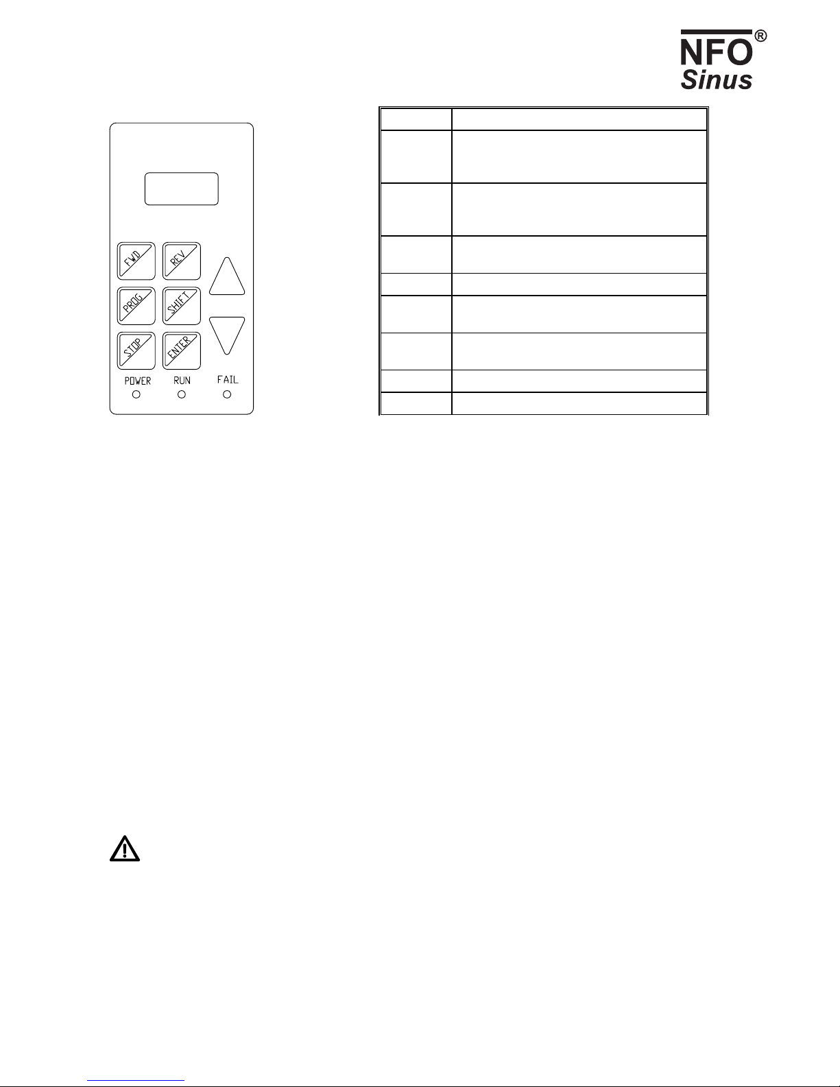
5.2 Keyboard and display
The diagram and table below shows what the keyboard looks like and the key functions generally.
NFO Drives AB. Version 3.1 eng (*) Only available together with I/O card 13
LCD display
2 x 8 tecken
Button Function
FWD Local mode: start motor clockwise.
Programming mode: scroll forward through
parameters or parameter groups.
REV Local mode: start motor anti-clockwise.
Programming mode: scroll back through
parameters or parameter groups.
PROG Go to/exit programming mode. Go from
parameters to parameter groups.
SHIFT Increase increment by ⇑and ⇓.
STOP Stop motor and switch to local mode.
Used together with SHIFT, starts motor.
ENTER Set parameter as amended or go to parameter
group.
⇑Increase parameter when changing.
⇓Decrease parameter when changing.
Fig. 6. Keyboard Table 5. Button functions
The value of a given parameter can be increased or decreased by pressing ⇑or ⇓. When adjusting parameters, these have set
increments (how much they change by each time the button is pressed). To increase this increment, press SHIFT and hold
down. Both ⇑and ⇓and SHIFT + ⇑and SHIFT + ⇓are repetitive. Pressing any of these key combinations and holding them
down increases the repetition frequency successively.
When any parameter is changed, a * appears on the right of the first line of the display. This means the parameter has not
yet been saved in the inverter's memory. To save the value, press ENTER, then the * disappears.
The indicator lights at the bottom of the keyboard have meanings as follows:
POWER Indicates the inverter is live.
RUN Lights up when the motor is running.
FAIL Inverter faulty
5.3 Operating modes
When starting and initiating the inverter, the software version number will appear for a few seconds. The inverter then goes
to external mode and waits for the start command, the display reads Ext Stby. To give the start command, activate terminal 5
(RUN).
The inverter starts automatically when power is switched on if terminal 5 (RUN) is active and parameter
AutoStart=ON (supplied installed).
You can switch to local mode at any time by pressing STOP, which disconnects the motor.
To switch from any mode to programming mode or vice versa, press PROG. If switching to programming mode from
external or serial channel mode, motor control is maintained as in those modes.

NFO Drives AB. Version 3.1 eng (*) Only available together with I/O card 14
5.3.1 Local mode
When motor is running, you can switch to local mode (stop motor) by pressing STOP at any time.
In local mode, the display reads Stop and a frequency. The frequency displayed can be adjusted and saved in the inverter's
memory. Pressing FWD or REV accelerates the motor clockwise or anti-clockwise, the display reads Acc. Final fr. appears
once the frequency has been reached. When the button is released, the motor is retarded if parameter stMode is in Brake
position, the display reads Ret. If stMode is in the Release position, the motor runs down. If the inverter is run at frequency
0.0, the display will read St still provided the motor is stopped. The frequency can also be increased and decreased in
operation by pressing ⇑or ⇓. This way of running the motor is only designed to be used when starting.
The motor can also be started by pressing SHIFT + FWD or SHIFT + REV, in which case it will continue to run even once
the keys are released. Once again, you can increase or reduce the frequency by pressing ⇑, ⇓, SHIFT + ⇑or SHIFT + ⇓. To
stop the motor, press STOP or FWD.
To switch to external mode, press SHIFT + STOP. You can also switch if terminal 5 (RUN) goes from active to inactive or is
active and goes inactive.
To switch to programming mode, press PROG.
To switch from local mode to serial channel mode, use command from serial channel.
5.3.2 Programming mode
This mode is used to change and read off parameters from the inverter. The inverter parameters are divided into parameter
groups, as shown in Table 8.
To access parameter groups, press PROG. To scroll forwards or backwards between parameter groups, use FWD and REV.
To access parameters within a group, press ENTER. To go back to parameter groups, press PROG. To exit programming
mode, press PROG again.
Pressing SHIFT + PROG at a parameter exits programming mode immediately. Pressing SHIFT + PROG again takes you
directly back to the last parameter.
To scroll forwards or backwards through parameters in a group, use FWD and REV. The first line of the display shows the
current parameter's name and the second line its current value.
If terminal 5 (RUN) is active, the inverter can be started by pressing SHIFT + STOP or stopped by pressing STOP, in which
case the inverter will remain in programming mode.
An R (Read only) appears in the top right hand corner of the display if the parameter concerned is read-only. This may be
because the parameter shows a status value or cannot be varied because the motor is running.
If switching to programming mode from external or serial channel mode, motor control remains in that mode; but
parameters cannot be modified when the motor is running

NFO Drives AB. Version 3.1 eng (*) Only available together with I/O card 15
5.3.3 External mode
When running in external mode, line one of the display shows the inverter status, and line two its current frequency. If the
inverter status reads Ext Stby, this indicates the inverter is ready to run and is waiting for a run signal. Ext Run appears when
the inverter is running.
The source for the setpoint is governed by the parameter OpMode for the operating mode concerned as in Table 12, Table
13, Table 14 and Table 17. Selecting OpMode: Terminal enables the setpoint source to be selected from the signal terminals as
in Table 6. If using analog setpoints, the signal type is selected using parameter AinSet from the Control parameter group as in
Table 7. Setpoint sources can be changed on the run.
Analog F means run counter-clockwise at the lowest setpoint at min and the highest setpoint at max run.
Analog R likewise, but clockwise.
Fix-1 F means run clockwise with setpoint from corresponding fixed value parameter for the control mode concerned,
Fix-1 R likewise but running counter-clockwise, and so on.
Fixed value parameters can be changed on the run, in which case the new setpoint applies immediately.
To switch to local mode (motor released), press STOP.
To switch to programming mode, press PROG.
Function REV
(14)
FIX1
(6)
FIX2
(15)
FIX3
(26)
RUN
(5)
Analog F 0 0 0 0 1
Analog R 1 0 0 0 1
Fix-1 F 1 1 0 0 1
Fix-2 F 1 0 1 0 1
Fix-3 F 1 1 1 0 1
Fix-4 F 1 0 0 1 1
Fix-5 F 1 1 0 1 1
Fix-6 F 1 0 1 1 1
Fix-7 F 1 1 1 1 1
Fix-1 R 0 1 0 0 1
Fix-2 R 0 0 1 0 1
Fix-3 R 0 1 1 0 1
Fix-4 R 0 0 0 1 1
Fix-5 R 0 1 0 1 1
Fix-6 R 0 0 1 1 1
Fix-7 R 0 1 1 1 1
Table 6. Digital input settings at signal terminals 5, 6, 14, 15 and 26.

NFO Drives AB. Version 3.1 eng (*) Only available together with I/O card 16
Parameter AinSet
setting
Analog value Input (terminal)
0-10V Voltage 0-10V 3
2-10V Voltage 2-10V 3
+/-10V Voltage +/- 10V 3
0-20mA Current 0-20mA 10 and 2
4-20mA Current 4-20mA 10 and 2
+/-20mA Current +/- 20mA 10 and 2
Pot 10k Potentiometer 10kΩ12, 13 and 4
Table 7. Settings for analog setpoint inputs at signal terminals
5.3.4 Serial channel mode
Switching to serial mode is done by giving a command via the serial channel. This can only be done with the motor stopped
in local mode and immediately after startup with the inverter in the Ext Stby position, waiting for a run signal.
To return to local mode, use serial channel command or press STOP.
In serial channel mode, the inverter can be controlled via all the setpoint sources described in section 5.3.3 external mode.
There are also facilities for reading and amending parameters in the inverter.
For using serial channel, see separate manual available. Contact NFO Drives AB.

NFO Drives AB. Version 3.1 eng (*) Only available together with I/O card 17
5.4 Parameter specifications
Parameters are divided into parameter groups, as shown in the table below:
Motor Control Freque Speed Torque PI Reg Output Serial Status Error
P-Nom Mode OpMode OpMode OpMode OpMode ReMode SioAdr I-rms E-logg
U-Nom Accel F-fix1 C-fix1 T-fix1 R-fix1 ReFreq SiBaud DClink RstDly
f-Nom Retard F-fix2 C-fix2 T-fix2 R-fix2 V-Out SiProt FrqSet TrTime
N-Nom RunDly F-fix3 C-fix3 T-fix3 R-fix3 V-Max SioTot FrqAct AC Fail
I-Nom DC-Brk F-fix4 C-fix4 T-fix4 R-fix4 F-Out SpdSet Temp Hi
cos ϕAinSet F-fix5 C-fix5 T-fix5 R-fix5 F-Max SpdAct PTC Temp
Tuning AutoSt F-fix6 C-fix6 T-fix6 R-fix6 TrqSet OverLoad
R-stat StMode F-fix7 C-fix7 T-fix7 R-fix7 TrqAct Ain Fail
R-rot Kp-spd Fr-min Sp-min Tq-min Setmin RegSet DC Low
L-main Ti-spd Fr-max Sp-max Tq-max Setmax RegAct DC High
Sigma Byp-fr Max-sp Actmin PT1000 GND Fail
I-magn Byp-bw Actmax M-Temp IMagnLow
I-limt AnyBus T-min OpTime Cur Low
T-max RnTime Cur High
RegAmp RunFail
RegKp BusFail
RegTi
Min-fr
Max-fr
Unit
AinAct
Table 8. Parameter groups and parameters.
Only the parameter groups for the run mode selected are displayed, i.e. either Freque, Speed, Torque or PI reg.
The table below shows all inverter parameters, divided into parameter groups.
Typ = Init means parameters can only be changed via initialising in local mode.
Typ = Init/Run means parameters can be changed in any mode.
Typ = Read means parameters are read-only.
NFO Drives AB. Version 3.1 eng (*) Only available together with I/O card 18
Name Description Section Default value Range Type
P-Nom Nominal motor output 5.5 0.01 – 100kW Init
U-Nom Nominal motor voltage 5.5 1 – 1000V Init
f-Nom Nominal motor frequency 5.5 1 – 327Hz Init
N-Nom Nominal motor speed 5.5 5 – 32765rpm Init
I-Nom Nominal motor current 5.5 I-magn – 100.0A Init
cos ϕMotor cos ϕ5.5
Table 10
0.01 – 1.00 Init
Tuning Autotuning command 5.5 Init
R-stat Motor stator resistance 5.5 Init
R-rot Motor rotor resistance 5.5 Init
L-main Motor main inductance 5.5 Table 11 Init
Sigma Motor leak inductance 5.5 Init
I-magn Magnetisation current setpoint (RMS) 5.5 0 – min(I-nom, I-limt) Init
I-limt Maximum motor current (RMS) 5.5 Init/Run
Mode Control mode 5.6.1
Freque = speed control with frequency estimation 5.7
Speed = rpm control with speed estimation 5.8
Torque = torque control 5.9
PI-reg = process control mode 5.10
Speed Freque
Speed
Torque
PI-reg
Init
Accel Acceleration time from 0 to f-Nom Hz 5.6.2 30.0 s 0.2 - 500.0 s Init/Run
Retard Retardation time from f-Nom to 0 Hz 5.6.2 30.0 s 0.2 - 500.0 s Init/Run
RunDly Start delay 5.6.3
Delay in seconds from when power is applied until motor can
start.
0 s 0 – 3600 s Init/Run
DC-Brk Motor DC braking before startup. 5.6.4
Time in seconds for which motor is braked before startup.
0 s 0 – 3600 s Init/Run
AinSet Type of setpoint at analog input (terminals 3, 10 or 24)
0-10V 0-10V
2-10V
+/-10V
0-20mA
4-20mA
+/-20mA
Pot 10k
AutoSt Autostart mode 5.6.5
OFF = Inverter awaiting flank on RUN after power applied.
ON = motor starts as soon as power is applied if RUN is
active.
WARNING: if there is a run signal to the inverter, it
will start when power is applied.
ON OFF
ON
Init/Run
StMode Stop mode 5.6.2
Brake = motor brakes as Retard.
Release = motor runs down.
Brake Brake
Release
Init/Run
Kp-spd Amplifier component speed regulator 5.6.7 0.100 0,01 – 1.000 Init/Run

NFO Drives AB. Version 3.1 eng (*) Only available together with I/O card 19
Ti-spd Integrator component speed regulator 5.6.7 1.00 0 – 10.00 s Init/Run
Byp-fr Bypass frequency 5.6.8 0.0 Hz 0.0-150.0 Hz Init/Run
Byp-bw Bypass frequency bandwidth 5.6.8 0.0 Hz 0.0-150.0 Hz Init/Run
AnyBus Field bus protocol See separate manual Init/Run
OpMode Setpoint source, frequency 5.7.1 Terminal Table 12 Init/Run
F-fix1 Fixed frequency 1 5.7.2 10.0 Hz 0.0-150.0 Hz Init/Run
F-fix2 Fixed frequency 2 5.7.2 20.0 Hz 0.0-150.0 Hz Init/Run
F-fix3 Fixed frequency 3 5.7.2 30.0 Hz 0.0-150.0 Hz Init/Run
F-fix4 Fixed frequency 4 5.7.2 40.0 Hz 0.0-150.0 Hz Init/Run
F-fix5 Fixed frequency 5 5.7.2 50.0 Hz 0.0-150.0 Hz Init/Run
F-fix6 Fixed frequency 6 5.7.2 60.0 Hz 0.0-150.0 Hz Init/Run
F-fix7 Fixed frequency 7 5.7.2 70.0 Hz 0.0-150.0 Hz Init/Run
Fr-min Lowest frequency when running with analog setpoint. 5.7.3 0.0 Hz 0.0-150.0 Hz Init/Run
Fr-max Highest frequency when running with analog setpoint. 5.7.3 50.0 Hz 0.0-150.0 Hz Init/Run
OpMode Setpoint source, speed 5.8.1 Terminal Table 13 Init/Run
C-fix1 Fixed speed 1 5.8.2 300 rpm 0-9000 rpm Init/Run
C-fix2 Fixed speed 2 5.8.2 600 rpm 0-9000 rpm Init/Run
C-fix3 Fixed speed 3 5.8.2 900 rpm 0-9000 rpm Init/Run
C-fix4 Fixed speed 4 5.8.2 1200 rpm 0-9000 rpm Init/Run
C-fix5 Fixed speed 5 5.8.2 1500 rpm 0-9000 rpm Init/Run
C-fix6 Fixed speed 6 5.8.2 1800 rpm 0-9000 rpm Init/Run
C-fix7 Fixed speed 7 5.8.2 2100 rpm 0-9000 rpm Init/Run
Sp-min Lowest speed when running with analog setpoint. 5.8.3 0 rpm 0-9000 rpm Init/Run
Sp-max Highest speed when running with analog setpoint. 5.8.3 1500 rpm 0-9000 rpm Init/Run
OpMode Setpoint source, torque 5.9.1 Terminal Table 14 Init/Run
T-fix1 Fixed torque 1 5.9.2 10.0 % 1 – 200 % Init/Run
T-fix2 Fixed torque 2 5.9.2 20.0 % 1 – 200 % Init/Run
T-fix3 Fixed torque 3 5.9.2 30.0 % 1 – 200 % Init/Run
T-fix4 Fixed torque 4 5.9.2 40.0 % 1 – 200 % Init/Run
T-fix5 Fixed torque 5 5.9.2 50.0 % 1 – 200 % Init/Run
T-fix6 Fixed torque 6 5.9.2 60.0 % 1 – 200 % Init/Run
T-fix7 Fixed torque 7 5.9.2 70.0 % 1 – 200 % Init/Run
Tq-Min Lowest torque when running with analog setpoint 5.9.3 10.0 % 1 – 200 % Init/Run
Tq-Max Highest torque when running with analog setpoint 5.9.3 100.0 % 1 – 200 % Init/Run
Max-sp Maximum speed under torque control. 5.9 1500 rpm 0-9000 rpm Init/Run
OpMode Setpoint source, regulator 5.10.1 Terminal Table 17 Init/Run
R-fix1 Fixed setpoint 1 5.10.2 100.0 -2000.0 - 2000.0 Init/Run
R-fix2 Fixed setpoint 2 5.10.2 200.0 -2000.0 - 2000.0 Init/Run
R-fix3 Fixed setpoint 3 5.10.2 300.0 -2000.0 - 2000.0 Init/Run
R-fix4 Fixed setpoint 4 5.10.2 400.0 -2000.0 - 2000.0 Init/Run
R-fix5 Fixed setpoint 5 5.10.2 500.0 -2000.0 - 2000.0 Init/Run
R-fix6 Fixed setpoint 6 5.10.2 600.0 -2000.0 - 2000.0 Init/Run
R-fix7 Fixed setpoint 7 5.10.2 700.0 -2000.0 - 2000.0 Init/Run
Setmin Value at min. input signal from setpoint input 5.10.1, 5.10.3 0.0 -2000.0 - 2000.0 Init/Run

NFO Drives AB. Version 3.1 eng (*) Only available together with I/O card 20
Setmax Value at max. input signal from setpoint input 5.10.1, 5.10.3 1000.0 -2000.0 - 2000.0 Init/Run
Actmin Value at min. input signal from actual value input 5.10 0.0 -2000.0 - 2000.0 Init/Run
Actmax Value at max. input signal from actual value input 5.10 1000.0 -2000.0 - 2000.0 Init/Run
T-min Min. temperature 5.10.3 -20 °C -100 – 100 °CInit/Run
T-max Max. temperature 5.10.3 20 °C -100 – 100 °CInit/Run
RegAmp Amplifies process regulator 5.10.4 1 -20 – 20 Init/Run
RegKp Proportional component process regulator 5.10.4 0.00 0.00 – 20.00 Init/Run
RegTi Integrator component process regulator 5.10.4 10.0 s 1.0 – 200.0 s Init/Run
Min-fr Min. frequency from regulator 5.10 0.0 Hz 0.0 – 150.0 Hz Init/Run
Max-fr Max. frequency from regulator 5.10 50.0 Hz 0.0 – 150.0 Hz Init/Run
Unit Regulator units 5.10 Pa Table 15 Init/Run
AinAct Scaling of actual value input 5.10 0-10V Table 16 Init/Run
ReMode Function relay function 5.12.1
Disable = Function disabled
Running = Motor running
Run Fwd = Motor running forwards
Run Rev = Motor running reverse
Run Setp = Motor frequency has reached setpoint
Run Freq = Motor frequency >ReFreq
Running Disable
Running
Run Fwd
Run Rev
Run Setp
Run Freq
Init/Run
ReFreq Switch frequency in ReMode = Run Freq 5.12.1 50.0 Hz 0 – 150.0 Hz Init/Run
V-Out Analog power output 5.12.2
Disable = Function disabled
Freque = Current electrical frequency
Speed = Current rotor speed
Torque = Current torque
Disable Disable
Freque
Speed
Torque
Init/Run
V-Max Scale factor for analog power output 5.12.2 10.00V 0 - 10.00 V Init/Run
F-Out Analog frequency output 5.12.3
Disable = Function disabled
Freque = Current electrical frequency
Speed = Current rotor speed
Torque = Current torque
Disable Disable
Freque
Speed
Torque
Init/Run
F-Max Scale factor for analog frequency output 5.12.3 32000 Hz 0 - 32000 Hz Init/Run
SiAdr Init/Run
SiBaud Init/Run
SiProt Init/Run
SiTot
Serial channel information See separate manual
Init/Run
I-rms Motor current (RMS) A Read
DClink DC Link voltage V Read
FrqSet Current frequency setpoint (Freque mode) Hz Read
FrqAct Electrical frequency (Freque mode) Hz Read
SpdSet Current speed setpoint (Speed mode) rpm Read
SpdAct Rotor speed (estimated actual value, Speed mode) rpm Read
TrqSet Current torque setpoint (as % of nominal motor torque) % Read
TrqAct Current torque (as % of nominal motor torque) % Read
RegSet Setpoint process regulator As per parameter Unit Read
Table of contents
Popular Inverter manuals by other brands


m-Dimension
m-Dimension 12/1800N owner's manual

GRIDFREE
GRIDFREE Weekend Warrior installation manual

Falco Systems
Falco Systems WMA-IB-HS user manual

Black & Decker
Black & Decker PI100SB instruction manual

Parkside
Parkside PS 2900 A1 Translation of the original instructions

Epever
Epever TPower Series user manual

Hitachi
Hitachi SJ700B SERIES instruction manual

Bitzer
Bitzer VARIPACK FMY+6-4 operating instructions

Power One
Power One Aurora PVI-3.0-TL-OUTD Installation and configuration manual

Mitsubishi Electric
Mitsubishi Electric D700 Quick start manual

Tektronix
Tektronix AFG2021 Technical reference

VOSS
VOSS VOSS.farming SUNNY Series operating instructions