Falco Systems WMA-IB-HS User manual

USER MANUAL
●Double the output voltage by driving 2 high voltage amplifiers in bridge
mode
●Switchable 50Ω/100kΩinput: buffer low-current signal sources to drive
high-speed 50Ωamplifier inputs
●High speed: DC – 20MHz @ -3dB full power bandwidth
●±10V maximum output voltage
About this manual
This user manual is an integral part of the
Falco Systems WMA-IB-HS phase inverter
- buffer product. Please read it carefully
and pay attention to the recommendations
and instructions for safe use.
Operation of the phase inverter
The WMA-IB-HS is a low noise, high
speed DC - 20MHz phase inverter - buffer
designed to drive one or two high voltage
amplifiers. It can be used:
!To drive two amplifiers in bridge mode
by using both the buffered output and the
inverting output, or
!As a high impedance buffer between a
signal source and the amplifier
The input of the WMA-IB-HS is switchable
to 100kΩinput impedance and to 50Ω:
!The 50Ωsetting is used with 50Ω
sources such as function- or arbitrary
waveform generators, to ensure waveform
integrity even at high operating
frequencies.
!The 100kΩsetting is used to buffer
current limited signal sources such as
typical computer controlled DAQ (data
acquisition) cards.
Internal gain switching circuitry makes
sure that the output signal amplitude does
not change with the setting of the switch
when the input impedance switch is
toggled (when driven from a 50Ωsource).
The outputs of the WMA-IB-HS can drive
both high impedance and 50Ωhigh
voltage amplifier inputs. The WMA-IB-HS
can also be used as a high quality stand-
alone phase inverter - buffer in a variety of
other applications.
The WMA-IB-HS ships with a customized
Mean Well GS25B28-P1J power supply.
The power supply connector, 315mAT
fuse and on-off switch are on the rear
panel of the WMA-IB-HS enclosure. A blue
led indicates that the WMA-IB-HS is on.
Falco Systems WMA-IB-HS 20MHz High Speed Phase Inverter -Buffer

The outputs are on the left of the front
panel to accommodate neat cabling to
high voltage amplifiers that typically have
their inputs at the left side too.
Bridge mode
The WMA-IB-HS can be used to double
the maximum output voltage driving a
load, such as a piezo actuator, EO
(electro-optical) modulator, or MEMS
(electromechanical systems) device,
among many others. This is achieved by
driving two high voltage amplifiers both
with the same signal, but with opposite
polarity. The outputs of the amplifiers are
connected in bridge mode. Fig. 1 shows
the concept of the bridge mode circuit.
Figure 1. Doubling the maximal output
voltage by using ‘bridge mode’
The WMA-IB-HS inverts the signal and
provides the signal for both amplifiers. The
outputs of the two amplifiers are
connected to the floating, ungrounded
load. The WMA-IB-HS phase inverter -
buffer amplifies 1x. If both amplifiers
amplify e.g. 20x, the total output voltage
across the load will be doubled in bridge
mode, i.e. 40x in this case.
Figure 2. Connecting the high-speed
phase inverter buffer and two amplifiers for
bridge mode operation
Fig. 2 shows an actual setup with the high-
speed phase inverter buffer connected to
two high voltage amplifiers to drive them in
bridge mode.
When two amplifiers are driven in bridge
mode, the high voltage output signal with
twice the amplitude of the individual high
voltage amplifiers is available between the
inner pins of the two high voltage amplifier
BNC outputs and can be connected to the
load (Fig 3). Make sure that the load is not
grounded to the same ground as the
amplifiers, as this would short-circuit one
of the two high voltage amplifiers. This will
not damage the amplifier (if it is short-
circuit proof) but would reduce the output
voltage available to that of a single
amplifier only.
Figure 3. Connecting a load in bridge
mode to two high voltage amplifiers
Connecting the load
The high speed phase inverter - buffer in
combination with two Falco Systems high
voltage amplifiers is capable of both very
high speed and low noise performance.
This performance can only be obtained
with correct shielding of the cables
connecting to the load and, if possible,
shielding of the load itself. Solid BNC
connectors and/or short, high quality BNC
cables are recommended.
Some loads, such as certain EO-
modulators, have a differential connector
available, or two individual connectors, to
drive them differentially (Fig. 4).
-1x
Vin
Amp Amp
Load
Load%

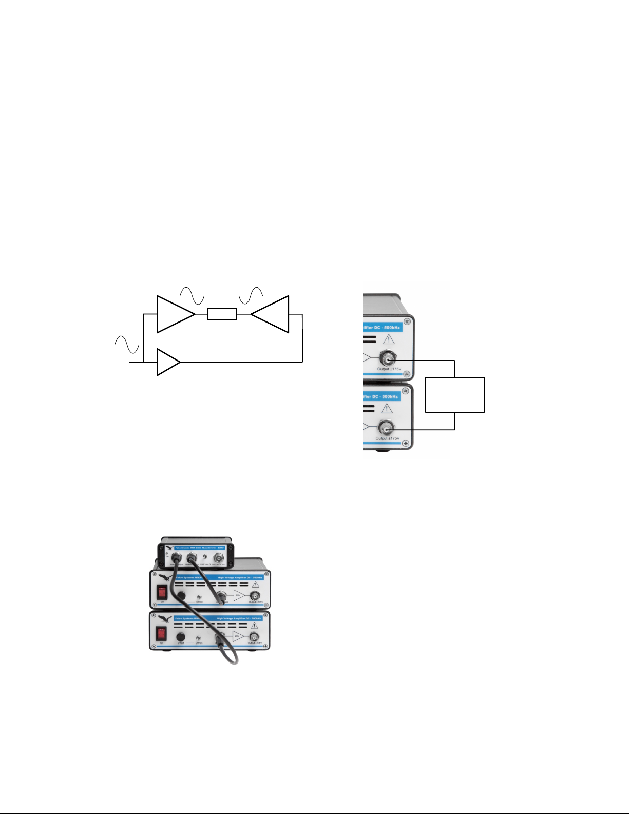
Figure 4. Shielded, differentially driven
load for bridge mode operation
The housing of the modulator is connected
to the shield of the cables this way,
resulting in good interference rejection.
This scheme is also the recommended
one if the user has the possibility to design
the connections of the load him/herself.
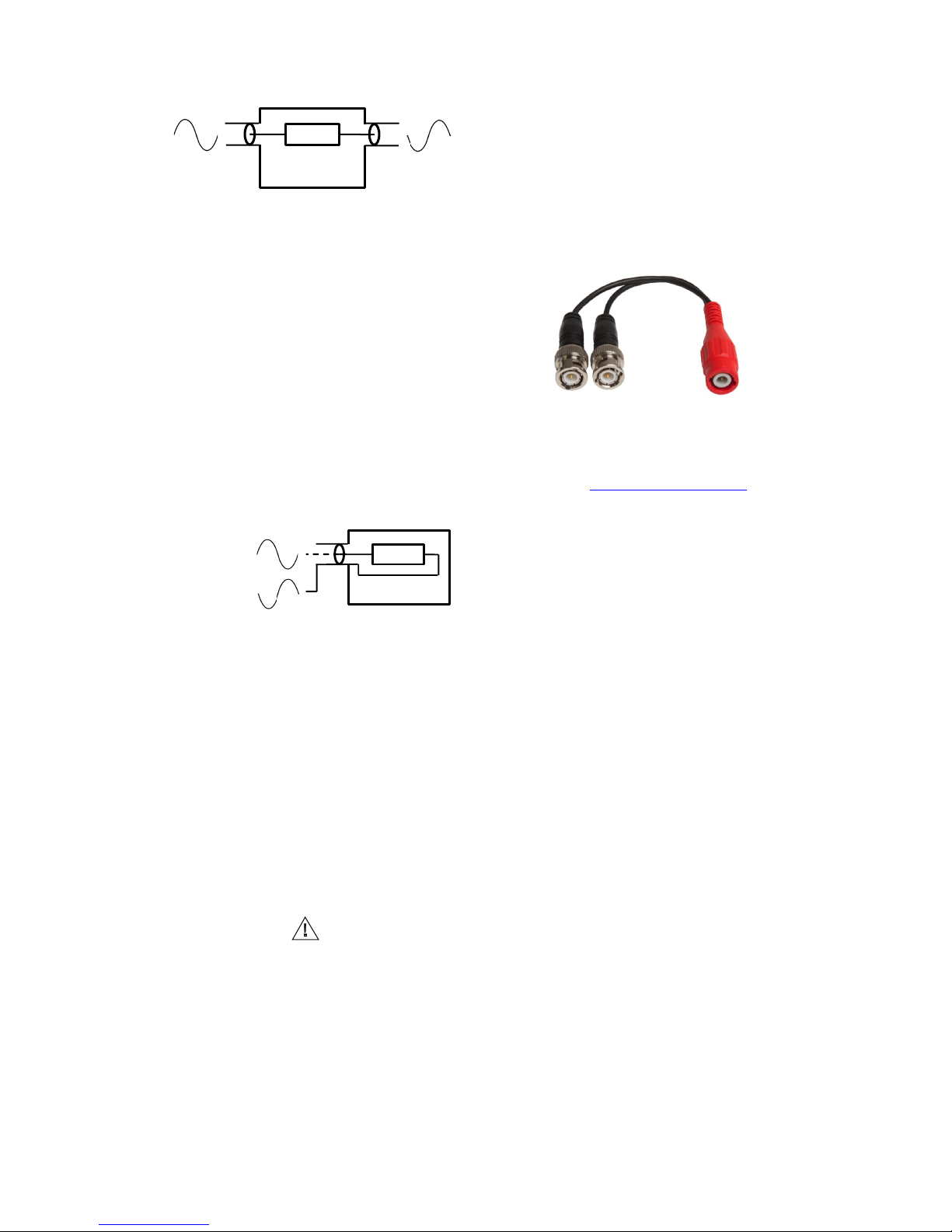
In situations where driving the load
differentially with two connectors is
impossible, e.g. because the load has only
a single connector, both amplifier outputs
have to be connected together at the load,
as depicted in Fig. 5.
Figure 5. Driving a single-connector load
in bridge mode
If one of the two connections of the
connector is connected to the (conductive)
housing of the load, check that:
!the housing/outside of the load floats
with respect to the ground of the
amplifiers, i.e. it makes no contact with the
electrical circuit to which the amplifiers
belong, other than via the output cables,
and
!the housing/outside of the load and the
BNC connector itself cannot be touched,
as it carries the full output voltage of one
of the high voltage amplifiers. For this
reason the sign is present on the
enclosure. The use of an insulated BNC
connector is recommended.
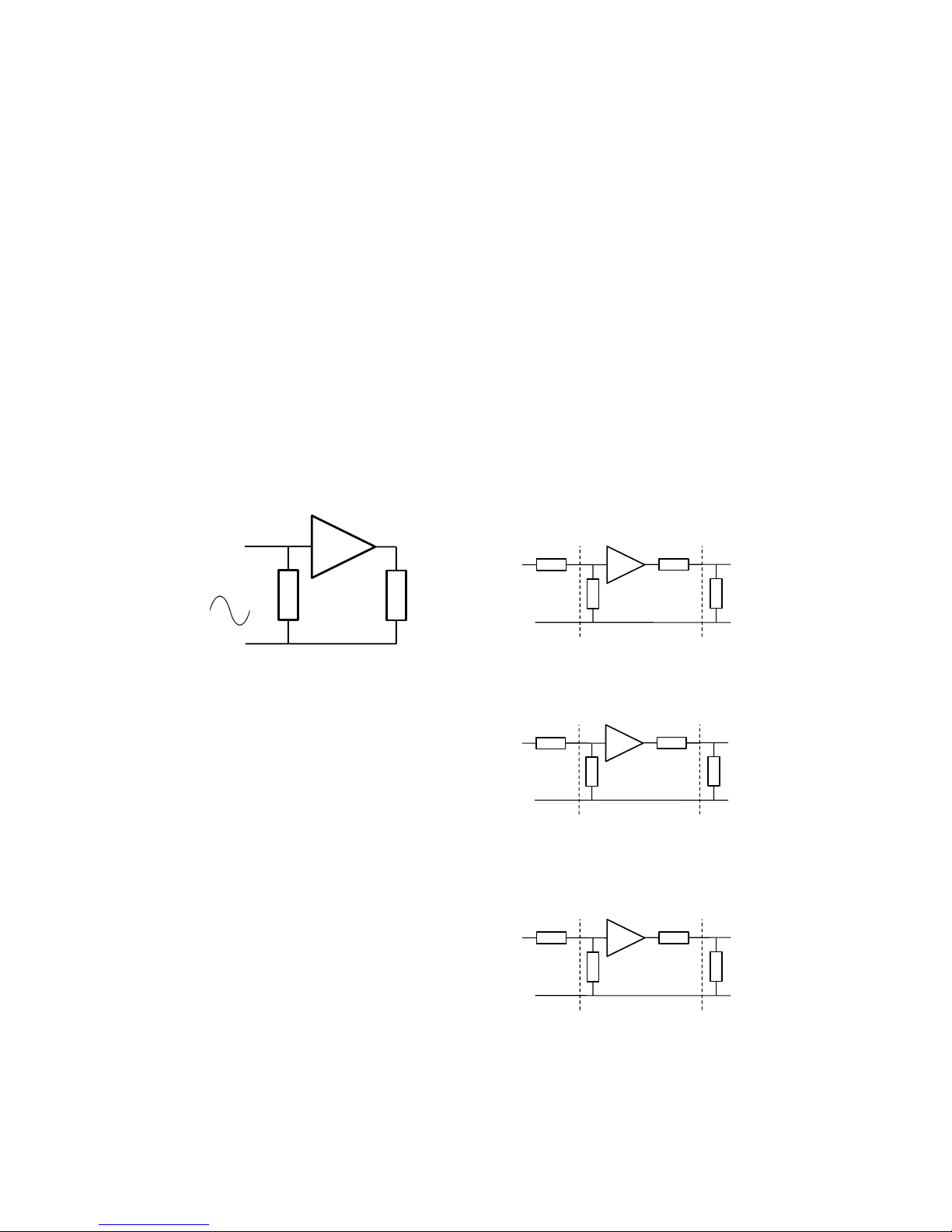
To aid in connecting floating loads in
bridge mode, Falco Systems offers a
special ‘bridge mode insulated tee-cable’
(Fig. 6). This cable takes the two amplifier
cables on BNC connectors, and has a
third BNC connector, where the inner
conductor of one input cable is connected
to the inner pin, and the inner conductor of
the other cable to the outer ring, which is
normally associated with the 0V shield.
This functionality is very different from a
normal BNC tee-adapter, which is only
used to connect the inner conductor of a
BNC cable to two cables, with all inner
pins connected together.
Figure 6. A ‘bridge mode’ tee-cable for
connecting the load is available from Falco
Systems, and can be purchased on the
website www.falco-systems.com
Required amplifier properties
The WMA-IB-HS phase inverter - buffer
can be used with many high voltage
amplifiers, and is not limited to driving
amplifiers of the Falco Systems brand.
Most amplifiers with an output current
limiter are suitable, as the current limiter
will ensure that the maximum power
dissipation inside the amplifier will not be
exceeded. When the setup is used with
fast changing signals, the voltage and
current transients at the amplifier outputs
may be slightly different in bridge mode
than when the load is grounded. For most
amplifiers this will be no problem, but
when in doubt, please contact the
manufacturer of the high voltage amplifiers
before using the amplifiers in bridge mode.
Amplifiers without a current limiter will
dissipate twice the normal power. The
double voltage will be shared equally
between the amplifiers in bridge mode, but
the doubled voltage across the load will
result in a doubled current, which flows
through both amplifiers. Depending on the
details of the setup, this higher dissipation
may or may not be a problem. Again,
when in doubt, please contact the
manufacturer of the amplifiers before
using the amplifiers in bridge mode.
Load
Cable 1 Cable 2
Shielding enclosure
Load
Cable inner
conductor
Enclosure
Cable outer
shield
Cable

Buffer mode
Although primarily intended for driving high
voltage amplifiers in bridge mode, the
WMA-IB-HS can also be used as a stand-
alone buffer to connect low power signal
sources to equipment with a 50Ωinput
impedance. Please note that computer-
controlled setups with DAQ (data
acquisition) cards often are not able to
drive a 50Ωhigh voltage amplifier input
directly. This is caused by the very limited
current capability of the outputs of typical
DAQ cards, which is insufficient to drive a
50Ωinput.
An example is driving the input of a Falco
Systems WMA-300 high-speed high
voltage amplifier from a DAQ card. This
will result in a highly distorted and clipped
signal coming out of the DAQ card at
higher output voltages.
The solution is to use a WMA-IB-HS as
the buffer between the low current signal
source and the 50Ωequipment (Fig. 7).
Figure 7. Using the WMA-IB-HS as a
buffer with a high input impedance to drive
a 50Ωimpedance
The input of the WMA-IB-HS is set to the
high impedance 100kΩsetting not to load
the signal source unduly, and its ‘buffered
out’ will drive 50Ωequipment without any
problems. If the signal coming from the
source is fast-changing, such as a square
wave or high frequency sine wave, then
mount the WMA-IB-HS very close to the
signal source. This is done to prevent
reflections in the non-50Ωconnection
between the signal source and the WMA-
IB-HS buffer input.
50Ω: preserving signal
amplitude
The WMA-IB-HS is equipped with both a
50Ωand a 100kΩinput. A typical 50Ω
source such as a function or arbitrary
waveform generator has a 50Ωoutput and
will form a 1:2 voltage divider with the 50Ω
input resistance of the WMA-IB-HS. To
prevent the loss in signal amplitude due to
this voltage divider, the WMA-IB-HS
amplifies the signal at its input by a factor
2 when the input is switched to the 50Ω
setting. The factor 2 ensures that the
signal at the output has the same
amplitude when driven from a 50Ωsource,
irrespective of whether the input is set to
50Ωor 100kΩ.
If the signal source has a very low output
resistance and drives the 50Ωinput, the
voltage gain is 2x, because the 1:2 voltage
divider is absent. When the WMA-IB-HS
drives a high impedance load such as an
amplifier input, the voltage at the output
will be the same as the voltage at the
input. If the output drives a 50Ωinput, the
voltage divider consisting of the 50Ω
output resistance of the WMA-IB-HS and
the 50Ωinput of the amplifier will divide
the signal available at the high voltage
amplifier input by a factor 2. This is just
what a 50Ωsignal source such as a
function generator would do. Fig. 8
illustrates the gain of the WMA-IB-HS for
different situations.
Figure 8a. 50Ωgenerator, 100kΩinput,
high impedance load; Vout = Vin
Figure 8b. 50Ωgenerator, 100kΩinput,
50Ωload; Vout = Vin/2 (this also happens
without the WMA-IB-HS present, with only
the amplifier input loading the generator)
Figure 8c. 50Ωgenerator, 50Ωinput, high
impedance load; Vout = Vin
Current
limited Vin
Buffer
100kΩ50Ω
Vin 1x
100kΩ100kΩ
50Ω
Vout = Vin
50Ω
Generator WMA-IB-HS Amplifier input
Vin 1x
100kΩ50Ω
50Ω
Vout = Vin/2
50Ω
Generator WMA-IB-HS Amplifier input
Vin 2x
50Ω100kΩ
50Ω
Vout = Vin
50Ω
Generator WMA-IB-HS Amplifier input

Figure 8d. 50Ωgenerator, 50Ωinput, 50Ω
load; Vout = Vin/2
Figure 8e. 0Ωgenerator, 50Ωinput, 50Ω
load; Vout = Vin
Figure 8f. 0Ωgenerator, 100kΩinput, high
impedance load; Vout = Vin
Figure 8g. 0Ωgenerator, 50Ωinput, high
impedance load; Vout = 2·Vin
Figure 8. The gain structure of the WMA-
IB-HS under different conditions
More information about 50Ωsystems can
be found online in the Falco Systems
application note “High voltage amplifiers
and the ubiquitous 50 Ohm: caveats and
benefits” at:
www.falco-systems.com/applications.html
Recommendations and safety
Recommendations:
!Heed the advice in the ‘connecting the
load’ section of the manual. In short: do
not short circuit one of the amplifiers by
grounding the load, and make sure the
voltage-carrying parts of the load cannot
be touched during operation.
!Never apply more than +10V (or less
than -10V) to the phase inverter/buffer
input to prevent damage.
!The phase inverter/buffer cannot be
damaged by a short-circuit condition or
capacitive loading, but avoid:
- Connecting a charged capacitor to the
input or output.
- Connecting a highly inductive load to
the output (such as a coil).
!Do not connect anything to the phase
inverter - buffer that can act as an
antenna.
!This product should only be cleaned with
a soft, slightly moist cloth. Disconnect the
phase inverter/buffer from the power
supply and all equipment before cleaning.
Safety:
!The WMA-IB-HS high speed phase
inverter - buffer is only suitable for indoor
use in a class II environment (domestic,
light industrial).
!Only use the power supply adapter
supplied by Falco Systems: Mean Well
GS25B28-P1J, 100-240V~ 50/60Hz in,
28V 25W DC out, with custom MiniDIN
connector.
!Only replace fuses with the correct type:
5x20mm 315mAT 230V fuse on the rear
panel.
!This product cannot be powered by non-
sinusoidal mains power generators.
!Only replace a damaged power cord with
an equivalent type: H03VVH2-F 2X 0,75
mm2, with Euro to C7 equipment
connector.
!The airflow to and from the WMA-IB-HS
should not be blocked or impeded, to allow
for adequate ventilation.
Transmitter mode
This high speed phase inverter - buffer
can generate a significant amount of
power at frequencies used for radio
transmission and reception. It should not
be used for telecommunication as
described in the R&TTE directive 95/5/EC.
Always use coaxial cables.
Vin 2x
50Ω50Ω
50Ω
Vout = Vin/2
50Ω
Generator WMA-IB-HS Amplifier input
Vin 2x
50Ω50Ω
0Ω
Vout = Vin
50Ω
Generator WMA-IB-HS Amplifier input
Vin 1x
100kΩ50Ω
0Ω
Vout = Vin
50Ω
Generator WMA-IB-HS Amplifier input
Vin 2x
50Ω100kΩ
0Ω
Vout = 2·"Vin
50Ω
Generator WMA-IB-HS Amplifier input

WMA-IB-HS phase inverter - buffer characteristics
9a. Input signal (divided by 2 due to the 50Ωloading of the 50Ωoutput of the generator by the
50Ωinput of the WMA-IB-HS)
9b. Buffered output signal: signal amplitude is restored by the 2x gain of the WMA-IB-HS
9c. Corresponding inverted output signal
Figure 9. 1MHz 20Vpp square wave output signal at the buffered and inverted outputs (50Ω
input impedance setting, function generator with 50Ωoutput)
Time%(μs)%
Amplitude%(V)%
-6
-4
-2
0
2
4
6
2.52.01.51.00.50.0
Time%(μs)%
Amplitude%(V)%
-10
-5
0
5
10
2.52.01.51.00.50.0
Time%(μs)%
Amplitude%(V)%
-10
-5
0
5
10
2.52.01.51.00.50.0

Figure 10. Bandwidth at 3Vpp into a 50Ωload with the input switched to 50Ωand 100kΩinput
impedance (the 100kΩresponse depends on type of source and input cable properties)
11a. Noise at the buffered output
11b. Noise at the inverted output
Figure 11. Output noise (AC coupled) with a 50Ωshielded BNC dummy load on the input,
with the input switched to 50Ωimpedance
!"#$%#&'()*+,-)
./0&)
1.2
1.0
0.8
0.6
0.4
0.2
0.0
103104105106107108
50 Ohm input
100k input
Time%(ms)%
Output%noise%(μV)%
800
600
400
200
0
-200
-400
-600
100806040200
Time%(ms)%
Output%noise%(μV)%
800
600
400
200
0
-200
-400
-600
-800
100806040200

Technical specifications
Input: 50Ωor 100kΩinput impedance, switchable, ±10V max input voltage
Output: 50Ωoutput impedance, ±10V max out in a high impedance load, ±5V max out in a
50Ωload
Gain: buffered out: +1x, inverted out: -1x, independent of the input impedance switch setting.
Gain changes automatically
Bandwidth DC – 20MHz @-3dB typical at either output, when input and outputs are used
with 50Ωequipment
Noise and offset: buffered out: ~125µVrms noise, Inverted out: ~160µVrms noise (all values
typical, in DC – 100MHz measurement bandwidth); typical offset of both outputs ~0.9mV with
50Ωinput setting, ~3.3mV with 100kΩsetting
Delay time: input to buffered out: 12 ns typical, buffered out to inverted out: 9 ns typical
Operating temperature: 15 – 30°C
Storage temperature: 0 – 60°C
Relative humidity: 30 – 70% non-condensing
Maximum usage height: 2000m
Dimensions and weight: 190x106x40mm, 0.4 kg
Power: 28V DC, 200mA maximum, with 315mAT 5x20mm 230V fuse and on/off switch on
rear panel. Use the power supply adapter supplied by Falco Systems only: Mean Well
GS25B28-P1J, 100-240V~ 50/60Hz in, 28V 0.75A DC out, 25W, with custom MiniDIN
connector
Country of origin: The Netherlands
Specifications may be subject to change
Harmonized standards
This product complies with the following
standards:
Safety: EN61010-1
EMC: EN61326
FCC: 47 CFR 15
The mark is present on the WMA-IB-
HS to indicate compliance of this
equipment with the European Union safety
and EMC regulations, while the mark
has been added to indicate compliance
with the United States FCC regulations.
WEEE and RoHS
Do not dispose of the WMA-IB-HS phase
inverter – buffer as standard waste, but
bring it to a WEEE electronic waste
collection point. This is indicated by the
sign on the WMA-IB-HS. The WMA-
IB-HS has been built in compliance with
the RoHS directive.
Warranty
Falco Systems products are guaranteed
against malfunction due to defects in
materials or workmanship for a period of 1
year from the date of shipment.
If a malfunction occurs during this period,
the product will be repaired or replaced
without charge. The product will be
returned to the customer prepaid.
The warranty does not apply to:
!Exterior finish or appearance
!Malfunction resulting from use or
operation of the product in other ways than
specified in the user manual
!Malfunctioning due to misuse or abuse of
the product
!Malfunctioning occurring after changes
or repairs have been made by anyone
other than Falco Systems.
To obtain warranty service, the customer
has to inform Falco Systems first via
info@falco-systems.com to receive further
instructions.
Falco Systems will not be liable for any
consequential damages, including, without
limitation, devices or equipment connected
to the product, injury to persons or
property or loss of use. See for more
details the Falco Systems Standard Terms
and Conditions of Sale, which can also be
obtained via info@falco-systems.com.

User manual version
User manual version: 1.5
Date: October 29, 2018
Falco Systems
Falco Systems
Remisestraat 1
2225 TH Katwijk aan Zee
The Netherlands
Tel. +31 (0)6 21840996
Fax. +31 (0)20 2031445
Email: info@falco-systems.com
www.falco-systems.com
Table of contents
Other Falco Systems Inverter manuals