NHRC NHRC-4 User manual

NHRC-4
Installation and
Setup Guide
Hardware Version: Rev. D.
Guide Version: 2005-Nov-07

Copyright Notice
Copyright 1999, 2005, by NHRC LLC
This document contains proprietary information, which is the confidential property of
NHRC LLC.
No part of this document may be used or reproduced, by any means, or for any purpose,
without the expressed written consent of NHRC LLC.
No part of this document should be considered to be specifications for the proper or
correct operation of the NHRC-4 Repeater Controller. In no way will NHRC LLC be
liable for direct or indirect damages to the controller or attached equipment.
Printed in the U.S.A.

Thank You!
Thank you for purchasing the NHRC-4 Repeater Controller. This controller has been
designed using the very latest state-of-the-art technology. Please review this manual
carefully before putting your controller into operation.
This manual represents a very large documentation effort. Your comments are
important to us. If you find an error or find any passages that are not clearly
understandable we would like to hear about it. Please send your comments to
Support for the controller is available by email or telephone. Please direct software-
answered promptly.
Questions of a more urgent nature can be answered by telephone support. Telephone
support is available Monday through Friday, from 6 PM until 9:30 PM, Eastern Time.


Table Of Contents
1. INTRODUCTION ................................................................................................................................2
2. INSTALLATION..................................................................................................................................2
2.1 PRIMARY RADIO PORT CONNECTIONS ............................................................................................2
2.2 SECONDARY RADIO PORT WIRING..................................................................................................4
2.3 TS-32/TS-64 HOOKUP ....................................................................................................................5
2.3.1 TS-64 Notes ...............................................................................................................................5
2.3.2 TS-32 Notes ...............................................................................................................................6
2.4 USING A NHRC-DAD WITH THE NHRC-4.....................................................................................6
2.5 USING THE DIGITAL OUTPUT ..........................................................................................................6
2.6 THE LED STATUS INDICATORS.......................................................................................................7
2.7 ADJUSTING THE AUDIO LEVELS......................................................................................................7
3. APPENDICES.......................................................................................................................................9
3.1 TERMINOLOGY AND ABBREVIATIONS .............................................................................................9
4. CIRCUIT BOARD .............................................................................................................................10
4.1 INTERCONNECTIONS .....................................................................................................................10
4.2 BOARD LAYOUT ...........................................................................................................................11
5. SCHEMATICS ...................................................................................................................................12
PARTS LIST................................................................................................................................................14
PARTS LIST................................................................................................................................................15
NHRC LLC LIMITED WARRANTY ......................................................................................................16
Copyright 2001, 2005, NHRC LLC. All Rights Reserved. Page i

NHRC-4 User Guide
1. Introduction
This manual describes how to install and set up the NHRC-4 repeater controller. This manual
should be used in conjunction with the NHRC-4 Operating Manual, which describes the
programming and operation of the controller.
2. Installation
This section of the User Guide describes the electrical interfaces used to connect the
controller to:
• Power and primary repeater
• Link/Remote Base radio
• Communications Specialists TS-64 CTCSS Encoder/Decoder
• Optional NHRC-DAD digital audio delay board(s).
It is intended for the repeater operator to use in the planning and installation of the NHRC-4
Repeater Controller into a repeater system.
The controller uses a 8 pin 0.100" header for all the primary radio's signals and DC power, a
6 pin 0.100" header for the secondary radio's signals, and a 6 pin 0.100" header for an
external TS-64 CTCSS encoder/decoder for the primary radio. In addition, it has two 4 pin
0.100" connectors to support optional NHRC-DAD digital audio delays for both radio ports.
Each radio port requires audio and a signal present indication (CAS) from it's receiver, and
supplies transmit audio and PTT to it's transmitter. The controller requires 13.8 volts DC for
power, which is provided on the primary radio's connector.. Be very careful when wiring DC
power to the controller, reverse polarity will severely damage the controller. The connector
pinouts are shown in the tables below.
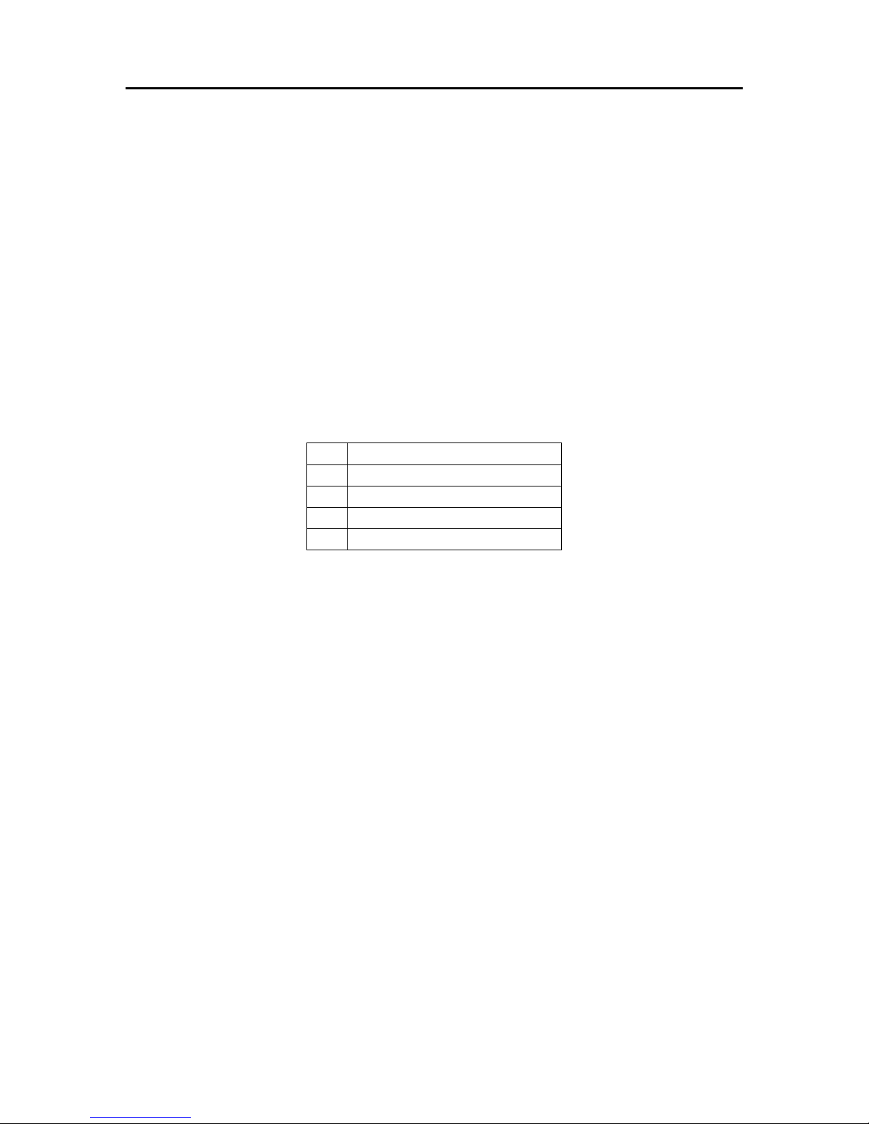
2.1 Primary Radio Port Connections
The J1 connector contains the power and radio interface signals for the “Primary” radio port.
J1 Primary Radio Port (“Repeater”) Connections
J1
Pin # Use
1 +13.8 Volts
2 CAS (active high)
3 PTT (active low)
4 Receiver Audio
5 Transmitter Audio
6 Fan/Digital output (active
low)
7 Ground/Audio Return
8 Ground/Audio Return
Page 2 Copyright 2001, 2005, NHRC LLC. All Rights Reserved.

NHRC-4 User Guide
Receiver audio can typically be taken from the high side of the squelch control. This audio
must be de-emphasized with the controller's de-emphasis circuit, which provides a -
6dB/octave slope. Optionally, audio can be taken from later in the receiver's audio chain,
where it is already de-emphasized. Care must be taken that this source of audio is not subject
to adjustment by the radio's volume control. If the receiver audio has not been properly de-
emphasized, either in the receiver itself or on the controller board, the repeater will have a
very "tinny", unnatural sound to it. The NHRC-4 repeater controller is shipped without the
de-emphasis circuit populated on the printed circuit board, for "flat" audio response. To
install the de-emphasis filter, two 100K ohm resistors must be removed, and a 51K ohm, a
510K ohm, and a 6800pF capacitor must be installed on the board. Consult the NHRC-4
Repeater Controller (Audio) schematic for modification instructions.
The receiver must provide a signal present indication (also called CAS, COR, RUS) to the
controller. The controller requires an "active-high" signal here. If your radio only has
"active-low" signaling available, a simple inverter can be constructed with a 2N3906 and a
4.7K resistor. Connect the emitter of the transistor to a source of positive voltage, the
collector to the controller's CAS terminal, and the base to the active-low signal through the
4.7K resistor.
Transmitter audio can be fed directly into the microphone input of the transmitter. VR5 is
the master level control for the primary radio, used to set the audio level into the transmitter.
VR2 is the master level control for the secondary radio. The transmitter's deviation limiter
(sometimes called IDC) should be set such that the transmitter cannot overdeviate,
regardless of input signal level. One way to adjust transmitter deviation is to set the
transmitter deviation limiter wide open (unlimited), adjust the controller's master output until
the transmitter is slightly overdeviating, then set the transmitter's deviation limiter to limit
just below 5 KHz deviation. Then reduce the controller's master output until the transmitted
audio does not sound compressed or clipped. Transmitter deviation should be adjusted with
a service monitor or deviation meter.
Transmitter keying is provided by a power MOSFET (Q2/Q6) configured in an open-drain
circuit. This can be used to key many transmitters directly. The MOSFET essentially
provides a closure to ground for PTT. For other transmitters, the MOSFET can drive a small
relay to key the radio. Although this MOSFET can handle several amps, we recommend that
no more than 500 mA of current be drawn through it.
Copyright 2001, 2005, NHRC LLC. All Rights Reserved. Page 3

NHRC-4 User Guide
2.2 Secondary Radio Port Wiring
The J2 connector contains the radio interface signals for the “Secondary” radio.
J2 Secondary Radio Port Connections
J2
Pin # Use
1 CAS (active high)
2 PTT (active low)
3 CTCSS detect (active high)
4 Receiver audio
5 T transmitter audio
6 Ground
Page 4 Copyright 2001, 2005, NHRC LLC. All Rights Reserved.

NHRC-4 User Guide
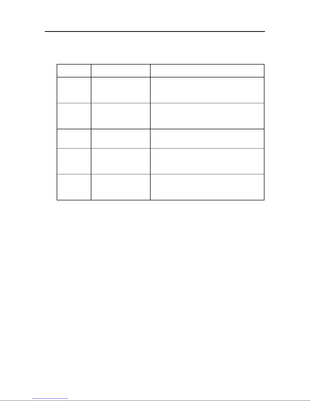
2.3 TS-32/TS-64 hookup
Connector J3 is a 6-pin header that allows the easy installation of an optional
Communications Specialists TS-32 or TS-64 for CTCSS decode, encode, CTCSS audio
filtering, and reverse-burst. (Reverse burst is only available with the TS-64.) Wire J3 to the
TS-32/TS-64 as follows:
J3 Connections
JTS64
Pin #
TS-32
Signal Description
1 +V Power +10 volts to CTCSS board
2 CTCSS decoder input Receiver audio to CTCSS decoder
3 To audio filter input Receiver audio to audio filter input
(separate lead for TS-64)
4 From audio filter output Filtered audio to controller
5 CTCSS detect Decode signal from CTCSS decoder
See important warning below!
6 Ground and “Hang Up” Ground
WARNING:
DO NOT APPLY VOLTAGE TO THE CTCSS DETECT INPUT!
This input is pulled low by the CTCSS decoder when CTCSS is NOT PRESENT. It will float high
when CTCSS is detected. Application of voltage to this input will render the controller
inoperative. Damage of this nature is not covered by the NHRC Limited Warranty.
The TS-32 and the TS-64 both have a high-pass filter to remove the CTCSS tone from the
repeated audio. By removing jumper JP1, the controller's audio can be passed through the
audio filter on the TS-32/TS-64.
Note: If the audio filter is not used, then jumper JP1 must be installed in order for audio to
be passed through the controller.
The Communications Specialists CTCSS boards are not supplied by NHRC. Contact
Communications Specialists at 800-854-0547 directly to order these boards.
2.3.1 TS-64 Notes
Consult the NHRC-4 TS-64 Application note for detailed connection instructions.
The TS-64 has a reverse-burst/PTT delay feature that can be used with the NHRC-4 with
some additional wiring. This feature is useful to eliminate the squelch crash received by the
user's radio when the repeater transmitter drops. Note that the user's radios must have
CTCSS decoding enabled for this to work. The PTT signal from the NHRC-4 must be routed
through the TS-64, and the TS-64 encoder output must be wired to the transmitter’s CTCSS
input.
Copyright 2001, 2005, NHRC LLC. All Rights Reserved. Page 5
NHRC-4 User Guide
Consult the TS-64 INSTRUCTION SHEET for details on setting the CTCSS frequency and
the reverse burst.
2.3.2 TS-32 Notes
The TS-32 must have the JU-2 jumper cut. Use the OUT-2 signal from the TS-32 into the
CTCSS detect of the NHRC-4. If you want to be able to disable the CTCSS requirement,
install a switch on the HANGUP lead.
Consult the TS-32 INSTRUCTION SHEET for details on setting the CTCSS frequency.
2.4 Using a NHRC-DAD with the NHRC-4
The NHRC-4 supports the NHRC-DAD digital audio delay on both the primary and
secondary radio ports. The NHRC-DAD is used to reduce or eliminate squelch crashes and
to allow the controller to fully mute DTMF tones.
J4 Primary Radio DAD Connector
J4 Secondary Radio DAD Connector
Pin Use
1 +13.8 Volts to delay board
2 Audio to delay board
3 Audio from delay board
4 Ground/Audio Return
The audio delay for the primary radio simply plugs in to J4. The audio delay for the
secondary radio plugs in to J5. If the audio delay is not installed, a jumper between pins 2
and 3 of the port's delay connector must be installed, or the controller will not pass audio.
It is strongly recommended that the CTCSS filter be used, as described above, if both
CTCSS encode/decode and the audio delay are used.
The repeater controller needs to “know” that the delay is present in order to adjust the CAS
timing requirements to fully mute squelch crashes. Consult the NHRC-4 User Guide for
further information on programming the controller to indicate that the delay is present.
2.5 Using the Digital Output
The NHRC-4 Repeater Controller has a digital output that can be used for various remote
control applications or to control a fan on the repeater's transmitter. The digital output is an
open-drain into a power MOSFET, which is capable of sinking quite a bit of current, but we
recommend a maximum load of about 500 mA. Use a relay to drive larger loads. The open-
drain output can be used to gate the HOOKSWITCH signal to a TS-32 or other CTCSS
decoder. Software allows the output to be enabled, disabled, or pulsed. In fan control mode,
this output will be turned on when the transmitter is turned on, and turned off a
programmable amount of time after the transmitter is turned off. Consult the NHRC-4 User
Guide for information about how to control the digital output.
Page 6 Copyright 2001, 2005, NHRC LLC. All Rights Reserved.

NHRC-4 User Guide
2.6 The LED Status Indicators
The NHRC-4 repeater controller is equipped with five status LEDS that aid in setup and
troubleshooting. There are green LEDs for each radio port that indicate that the controller
has getting a valid CAS (carrier operated switch) and, if a CTCSS decoder is connected, a a
valid CTCSS decode signal. The appropriate green LED should light when its receiver is
active, and, if a CTCSS decoder is present, the correct CTCSS tone is present. The yellow
LED indicates that a DTMF signal is being decoded on the primary receiver. This LED
should light for the entire duration that the DTMF signal is present on the primary receiver.
The red LED's indicates transmit. These LED will light when its respective transmitter is
transmitting.
The LEDS can be disabled to reduce the power consumption of the controller. Remove
jumper JP2 to disable the LEDs.
2.7 Adjusting the Audio Levels
Audio Level Adjustments
Potentiometer Use
VR1 Secondary Receiver Mix Level
VR2 Secondary Transmitter Master Level
VR3 Primary Receiver Mix Level
VR4 Primary Receiver Level
VR5 Primary Transmitter Master Level
VR6 Beep Tone Mix Level
Preset all potentiometers to midrange. Key a radio on the primary input frequency, send
some touch-tones, and adjust VR1 (the primary receiver level) until DTMF decoding is
reliably indicated by yellow LED D5.
Note: If VR4 is set too high, a crackling noise may be heard in the transmitted audio during
the hang time. Reduce the level set by VR4 until this noise goes away. Any repeated audio
level reduction caused by adjusting VR4 can be compensated for by adjusting VR3 (primary
receiver mix level) or VR5 (primary transmitter master level.)
The primary radio's transmit deviation is set with VR5 (the primary transmitter master level)
on the controller board and the transmitter's deviation/modulation control. The key to
properly adjusting these controls is to remember that the limiter in the transmitter is after
VR5 but probably before the transmitter's deviation/modulation control. The transmitter's
deviation/modulation control will set the actual peak deviation, and VR5 will set the level
into the transmitter. You do not want excessive limiting on normal speech going through the
repeater; it sounds bad and tends to "pump-up" background noise. On the other hand, some
limiting is desirable. An oscilloscope connected to the audio output of a receiver tuned to the
transmitter's frequency will show limiting as the audio gets "flat-topped" or clipped by the
limiter. Ideally, a 4.5KHz deviation signal input to the repeater should result in a 4.5 KHz
deviation output, and 5.5 KHz of input deviation should result in just under 5.0 KHz of
deviation out of the repeater. A service monitor (or two), deviation meter, and/or a signal
generator are necessary to do this job right.
Copyright 2001, 2005, NHRC LLC. All Rights Reserved. Page 7

NHRC-4 User Guide
The secondary radio's transmit deviation is set with VR2 (the secondary transmitter master
level). Enable the secondary transmitter, and adjust VR2 for proper transmit deviation,
similarly to VR5.
Enable the secondary receiver, and adjust VR1 for reasonable deviation on the enabled
transmitters when a signal is received on the secondary receiver.
Adjust VR6 (the beep level) to set the courtesy tone and CW tone level.
VR3 is used to set the primary receiver's audio mix level, and may not need to be adjusted
from midpoint.
Page 8 Copyright 2001, 2005, NHRC LLC. All Rights Reserved.

NHRC-4 User Guide
3. Appendices
3.1 Terminology and Abbreviations
Term Description
CAS Carrier Activated Squelch, where receipt of a signal,
with or without CTCSS tones will activate the
controller.
CW Continuous Wave signals, commonly using “Morse
Code.” The term “CW” refers to the radio emission
type, while “Morse Code” refers to the signaling type
used. Typically, they are incorrectly used
interchangeably.
Digital Audio Delay (DAD) Digital Audio Delay (DAD) removes squelch crashes
and allows DTMF tones to be fully muted.
DTMF Also known as “Touch Tone” codes.
ID Identification
PTT Push-to-Talk
Copyright 2001, 2005, NHRC LLC. All Rights Reserved. Page 9
NHRC-4 User Guide
4. Circuit Board
4.1 Interconnections
Connector Name Purpose
J1 “REPEATER” Connects the primary repeater transmit and
receive audio, PTT, CAS, fan control, and
power signals to the controller.
J2 “REMOTE BASE” Connects the secondary repeater transmit and
receive audio, PTT, and CAS signals for the
radio to the controller.
J3 “TS-32/64” Interfaces a Communications Specialists TS-64
to the controller for CTCSS detection.
J4 “DELAY” Connects power and audio signals for operation
of the Digital Audio Delay (NHRC-DAD) board
for the primary radio port.
J5 “RB DELAY” Connects power and audio signals for operation
of the Digital Audio Delay (NHRC-DAD) board
for the secondary radio port.
Page 10 Copyright 2001, 2005, NHRC LLC. All Rights Reserved.

NHRC-4 User Guide
4.2 Board Layout
This is a detailed top view of the Revision “D” printed wiring board for the NHRC-4
Repeater Controller.
NHRC-DAD
Interface Connectors
Main
Repeater
Remote
Base
CommSpec
TS-32/64
Interface
Connector
Remote
Base
Connector
Main
Repeater
Connector
CommSpec
TS-32/64
Audio Bypass
Jumper
LED Enable
Jumper
INIT Jumper
Copyright 2001, 2005, NHRC LLC. All Rights Reserved. Page 11

NHRC-4 User Guide
5. Schematics
The following two pages the schematic diagram for the Revision “C” Version of the NHRC-4
Repeater Controller.
Page 12 Copyright 2001, 2005, NHRC LLC. All Rights Reserved.

NHRC-4 User Guide
A
A
B
B
C
C
D
D
E
E
4 4
3 3
2 2
1 1
PIC uP
LE D ENAB L E
BYPASS C APS
COR LED
CAS/COR ISOL ATION
REMOTE BASE
COR LED
CAS/COR ISOL ATION
MAIN
PTT LED
PTT DRIVER
REMOTE BASE
REMOTE BASE
MAIN
REMOTE BASE
REMOTE BASE
CO NNECTOR
TS-32/64
CON NECT OR
REPEATER
CON NECT OR
PTT LE D
PTT DRIVER
MAIN
MAIN
DIGITAL (FAN) OUTPUT DRIVER
TS-32/64 FILTER BYPASS
NOTICE
THIS DRAW ING CONTAINS
PROPRIETARY INFORMATION WHICH
IS THE CONFIDENTIAL PROPERTY
COPIED, REPRODUCED, DISCLOSED,
PUBLISHED OR USED IN PART OR
WHOLE WITHOUT THE EXPRESSED
OF NHRC LLC. IT SHALL NOT BE
WRI TTEN PERMISSION OF NHRC LLC.
SPECIFICATIONS SUBJECT TO CHANGE
WITHOUT NOTICE OR OBLIGATION.
PCB REV D
1.) All resistors 1/4W 5% tol.
unless otherwise stated.
2.) All cap acito rs are 16 V
electrolytic / 50V ceramic unless
otherwise stated.
NOTES:
DTMF D ECO DER
STD LED
NHRC-4 (Digital) D1
NHRC-4 Repeater Controller (Digital)
415 Fourth Range Road
Pembroke, NH 03275
603-485-2248
B
12Wednesday, October 26, 2005
http://www.nhrc.net
Title
Size Do cum ent Num be r Re v
Date: S heet of
Q1
Q2
Q3
Q4
STD
PTT_EN
RB_COR
RB_PTT_EN
DOUT_EN
COR
PICCLK
PL _D EC
RB_CAS
RB_COR
RB_PL_DEC
CAS
COR
PL_D EC
RB_PTT
RB_PTT_EN
CAS
PTT
RX _A UDIO
RX_AUDIO
RB _P L_D E C
RB _C AS
RB_PTT
RX_AUDIO
RX_AUDIO
PTT _ EN
PTT
DOU T_EN
DOUT
DOU T
Q3
STD
Q4
Q2
PIC CL K
Q1
DISC_AUDIO
DISC_AUDIO
TX_ A UDIO
RB_TX_AUDIO
RB _DIS C_ A UDIO
MUTE
RB_MUTE
BEEP
DECODE_AUDIO
+12V
+5V
+12V
+12V
+5V
+5V
+12V
+12V
+5V
+5V
VLED
+5V
VLED
+5V
VLED
+5V
VLED VLED
+5V
VLE D
+5V
Q3
2N3904
1
2
3
J3
HEADER 6
1
2
3
4
5
6
R10
100
1 2
D1
LE D R ED
12
R3
10K
12
Q2
IR F5 1 0
1
23
R9
470
12
R28
470K
12
R34
100K
1 2
C22
100pF
1 2
C19
0.1uF
12
C20
0.1uF
12
R4
100
1 2
R36
10K
12
R24
470
12
+C15
220uF
25V
12
Y1
3.579MHz
1 2
Q1
IRF510
1
23
Q6
IRF510
1
23
D4
LED GRN
12
R19
100
1 2
R33
10K
12
+C21
1uF
12
+C18
1uF
12
R26
10K
1 2
R27
470
12
U4
PIC16F628-04/P
17
18
1
2
6
7
8
9
10
11
12
13
14
5
3
15
16
4
RA0
RA1
RA2
RA3
INT/RB0
RB1
RB2
RB3
RB4
RB5
RB6
RB7
VDD
VS S
TOCKI/R A4
OSC2/CLKO
OSC1/CLKI
MCLR/VP P
R30
10K
1 2
Q10
2N7000
2
31
D3
LED RED
12
Q9
2N3904
1
2
3
D5
LED YEL
12
J1
HEADER 8
1
2
3
4
5
6
7
8
R31
470
12
Q8
2N3904
1
2
3
D2
LED GRN
12
R2
10K
12
JP2
JUMPER
1 2
R29
10K
12
C16
0.1uF
12
R1
10K
1 2
U3
MT8870
18
98
7
1
2
4
3
11
12
13
14
16
15
1710
5
6
VDD
VSSOSC2
OSC1
IN+
IN-
VREF
GS
Q1
Q2
Q3
Q4
EST
STD
ST/GTOE
IC
IC
R16
470
12
U2
LM7805CT
1 3
2
IN OUT
GND
JP1
JUMPER
1 2
Q5
2N3904
1
2
3
J2
HEADER 6
1
2
3
4
5
6
Copyright 2001, 2005, NHRC LLC. All Rights Reserved. Page 13

NHRC-4 User Guide
A
A
B
B
C
C
D
D
E
E
4 4
3 3
2 2
1 1
FO R DE EMP HAS I ZED
AUDIO RESPONSE:
INSTALL C11 AND
CHANG E R 20 TO 510K.
RX AUDIO
AUDI O MUTE
VREF GENERATION
BUFFER
MAIN
LE VE L
INIT
NOTE:
MASTER LEVEL
REMOTE BASE
RX AUDIO
BUFFER
RE MOT E BA S E
LE VE L
REMOTE BAS E
MAIN
MAIN R X
AUD IO MUTE
RE MOT E B AS E RX
REMOTE BASE TX AUDIO
NOTE:
MAIN RX AUDIO
DELAY CONNECTOR
MAIN RX
AUDIO LEVEL
AUDIO LEVEL
COU RTESY T ONE
MAIN
MASTER LEVEL
MAIN TX A UDIO
CON NEC TOR
RX AUDIO DELAY
RE MOT E BA SE
TX AUDIO AMP
TX AUDIO AMP
RX AUD IO
RX A UD IO
NOTICE
THIS DRAWING CONTAINS
PROPRIETARY INFORMATION WHICH
IS THE CONFIDENTIAL PROPERTY
COPIED, REPRODUCED, DISCLOSED,
PUBLISHED OR USED IN PART OR
WHOLE W ITHOUT THE EXPRESSED
OF NHRC LLC. IT SHALL NOT BE
W RI TTEN PE RMIS SION O F NHRC LLC .
SPECIFICATIONS SUBJECT TO CHANGE
WITHOUT NOTICE OR OBL IGATION.
PCB REV D
1.) All resistors 1/4W 5% tol.
unles s o therwis e s tated .
2.) All capacitors are 16V
electrolytic / 50V ceramic unless
otherwise stated.
NOT ES:
FO R DE EMP HAS I ZED
AUDIO RESPONSE:
INSTA LL C4 AND
CHANG E R5 T O 510K.
NHRC -4 (Audio) D1
NHRC-4 Repeater Controller (Audio)
415 Fourth Range Road
Pembroke, NH 03275
60 3-485-2248
B
22Wednesday, October 26, 2005
http: //www.nhrc .net
Title
Size Document Number Rev
Date: Sheet of
DECODE_AUDIO
TX_AUDIO
RB_TX_AUDIO
MUTE
DISC_AUDIO
RB_DISC_AUDIO
RB _MUTE
BEEP
+5V
+12 V
VREF
+12V
VREF
VREF
VREF
VREF
VREF
+12V
VREF
+12V
+12V
R6
100K
1 2
J5
HEA DER 4
1
2
3
4
Q13
2N7000
2
31
-
+U1D
TL064
13
12
14
R35
100K
1 2
R15
100K
12
R40
10K
12
R39
100K
1 2
R23
33K
1 2
R13
22K
1 2
R18
22K
1 2
R22
10K
12
R25
100K
1 2
C8
0.1uF
1 2
R11
22K
1 2
C14
0.1uF
12
VR3
10K POT
13
2
Q4
MPF1 02
3
1 2
R12
10K
12
R17
10K
12
+
C3
1uF
1 2
+
C10
1uF
1 2
VR6
10K POT
13
2
+C7
22uF
25V
12
VR5
500K POT
1 3
2
VR4
10K P O T
13
2
+
C12
1uF
12
+
C13
1uF
12
C17
0.1uF
1 2
JP3
JUMPER
12
C11
0.0068uF
1 2
R20
100K
1 2
R21
100K
1 2
+C5
1uF
12
Q12
2N7000
2
31
-
+U1A
TL064
2
3
1
411
-
+U1B
TL064
6
5
7
-
+U1C
TL064
9
10
8
R14
100K
12
R32
100K
1 2
R8
33K
1 2
R7
10K
12
Q7
MPF102
3
1 2
+
C6
1uF
1 2
+
C9
1uF
1 2
VR2
500K POT
1 3
2
VR1
10K P O T
13
2
+
C2
1uF
12
+
C1
1uF
12
C4
0.0068uF
1 2
J4
HEA DER 4
1
2
3
4
R5
100K
1 2
Page 14 Copyright 2001, 2005, NHRC LLC. All Rights Reserved.

NHRC-4 User Guide
Parts List
The following is the bill of materials for revision “D” of the NHRC-4 Repeater Controller.
Item Qty Reference Part Description Populate Manufacture
r
Manufacturer P/N Digi-Key P/N
1 11 C1,C2,C3,C5,C6,C9,C10, 1uF 1.0uF 25V Tantalum Capacitor YES Kemet T350A105K025AS 399-1412-ND
C12,C13,C18,C21
2 2 C11,C4 0.0068uF 0.0068uF 50V X7R Ceramic Radial Cap NO Panasonic ECU-S1H682KBA P4951-ND
3 1 C7 22uF 22uF 25V Aluminum Radial Electrolytic Cap YES Panasonic ECA-1EM220 P5149-ND
4 6 C8,C14,C16,C17,C19,C20 0.1uF 0.1uF 50V Z5U Ceramic Radial Cap YES Panasonic ECU-S1H104MEA P4924-ND
5 1 C15 220uF 220uF 25V Aluminum Radial Electrolytic Cap YES Panasonic ECA-1EM220 P5149-ND
6 1 C22 100pF 100pF 100V C0G Ceramic Radial Cap YES Panasonic ECU-S2A101JCA P4849-ND
7 2 D1,D3 LED RED Red T1¾ LED YES Lite-On LTL-4223 160-1127-ND
8 2 D4,D2 LED GRN Green T1¾ LED YES Lite-On LTL-4233 160-1130-ND
9 1 D5 LED YEL Yellow T1¾ LED YES Lite-On LTL-4253 160-1133-ND
10 3 JP1,JP2,JP3 JUMPER 2 Circuit Header, .100" Straight YES Molex 22-03-2021 WM4000-ND
11 1 J1 HEADER 8 8 Circuit Header, .100" Straight w/ lock YES Molex 22-23-2081 WM4206-ND
12 2 J3,J2 HEADER 6 6 Circuit Header, .100" Straight w/ lock YES Molex 22-23-2061 WM4204-ND
13 2 J5,J4 HEADER 4 4 Circuit Header, .100" Straight w/ lock YES Molex 22-23-2041 WM4202-ND
14 3 Q1,Q2,Q6 IRF510 N Channel HEXFET 100V 5.6A YES International Rectifier IRF510 IRF510-ND
15 4 Q3,Q5,Q8,Q9 2N3904 NPN Transistor 40V 200mA YES Fairchild 2N3904 2N3904FS-ND
16 2 Q4,Q7 MPF102 N Channel JFET 25V 10mA YES Fairchild MPF102 MPF102-ND
17 3 Q10,Q12,Q13 2N7000 N Channel MOSFET 60V 200mA YES Fairchild 2N7000 2N7000FS-ND
18 13 R1,R2,R3,R7,R12,R17,R22, 10K 10K ¼W 5% Carbon Film Resistor YES Yageo CFR-25JB-10K 10KQBK-ND
R26,R29,R30,R33,R36,R40
19 3 R4,R10,R19 100 100 ¼W 5% Carbon Film Resistor YES Yageo CFR-25JB-100R 100QBK-ND
20 11 R5,R6,R14,R15,R20,R21, 100K 100K ¼W 5% Carbon Film Resistor YES Yageo CFR-25JB-100K 100KQBK-ND
R25,R32,R34,R35,R39
21 2 R23,R8 33K 33K ¼W 5% Carbon Film Resistor YES Yageo CFR-25JB-33K 33KQBK-ND
22 5 R9,R16,R24,R27,R31 470 470 ¼W 5% Carbon Film Resistor YES Yageo CFR-25JB-470R 470QBK-ND
23 3 R11,R13,R18 22K 22K ¼W 5% Carbon Film Resistor YES Yageo CFR-25JB-22K 22KQBK-ND
24 1 R28 470K 470K ¼W 5% Carbon Film Resistor YES Yageo CFR-25JB-470K 470KQBK-ND
25 1 U1 TL064 Quad Op-Amp YES TI TL064CN 296-1773-5-ND
26 1 U2 LM7805CT 5V 1.0A Voltage Regulator YES Fairchild LM7805CT LM7805CT-ND
27 1 U3 MT8870 DTMF Decoder YES Zarlink MT8870DE
28 1 U4 PIC16F628-04/P PIC Microcontroller (Blank) YES Microchip PIC16F628-04/P PIC16F628-04/P-ND
29 4 VR1,VR3,VR4,VR6 10K POT 10K 6mm Carbon Trimpot YES Panasonic EVN-D8AA03B14 D4AA14-ND
30 2 VR5,VR2 500K POT 500K 6mm Carbon Trimpot YES Panasonic EVN-D8AA03B55 D4AA55-ND
31 1 Y1 3.579MHz 3.579545MHz Crystal YES ECS ECS-35-17-4 X079-ND
Additional Items
32 1 NHRC-4 PCB rev D NHRC NHRC-4 PCB rev D
33 2 R20,R5 510K 510K ¼W 5% Carbon Film Resistor Yageo CFR-25JB-510K 510KQBK-ND
34 2 18 Pin DIP Socket Assmann A18-LC-TT AE8918-ND
35 1 14 Pin DIP Socket Assmann A14-LC-TT AE8914-ND
36 1 8 Circuit Housing, .100" w/ lock and polarizer Molex 22-01-3087 WM2006-ND
37 2 6 Circuit Housing, .100" w/ lock and polarizer Molex 22-01-3067 WM2004-ND
38 2 4 Circuit Housing, .100" w/ lock and polarizer Molex 22-01-3047 WM2002-ND
39 28 Crimp Terminal for Molex Housing Molex 08-50-0114 WM2200-ND
40 5 Shorting Jumpers 3M 929950-00-I 929950-00-ND
Notes
* Populate parts C4 and/or C11 if deemphasis is required.
** Populate 510K part for R20 and/or R5 if deemphasis is required.
*** U1, U3, U4 (Programmed) and PCB are included w/ the NHRC-4 kit.
Copyright 2001, 2005, NHRC LLC. All Rights Reserved. Page 15

NHRC-4 User Guide
NHRC LLC Limited Warranty
NHRC LLC warrants that it’s assembled and tested products will be free from defects in
materials and workmanship for a period of NINETY DAYS from the date of shipment.
During this period, NHRC LLC will repair or replace, at our option, any of our products
that fail as a result of defects in materials or workmanship. NHRC LLC’s liability will be
limited to parts, labor, and return shipping for this period.
NHRC LLC warrants that its kit products will contain components that are free from
defects in materials and workmanship for a period of THIRTY DAYS from the date of
shipment. During this period, NHRC will replace any of the components in a kit ONCE.
Subsequent replacement of any component any subsequent times is completely at the
discretion of NHRC LLC, and may require the complete return of the kit.
In no case will NHRC LLC be liable for products damaged by improper wiring
(including, but not limited to, over-voltage or application of reverse polarity), physical
damage resulting from misuse and/or abuse of the product, neglect, or acts of God
(lightning, floods, etc.).
Unauthorized modification of a NHRC product will void the warranty on the modified
product.
In no case will NHRC LLC be liable for any direct, consequential, or incidental loss or
damage resulting from the use or inability to use any of its products.
Some states or countries do not allow the limitation of incidental or consequential
damages, so the paragraph above may not apply to you.
This warranty applies only to the original purchaser of the product; proof of purchase
must be presented to receive warranty service.
Page 16 Copyright 2001, 2005, NHRC LLC. All Rights Reserved.
Table of contents
Other NHRC Repeater manuals


Popular Repeater manuals by other brands


Vertex Standard
Vertex Standard VXD-R70 installation guide

Ericsson
Ericsson DRC-200 Maintenance manual

AXELL
AXELL BSF-3302 Product description and user's manual

Vertex Standard
Vertex Standard EVX-R70 installation guide

AVM
AVM FRITZ DECT Repeater 100 Installation and operation guide

Channel Vision
Channel Vision IR Reciever IR-2005 user guide