NIBBLE GC-36 User manual


User Manual
Version 1.9
Version control
Date Author Version Description
20/04/2018 RAF V1.0 Initial document.
21/05/2018 TSF V1.1 Added power supply failure. Made changes to tamper detection description, SMS
protocol, PC configuration, menus and access levels.
08/10/2018 RAF V1.2 Minor changes.
31/10/2018 OMS V1.3 Minor changes.
30/11/2018 RAF V1.4 Changed phone number alerts configuration characters. Added more details to
periodic phone call functionality.
04/02/2019 OMS V1.5 Added new feature on costless phone call output actuation with input sensing.
15/03/2019 RAF V1.6 Added new feature for sending balance in all SMS including input alerts or only in
response to configuration and control commands.
25/09/2019 OMS V1.7 Added new feature for enter SIM card PIN if locked.
26/10/2020 RAF V1.8 Changed I/O delays and impulses time limit from 3600,0s to 360,0s.
04/12/2020 RAF V1.9 Re-changed delays and impulses time limit to 3600,0s after software fix.
Table 1: Version control
2
2 / 33

User Manual
Version 1.9
Contents
1 Description ........................................... 5
2 Technical Features ...................................... 5
3 Installation and connections ................................ 6
3.1 PowerSupply....................................... 6
3.2 SIMCard ......................................... 7
3.3 Bidirectional inputs and outputs . . . . . . . . . . . . . . . . . . . . . . . . . . . . . 7
3.4 GSMantenna....................................... 8
3.5 USBinterface....................................... 8
4 Functionalities ......................................... 8
4.1 Localuserinterface ................................... 8
4.2 Accesslevels ....................................... 8
4.3 SMSconfiguration .................................... 9
4.4 PCconfiguration ..................................... 9
4.5 Monitoringandcontrol .................................. 9
4.6 Automatictestcalls.................................... 10
4.7 Low SIM card balance notification . . . . . . . . . . . . . . . . . . . . . . . . . . . . 10
4.8 Tamperdetection..................................... 11
4.9 Power supply failure detection . . . . . . . . . . . . . . . . . . . . . . . . . . . . . . 11
4.10 Arming and disarming the system . . . . . . . . . . . . . . . . . . . . . . . . . . . . 11
5 Local configuration ...................................... 12
5.1 Configurationmenu.................................... 13
5.1.1 ConfigureI/O ................................... 13
5.1.2 Configurephonebook .............................. 13
5.1.3 Configure tamper detection . . . . . . . . . . . . . . . . . . . . . . . . . . . 14
5.1.4 Configureclock.................................. 14
5.1.5 Configureaccesscodes ............................. 14
5.1.6 Configure voice messages . . . . . . . . . . . . . . . . . . . . . . . . . . . . 14
5.1.7 Configurethesystem............................... 14
5.1.8 ConfigureGSM.................................. 14
3
3 / 33

User Manual
Version 1.9
6 SMS configuration ...................................... 14
6.1 Technical and configuration commands . . . . . . . . . . . . . . . . . . . . . . . . 15
6.1.1 Configure inputs and outputs . . . . . . . . . . . . . . . . . . . . . . . . . . 15
6.1.2 ConfigurenamesofI/Os............................. 16
6.1.3 ConfigurealertSMS ............................... 16
6.1.4 Configure outputs actions on input events . . . . . . . . . . . . . . . . . . . 17
6.1.5 Phonebook – Configure SMS alerts . . . . . . . . . . . . . . . . . . . . . . . 18
6.1.6 Phonebook – Configure voice alerts . . . . . . . . . . . . . . . . . . . . . . 19
6.1.7 Phonebook – Configure actions on outputs . . . . . . . . . . . . . . . . . . 20
6.1.8 Phonebook – Configure all actions and events . . . . . . . . . . . . . . . . . 21
6.1.9 Configuretestcall ................................ 21
6.2 Usage and actuation commands. . . . . . . . . . . . . . . . . . . . . . . . . . . . . 22
6.2.1 Change level 2 access code . . . . . . . . . . . . . . . . . . . . . . . . . . . 22
6.2.2 Change level 3 access code . . . . . . . . . . . . . . . . . . . . . . . . . . . 23
6.2.3 Changedisarmcode............................... 23
6.2.4 Phonebook management . . . . . . . . . . . . . . . . . . . . . . . . . . . . 23
6.2.5 Ambientsoundcall................................ 24
6.2.6 Arm/disarmthesystem.............................. 25
6.2.7 Inputsandoutputs ................................ 25
6.2.8 Diagnostic..................................... 26
7 PC configuration ....................................... 27
7.1 Connectionanddiagnostic................................ 27
7.2 Generalsettings ..................................... 28
7.3 I/Oconfigurations..................................... 28
7.4 Inputsconfiguration.................................... 29
7.5 Phonebookmanagement ................................ 30
7.6 Eventlogs......................................... 31
7.7 Profile ........................................... 31
7.8 Factoryreset ....................................... 31
7.9 Firmwareupdate ..................................... 32
8 Legal conditions ....................................... 33
4
4 / 33

User Manual
Version 1.9
List of Figures
1 GC-36rearview ..................................... 6
2 Inputstateswithdrycontact............................... 7
3 Outputs states with open collector . . . . . . . . . . . . . . . . . . . . . . . . . . . 7
4 GC-36localuserinterface................................ 8
5 Menudiagram....................................... 12
6 GCConfigurator–Diagnostic.............................. 27
7 GC Configurator – General settings . . . . . . . . . . . . . . . . . . . . . . . . . . . 28
8 GC Configurator – I/O configuration . . . . . . . . . . . . . . . . . . . . . . . . . . . 29
9 GC Configurator – Input configurations . . . . . . . . . . . . . . . . . . . . . . . . . 30
10 GC Configurator – Phonebook management . . . . . . . . . . . . . . . . . . . . . . 31
List of Tables
1 Versioncontrol ...................................... 2
2 Technicalfeatures .................................... 6
3 SMS commands base structure . . . . . . . . . . . . . . . . . . . . . . . . . . . . . 15
4 I/Oconfigurationcommand ............................... 15
5 I/Oconfigurationcodes.................................. 15
6 FieldsforI/Oconfiguration................................ 15
7 I/Oconfigurationexample ................................ 16
8 I/O names configuration command . . . . . . . . . . . . . . . . . . . . . . . . . . . 16
9 FieldstoconfigureI/Onames .............................. 16
10 Example of configuration of I/O names . . . . . . . . . . . . . . . . . . . . . . . . . 16
11 SMS alerts configuration command . . . . . . . . . . . . . . . . . . . . . . . . . . . 17
12 Fields to configure SMS alerts associated with input events . . . . . . . . . . . . . 17
13 Example of configuration of SMS associated with input events . . . . . . . . . . . . 17
14 Commands to configure outputs actions on input events . . . . . . . . . . . . . . . 17
15 Codes to configure output actions . . . . . . . . . . . . . . . . . . . . . . . . . . . . 17
16 Fields to configure output actions in on input events . . . . . . . . . . . . . . . . . . 18
17 Examples of configuration of outputs actions on input events . . . . . . . . . . . . 18
18 Command for SMS alerts configuration . . . . . . . . . . . . . . . . . . . . . . . . . 18
19 SMS alert configuration codes . . . . . . . . . . . . . . . . . . . . . . . . . . . . . . 18
20 Fields for SMS alert configuration . . . . . . . . . . . . . . . . . . . . . . . . . . . . 18
5
5 / 33

User Manual
Version 1.9
21 Example of SMS alert configuration . . . . . . . . . . . . . . . . . . . . . . . . . . . 19
22 Command for voice alert configuration . . . . . . . . . . . . . . . . . . . . . . . . . 19
23 Voice alert configuration codes . . . . . . . . . . . . . . . . . . . . . . . . . . . . . 19
24 Fields for voice alert configuration . . . . . . . . . . . . . . . . . . . . . . . . . . . . 19
25 Example of voice alert configuration . . . . . . . . . . . . . . . . . . . . . . . . . . 20
26 Command for outputs actions configuration . . . . . . . . . . . . . . . . . . . . . . 20
27 Outputs actions configuration . . . . . . . . . . . . . . . . . . . . . . . . . . . . . . 20
28 Fields for outputs actions configuration . . . . . . . . . . . . . . . . . . . . . . . . . 20
29 Examples of outputs actions configuration . . . . . . . . . . . . . . . . . . . . . . . 21
30 Command for the configuration of all actions and events . . . . . . . . . . . . . . . 21
31 Fields for SMS/voice input alerts and outputs actions configuration . . . . . . . . . 21
32 Examples for the configuration of SMS/voice alerts and outputs actions . . . . . . 21
33 Command for test call configuration . . . . . . . . . . . . . . . . . . . . . . . . . . . 22
34 Fields for the configuration of test call period . . . . . . . . . . . . . . . . . . . . . . 22
35 Testcallconfiguration .................................. 22
36 Example for the configuration of the test call period . . . . . . . . . . . . . . . . . . 22
37 Command to change level 2 access code . . . . . . . . . . . . . . . . . . . . . . . 22
38 Fields for the change level 2 access code command . . . . . . . . . . . . . . . . . 22
39 Example of changing level 2 access code . . . . . . . . . . . . . . . . . . . . . . . 22
40 Command to change level 3 access code . . . . . . . . . . . . . . . . . . . . . . . 23
41 Fields for the command to change the level 3 access code . . . . . . . . . . . . . . 23
42 Example of changing level 3 access code . . . . . . . . . . . . . . . . . . . . . . . 23
43 Command to change disarm code . . . . . . . . . . . . . . . . . . . . . . . . . . . 23
44 Fields for the command to change to disarm code . . . . . . . . . . . . . . . . . . . 23
45 Example of changing disarm code . . . . . . . . . . . . . . . . . . . . . . . . . . . 23
46 Commands to manage phonebook . . . . . . . . . . . . . . . . . . . . . . . . . . . 24
47 Fields for the commands to manage phonebook . . . . . . . . . . . . . . . . . . . . 24
48 Examples of phonebook management . . . . . . . . . . . . . . . . . . . . . . . . . 24
49 Command for ambient sound call . . . . . . . . . . . . . . . . . . . . . . . . . . . . 24
50 Command to arm/disarm the system . . . . . . . . . . . . . . . . . . . . . . . . . . 25
51 Fields to arm/disarm the system or single input . . . . . . . . . . . . . . . . . . . . 25
52 Example to arm/disarm the system . . . . . . . . . . . . . . . . . . . . . . . . . . . 25
53 Command to read and/or actuate inputs/outputs . . . . . . . . . . . . . . . . . . . . 25
54 Fieldsforoutputaction.................................. 26
55 Examples for reading inputs status and outputs actions . . . . . . . . . . . . . . . . 26
6
6 / 33


User Manual
Version 1.9
1 Description
Congratulations on your purchase of the NIBBLE GC-36 GSM Communicator module!
The NIBBLE GC-36 module was developed taking into account security and remote mainte-
nance needs. Therefore, the module can operate completely by itself providing remote mainte-
nance functions, automatic output actuation (actuation on incoming call and on input changes)
and automatic input alerts (SMS and audio).
The module allows for custom SMS and audio messages for each input, tamper and power
supply status changes.
It is also possible to associate with each input state actuations on the outputs to provide basic
functions like turning on a water pump when flooding is detected or activating a siren when an
intrusion is detected.
It is also available the functionality to actuate on the outputs through phone calls allowing for
an easy and costless way to activate outputs.
All these features can be configured in the following ways:
• Via local user interface (see section 5);
• Via SMS commands (see section 6);
• Via a Windows application with local USB connection (see section 7).
All the software tools and manuals may be found online at
http://www.nibble.pt/product/viewp/gc.
2 Technical Features
• Local interface with 2x16 alphanumeric LCD and capacitive keypad;
• 6 bidirectional input/outputs;
• Micro-USB;
• 150 users;
• SMS and voice message alerts for each input;
• Periodic test calls;
• SIM card balance indication (country restriction);
• Disarm code;
• Access levels 2 and 3;
• Output actuation with input changes;
• Output actuation with costless phone call;
• Tamper detection;
• Power supply failure detection;
• Internal antenna (optional external not included);
• Backup 9V battery Ni-MH (not included).
8
8 / 33
User Manual
Version 1.9
Power supply +12/32V
Standby consumptions 30mA @ 15VDC
Communication consumption 100mA @ 15VDC
Operation temperatures 0ºC to +80ºC
GSM antenna Internal (optional external MMCX)
Communications GSM Quad-band
Battery Rechargeable 9V Ni-MH (not included)
Enclosure ABS UL-94-HB
Dimensions 116.5x104.5x32mm
Weight 165g (220g with battery)
Table 2: Technical features
3 Installation and connections
Installation of the GC-36 is done in the following steps:
1. Pre-configuration of the equipment via the PC application - optional;
2. Inserting an activated SIM card without PIN code lock;
3. Connection of external peripherals (sensors, actuators or other auxiliary devices);
4. Power connection and, optionally, backup battery;
5. Placing the device in the desired location;
6. Configuration of the equipment via the local interface – optional;
7. Enabling tamper detection – optional;
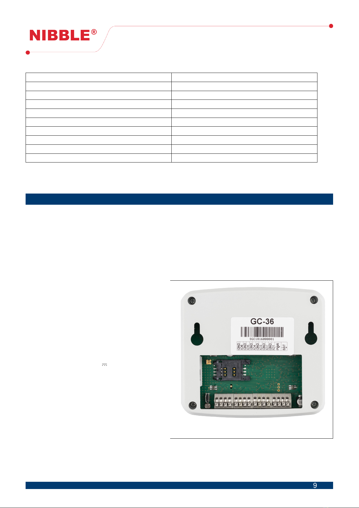
Figure 1: GC-36 rear view
Figure 1 features the rear view of the
GC-36 detailing the inputs/outputs, inter-
faces and power.
3.1 Power Supply
The module can be powered with a 12
to 32VDC power supply. Whatever the cho-
sen voltage, the power supply must provide
at least 12W (i.e.: 12V 1A) and allow for
current peaks of up to 2A. The positive ter-
minal of the transformer must be connected
to the ‘+’ terminal of the module’s PWR con-
nector and the negative to the ‘-’ terminal.
An optional rechargeable 9V Ni-MH battery
should be connected to ‘+’ and ‘-’ termi-
nals of the module’s BAT connector. For
the optimum performance of the battery, a
15VDC power supply to the module is rec-
ommended.
9
9 / 33

User Manual
Version 1.9
3.2 SIM Card
To insert the SIM card, slide the cover and insert it into the slot.
The SIM card PIN code is requested if it is not deactivated. After 3 failed attempts an error
message is displayed, the module must be restarted and the SIM card must be unlocked with the
PUK code without GC-36.
To benefit from all the features, your SIM card should allow for the sending and receiving of
SMS and phone calls.
The card can be postpaid or prepaid.
3.3 Bidirectional inputs and outputs
The bidirectional inputs and outputs can be accessed in IO1 to IO6 terminals. Each IO terminal
is accompanied by a ground terminal to facilitate the connections. Each IO terminal allows the
application of voltage levels from 0V to 40V.
Inputs
The inputs have negative logic, that is, they are activated when a ground signal is applied to
the IO terminal. To actuate on the inputs, a dry contact should be used with one of the contacts
connected to the adjacent ground terminal, as shown in figure 2. No voltage should be applied on
the inputs.
Off On
IONION
GND GND
Figure 2: Input states with dry contact
Outputs
The outputs are open collector type. When activated they close the circuit to the ground and
when deactivated they open the circuit, as is shown in figure 3. Each output allows up to 500mA
maximum current and 40V maximum voltage.
Off On
40V
Max
0.5A
Max
Figure 3: Outputs states with open collector
10
10 / 33
User Manual
Version 1.9
3.4 GSM antenna
An external GSM antenna can be connector the MMCX RF connector. The antenna is optional
as module has an internal antenna. A dual band1or quad-band2can be used.
3.5 USB interface
The USB interface allows for configuration via a Windows application, the GC configurator
(see section 7).
4 Functionalities
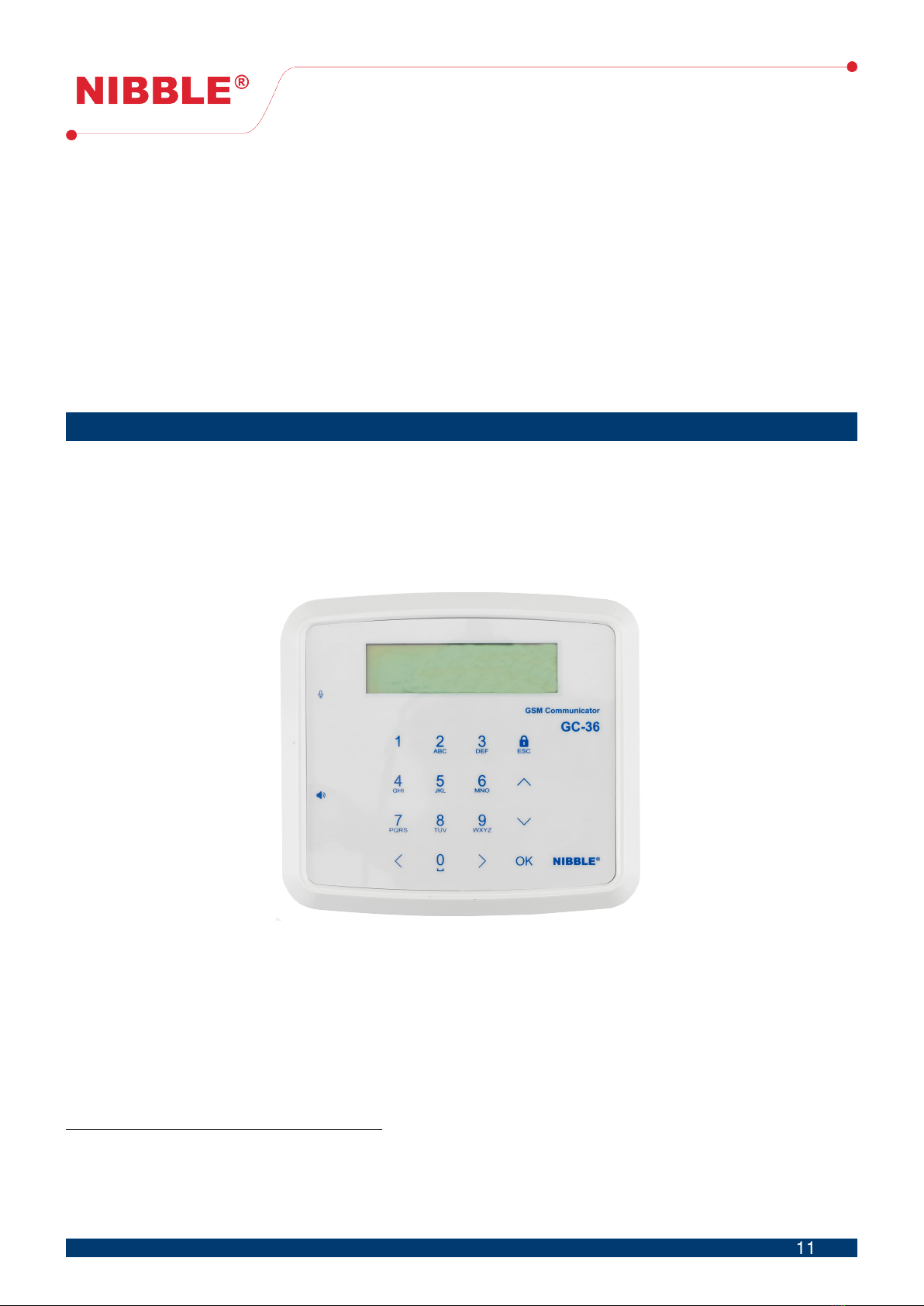
4.1 Local user interface
The GC-36 module can be configured via its local user interface, made up by a capacitive
keypad with 16 buttons, an alphanumeric LCD screen with 2x16 characters, as shown in figure 4.
Section 5 details menu navigation.
Figure 4: GC-36 local user interface
4.2 Access levels
The GC-36 module provides 3 access levels:
• Level 1 – allows arming and disarming of system;
• Level 2 – allows output actuation with SMS;
• Level 3 – allows module configuration.
1Dual-band - 900MHz and 1800MHz
2Quad-band - 850MHz, 900MHz, 1800MHz and 1900MHz
11
11 / 33

User Manual
Version 1.9
To arm the system, it is only necessary to press the button with lock symbol.
To disarm the system, it is necessary to insert a 4 digit code. The user does not need to enter
a specific menu to disarm the system. The code is configurable and is factory defined to 1234.
The user with level 2 access should enter a 4-digit code, this code being configurable and
factory defined as 1234.
The level 3 access code is also configurable and is factory defined as 123456. In the event of
level 3 access code loss, contact your distributor.
4.3 SMS configuration
The GC-36 module can be configured via SMS commands. The module must have an active
SIM card in order to allow configuration access.
Section 6 details all SMS commands.
4.4 PC configuration
The GC-36 module can be configured with a Windows application via USB connection. Section
7 details the configuration software.
4.5 Monitoring and control
The module can be monitored and controlled remotely via phone calls and SMS.
The following sections detail monitoring and control with these interfaces.
Audio and SMS notifications
It is possible to customize different audio messages of up to 5 seconds for the status changes
for any input (logic inputs, tamper and power). The module maintains a phonebook of 150 num-
bers to send these messages. Each number can be configured to receive multiple notifications
for different entries.
When a state of an input is changed (except tamper and power), the module starts sending
audio messages to the configured numbers. After receiving the phone call, the user will hear the
audio message identifying the notification. To end the notification, the user must press the number
‘0’ or ‘1’ in the phone and the module will terminate the call. If the number ‘0’ is pressed, the user
will stop receiving the notification and the module advances to the next number in the list. If the
number ‘1’ is pressed, the module will stop the notification for all numbers. If the user does not
answer the call or does not confirm the call using the numbers, the module continues to notify up
to a configurable number of attempts before giving up.
You can also configure the module to send customizable SMS for status changes to any entry.
In addition, it can be configured to send an SMS when the user does not confirm the audio
notification.
Input event alerts are disabled or enabled when the module is disarmed or armed, respectively.
12
12 / 33

User Manual
Version 1.9
Programmable outputs
The outputs can be activated and deactivated automatically, without direct interaction of the
user, by changing the state of the inputs (eg: activate a siren when an intrusion alarm is activated).
Actuation on the outputs depending on the inputs are disabled or activated when the module is
disarmed or armed, respectively.
Remote output actuation with SMS command
It is possible to actuate on the outputs remotely by sending an SMS to the module to acti-
vate/deactivate an output.
Remote output actuation with costless phone call
It is possible to actuate on the outputs with a phone call to the module. This call is automatically
rejected in order to have no cost.
Actuation on output 1 (if configured as such) by phone call, makes input 2 (if configured as
such) sensible, during 60 seconds, to state changes. If any change is detected at this input during
this time, the configured SMS for that input is sent to the phone that made the call. A possible use
for this feature is the activation/deactivation of an alarm. If there is any configuration for that input,
it is processed normally. The GC-36 executes this functionality whether the system is armed or
disarmed.
4.6 Automatic test calls
The module can be configured to send a customizable audio message, up to 5 seconds,
automatically.
This call has 2 goals, to notify the manager of the module that it is functional and to keep the
SIM card active.
Test calls can be configured as daily, weekly, or monthly.
Calls are only made to the first number in the phonebook. The module makes up to 3 attempts
to call, if the user doesn’t answer the call or doesn’t confirm using the numbers, the module sends
an SMS to the user to notify that the test call has been lost.
The time for the call, weekday (if weekly) and month day (if monthly) is configured when
the device clock is set. For example, if the date and time is configure for December 1st, 2018
(Saturday) 10:25, the calls will be made at 10:00 on Saturdays, if weekly, or at 10:00 on the 1st of
every month, if monthly.
4.7 Low SIM card balance notification
The module checks SIM card balance continuously (country restriction). When the balance
drops lower the e2.00 (assumes the currency is Euro) a low balance notification is sent to the first
number in the phonebook.
13
13 / 33

User Manual
Version 1.9
4.8 Tamper detection
After installation, it is possible to activate tamper detection. The tamper detection system
makes a phone call with a voice message to the first number in the phonebook every time the
module is removed or placed in the wall. If the user does not acknowledge or rejects the call a
backup SMS is sent indicated the event. The audio and SMS contents can be configured locally
or via PC.
Tamper detection is deactivated or activated when the module is disarmed or armed, respec-
tively. The tamper detection is located in the back of the product near the USB connector.
4.9 Power supply failure detection
The power supply failure detection system makes a phone call with a voice message to the
first number in the phonebook every time the module is removed or placed in the wall. If the user
does not acknowledge or rejects the call a backup SMS is sent indicated the event. The audio
and SMS contents can be configured locally or via PC.
4.10 Arming and disarming the system
The GC-36 can be armed and disarmed with access level 1. When the system is disarmed, all
inputs and tamper detection are deactivated, that is, all events associated with inputs and tamper
detection are not evaluated, except the feature of output actuation with costless phone call.
14
14 / 33
User Manual
Version 1.9
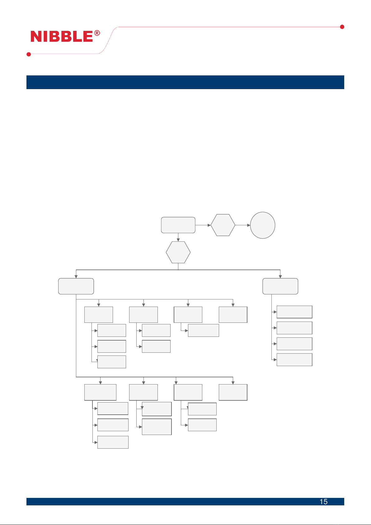
5 Local configuration
Figure 5 shows a diagram of how to navigate the menu.
From the locked screen a user can:
• Arm the system, pressing the button with the lock symbol (see figure 4);
• Disarm the system by inserting the disarm code;
• Enter configuration and diagnostic menus by pressing the button OK and inserting the level
3 access code;
• Check the current system status such as power and battery, armed or disarmed system and
ongoing call.
With level 3 permissions the user has access to the configuration and diagnostic menus. In
these menus, and subsequent submenus, the user can use the up and down arrows on the keypad
and press OK to enter, or directly press the corresponding digit (i.e. press digit 2 followed by digit
3 directly enter the GSM diagnostic submenu.
Lockedscreen Arm/Disarm
system
1.Configuration 2.Diagnostic
1.IO
configuration
2.Numbers
configuration
Name
IOdirection
Pulse
3.Tamper
Configuration
1.Inputs
diagnostic
2.Outputs
diagnostic
3.GSM
diagnostic
4.Logs
Editnumber
Newnumber
Testcall
configuration
Voicealerts
configuration
Changelevel2
code
Activate
tamper
Level1
access
4.Clock
configuration
5.Codes
configuration
6.Voice
messages
7.System
configuration
8.GSM
configuration
Keypad
sound
Change
language
Level3
access
Changedisarm
code
Changelevel3
code
Figure 5: Menu diagram
15
15 / 33

User Manual
Version 1.9
5.1 Configuration menu
In the configuration menu the user can:
1. Configure I/O;
2. Configure phonebook;
3. Configure tamper detection;
4. Configure clock;
5. Configure access codes;
6. Configure voice messages;
7. Configure the system;
8. Configure GSM.
5.1.1 Configure I/O
This submenu allows for I/O configuration as inputs or outputs, The character ‘I’ represent the
configuration as input and the character ‘O’ represents the configuration as input.
Pressing OK, leads to next submenu which allows to:
1. Configure inputs – configure SMS alerts, voice alerts and outputs actions for logic inputs,
tamper and power supply;
2. Configure I/O name;
3. Configure pulse – pulse duration, with tenths of a second precision, when configured as
output. Maximum value is 3600,0 seconds;
In the outputs actions configuration menu, the allowed characters are:
• ‘-’ – No action;
• ‘X’ – Not applicable: I/O is configured as input;
• ‘L’ – On;
• ‘D’ – Off;
• ‘T’ – Toggle;
• ‘P’ – Positive pulse;
• ‘N’ – Negative pulse.
5.1.2 Configure phonebook
This submenu allows for complete phonebook management.
To edit or delete a number, it is required to navigate to the desired number with up and down
buttons and press OK.
In the edit number submenu it is allowed to insert a phone number, configure SMS alerts, voice
alerts and outputs action with costless call.
The allowed characters for SMS and voice alerts are:
• ‘-’ – No alert;
• ‘X’ – Not applicable: I/O is configured as output;
• ‘P’ – Send on input positive transition;
• ‘N’ – Send on input negative transition;
• ‘B’ – Send on any input transition;
• ‘V’ – Send as voice alert backup (SMS only).
The allowed characters for output actions are the same as in section 5.1.1.
16
16 / 33

User Manual
Version 1.9
5.1.3 Configure tamper detection
This submenu allows for activation and deactivation of tamper.
The tamper activation must be done only after device installation on the desired place, as it
will be calibrated there. The tamper detection component is located in the back of the device next
to the USB connector.
5.1.4 Configure clock
The clock is used to log date and time events and to make periodical phone calls. To configure
the clock, the user must introduce year, month, day, hour and minute in the corresponding fields.
5.1.5 Configure access codes
This submenu allows to configure the code to disarm the system and levels 2 and 3 access
codes.
To configure the disarm code and level 2 access code it is necessary to insert the current code
and then the new code twice. These codes consist of 4 digits and are factory defined as 1234.
To configure the level 3 access code it is necessary to insert the current code and then the
new code twice. This code consists of 6 digits and is factory defined as 123456.
5.1.6 Configure voice messages
This menu allows for the configuration of voice alerts messages, cyclic or step, the number of
tries for each alert and recording/reproduction of the test message.
In the cyclic mode, when the voice alert attempts are made to a number in the phonebook,
each following attempt is made to the next number in the list. In the step mode, the attempts are
exhausted for each number before moving to the next one.
5.1.7 Configure the system
This menu allows to change the menus language and to activate/deactivate keypad sound.
5.1.8 Configure GSM
This menu allows for the configuration of test calls period, SIM card type as prepaid or postpaid
and sending of balance status in all SMS including input alerts (All option) or only in responses to
configuration and control commands (Partial option).
To improve GSM efficiency, when a postpaid card is used, configuration should be as such, so
that there are no unnecessary balance checks. In countries where balance checking is restricted
it should be configured as postpaid.
6 SMS configuration
It is possible to configure some functionalities with SMS commands from any number. Safety
is guaranteed because of the need to insert the level 2 or 3 access code in all commands. Factory
default level 2 access code is ‘1234’ and level 3 access code is ‘123456’ and both can be changed.
17
17 / 33

User Manual
Version 1.9
All SMS commands follow the base structure shown in table 3. It consists of 3 fields separated
by a comma (‘,’).
[PIN_CODE],[CMD],[ARGS]
Table 3: SMS commands base structure
All commands start with the [PIN_CODE] field which is the level 3 access code with 6 digits
(except when otherwise stated), followed by the [CMD] field which identifies the command and
[ARGS] field which includes all arguments necessary for the command. No commands or argu-
ments are case sensitive.
The SMS command sender will always receive a valid SMS response to all valid commands,
except for the PEC command where a call is received instead. The user should avoid sending
new commands before receiving the SMS reply of previously sent settings to prevent command
losses. All responses included SIM card balance if configured as such.
Commands can be divided in 2 groups:
1. Technical and configuration commands;
2. Usage and actuation commands.
All command identifiers, arguments and response SMS are explained and examplified in the
following sections.
6.1 Technical and configuration commands
6.1.1 Configure inputs and outputs
It is possible to configure inputs and outputs directions. The [CMD] field is IO. The [ARGS]
field consists of 6 characters, each corresponding to the configuration of each I/O.
If the [ARGS] field is omitted, the module responds with the current I/O configuration.
[PIN_CODE],IO,[IO1][IO2][IO3][IO4][IO5][IO6]
Table 4: I/O configuration command
Configuration codes Description
IConfigure as input.
OConfigure as output.
Table 5: I/O configuration codes
Field Description
IONThe configuration as input or output.
Table 6: Fields for I/O configuration
18
18 / 33

User Manual
Version 1.9
Example Response Description
123456,IO,IIIOOI I/Os configured I/O 1, 2, 3 and 6 configured as inputs
and 4 and 5 as outputs.
123456,IO
I/O States:
I/O1: Input
I/O2: Input
I/O3: Input
I/O4: Output
I/O5: Output
I/O6: Input
Read current I/O configuration.
Table 7: I/O configuration example
6.1.2 Configure names of I/Os
It is possible to configure the names of inputs and outputs. The [CMD] field is ION. The [ARGS]
field consists of 2 fields [IO] and [TEXT]. The [IO] field is the index of the I/O to be configured.
The [TEXT] field is the associated I/O name and shouldn’t contain accent marks in the words. If
the [TEXT] field is omitted the module responds with the current name of the I/O.
[PIN_CODE],ION,[IO],[TEXT]
Table 8: I/O names configuration command
Field Description
IO The index of the I/O to configure, 1 to 6.
TEXT The I/O name, limited to 40 characters.
Table 9: Fields to configure I/O names
Example Response Description
123456,ION,1,Water pump Changed Name I/O:1 I/O 1 name configuration.
123456,ION,4,Activate alarm Changed Name I/O:4 I/O 4 name configuration.
123456,ION,1 Name I/O:1
Water pump Read name of I/O 1.
123456,ION,4 Name I/O:4
Activate alarm Read name of I/O 4.
Table 10: Example of configuration of I/O names
6.1.3 Configure alert SMS
It is possible to configure the SMS associated with input alarms. The [CMD] field is IONUD.
The [ARGS] field consists of [IO], [TEXT_UP] and [TEXT_DN]. [IO] is the index of the input
to be configured. [TEXT_UP] is the text associated with SMS alert on input activation and
[TEXT_DOWN] is the text associated with SMS alert on input deactivation. [TEXT_UP] and
[TEXT_DOWN] shouldn’t contain accent marks in the words.
19
19 / 33

User Manual
Version 1.9
If [TEXT_UP] and [TEXT_DOWN] are omitted, the module responds with the input’s current
configuration.
[PIN_CODE],IONUD,[IO],[TEXT_UP],[TEXT_DN]
Table 11: SMS alerts configuration command
Field Description
IO The index, 1 to 6, of the I/O to be configured.
TEXT_UP The text associated with input activation.
TEXT_DN The text associated with input deactivation.
Table 12: Fields to configure SMS alerts associated with input events
Example Response Description
123456,IONUD,1,Alarm on,Alarm off UP/DN name changed I/O:1 Configuration of texts
of I/O 1.
123456,IONUD,1
Name I/O:1
Text UP: Alarm on
Text DN: Alarm off
Read texts of I/O 1.
Table 13: Example of configuration of SMS associated with input events
6.1.4 Configure outputs actions on input events
The field [CMD] is OUP or ODN for activation or deactivation respectively. [ARGS] consists of
the field [IO] and the fields [A1], [A2], [A3], [A4], [A5] and [A6]. The [IO] field is the index of the input
to be configured. The [AN] fields are the actions (see table 15) to trigger on output N.
If the [AN] fields are omitted, the modules responds with the current configuration of the asso-
ciated input.
[PIN_CODE],OUP,[IO],[A1][A2][A3][A4][A5][A6]
[PIN_CODE],ODN,[IO],[A1][A2][A3][A4][A5][A6]
Table 14: Commands to configure outputs actions on input events
Configuration code Description
LOn.
DOff.
TToggle.
PPositive pulse.
NNegative pulse.
0No action.
XKeeps the previous configuration.
Table 15: Codes to configure output actions
20
20 / 33
Other manuals for GC-36
1
Table of contents
Other NIBBLE Cell Phone manuals


