Nico Technology myriad-LX User manual

LIT-218 NICO Corporation
Rev. C (English)
Page 1 of 22
(Patent 9,772,094)
Xenon Illuminator with Digital
Dimming Control
Operator Manual
DIST NICO Corporation
250 E 96TH Street
Suite 125
Indianapolis, IN 46240 USA
Sunoptic Technologies ®
6018 Bowdendale Avenue
Jacksonville, FL 32216 USA
EC|REP AJW Technology Consulting GmbH
Königsallee 106
40215 Düsseldorf, Germany
+49 (0) 211 3013 2232

LIT-218 NICO Corporation
Rev. C (English)
Page 2 of 22
TABLE OF CONTENTS
1. INTRODUCTION
1.1 INDICATIONS FOR USE
2. WARNINGS / CAUTIONS
3. SPECIFICATIONS
4. OPERATING ELEMENTS, SYMBOLS AND FUNCTIONS
4.1 FRONT PANEL
4.2 REAR PANEL
5. INSTALLATION
5.1 SETTING UP ILLUMINATOR
5.2 CONNECTING LIGHT CABLE
6. OPERATION
6.1 POWERING UP ILLUMINATOR
6.2 TOUCH SCREEN FUNCTIONS
6.2.1 FAULT CONDITION NOTICES
6.2.2 NORMAL OPERATING DISPLAY
6.2.2.1 LAMP HOURS DISPLAY
6.2.2.2 LIGHT BRIGHTNESS CONTROL
6.2.2.3 STANDBY
6.2.2.4 MENU
6.2.2.4.1 RESET FILTER
6.2.2.4.2 ERROR LOG
6.2.2.4.3 TOTAL UNIT HOURS
6.2.2.4.4 FIRMWARE VERSIONS
6.2.2.4.5 LANGUAGE
7. CLEANING and DISINFECTION
8. MAINTENANCE, SERVICING & REPAIR, WARRANTY
8.1 FILTER REPLACEMENT
8.2 LAMP REPLACEMENT
8.3 REPLACEMENT COMPONENTS
8.4 LIMITED WARRANTY
9. END OF PRODUCT LIFE
10. TROUBLESHOOTING
11. CHART OF MEDICAL AND ELECTRICAL DEVICE SYMBOLS USED
11.1 CHART OF MEDICAL DEVICE SYMBOLS USED
11.2 CHART OF ELECTRICAL SYMBOLS USED

LIT-218 NICO Corporation
Rev. C (English)
Page 3 of 22
1. INTRODUCTION
Congratulations on the purchase of your new MyriadLX™ Xenon Illuminator!
The Myriad-LX light source is a high-intensity 300W Xenon Illuminator with touch screen and
digital dimming controls. The light source is fitted with a proprietary connector to ensure usage is
reserved for the NICO Myriad NOVUS™ system. For setup and instructions related to other
components of the Myriad NOVUS, refer to their respective labeling or manuals.
The Myriad-LX is a high efficiency light source utilizing state-of-the-art illumination technology. It
offers a variety of features such as:
5600 K color temperature provides daylight brightness for perfect color definition
Quiet operation
Compact and light weight
Autoshutter turret
Air filter to mitigate dust/lint buildup inside the cabinet
Digital dimming
Easy lamp replacement
This Operator’s Manual provides instruction for use of the illuminator and how to keep it clean. It
includes maintenance and service guidelines as well as recommendations for best performance
results.
1.1 INDICATIONS FOR USE: The intended use of this device is to provide light for fiberoptic
cables and instruments – providing light for instrumentation via fiberoptic cables for use in
surgical fields.

LIT-218 NICO
Corporation
Rev. C
(English)
Page 4 of 22
2. WARNINGS/ CAUTIONS
WARNING The illuminator produces a highly concentrated (luminous energy per unit area) light beam
and this high energy density is retained through any connected lightguides and instruments. The output of a
connected instrument left in close proximity or contact with tissue or flammable materials presents a risk of
injury or fire. Qualified personnel must determine a safe working distance and intensity setting for each
application. The illuminator should never be left on unattended.
Caution Rx only. Federal law restricts this device to sale by or on the order of a licensed healthcare
practitioner.
Caution To prevent fire or electric shock, do not open or expose the illuminator unit to rain or
moisture. Refer all servicing to qualified personnel only.
Caution Not suitable for use in presence of flammable anesthetic mixture with air or with oxygen or
nitrous oxide.
Caution This equipment is suitable for use in hospital and clinical settings. Avoid placement near
other high RF equipment; user should determine proper placement and confirm normal operation of
equipment when stacked or used near or with other RF equipment.
Caution This product should be used only with type BF endoscopic instruments which have been
certified according to IEC 60601-1 for medical equipment and IEC 60601-2-18 for endoscopic equipment.
This symbol indicates type BF equipment.
Caution User must not alter this device in any fashion. Doing so voids all warranties and statements
of suitability for any purpose.
Caution All devices connecting to the Illuminator must be classified as medical equipment. Additional
information processing equipment connected to the Illuminator, a Medical System and the operator must
determine that all equipment complies with the appropriate end-product standards (such as IEC 60950 or
IEC 60065 and the Standard for Medical System, IEC 60601-1-1).
Caution Always set the intensity control to the minimum level and insert the fiberoptic cable into the
unit before turning on the power. When light is not required at the surgical site, the intensity control should
be set to the fully dimmed position. If it becomes necessary to remove the fiberoptic cable without turning
the unit off, turn the intensity control to the fully dimmed position.
Caution The fiberoptic cable used with this illuminator must be electrically NON-CONDUCTIVE.
It should not have conductive shielding or any other conductive connection between the patient and
equipment. Such connection will impair safety of the equipment. Ensure the optical surface is clean before
connecting the cable to the illuminator.
Caution When using high intensity illuminators at full output, the recommended from working
distance to the patient is not less than 12 inches (30.5 cm). If using less than 12 inches from the patient,
the light intensity must be reduced.
Caution This equipment is intended to illuminate a surgical site; user is responsible for determining if
interruption of light output, including due to effects from electromagnetic disturbances, will create an
unacceptable risk. If such a determination is made, alternate arrangements (such as a standby illuminator)
should be made by the user to reduce the risk.
LIT-218 NICO Corporation
Rev. C (English)
Page 5 of 22
Caution Use of this illuminator with accessories or attachments requires that the end-user follow all
accessory or attachment instructions which could affect illuminator setup, usage and/or settings.
Caution This device contains stored electrical energy, follow operating instructions when changing
lamp.
Caution Do not remove lamp immediately after operation. Allow lamp to cool 10 minutes.
Caution To prevent overheating, replace only with the same type and rating of lamp. Read
instructions before replacing lamp.
Caution Do not operate illuminator without lamp in place.
Caution For grounding reliability, use only hospital grade marked power cord and receptacle.
Caution Disconnect power supply cord before servicing to avoid electrical shock.
Caution To reduce risk of electrical shock, do not remove cover. Refer servicing to qualified
personnel.
Caution Illuminator can cause permanent eye damage if viewed directly with unprotected eye.
Caution Do not reach hand inside unit due to risk of shock hazard.
Caution Use only approved manufacturer accessories and power cables. For more information,
contact your distributor.
LIT-218 NICO Corporation
Rev. C (English)
Page 6 of 22
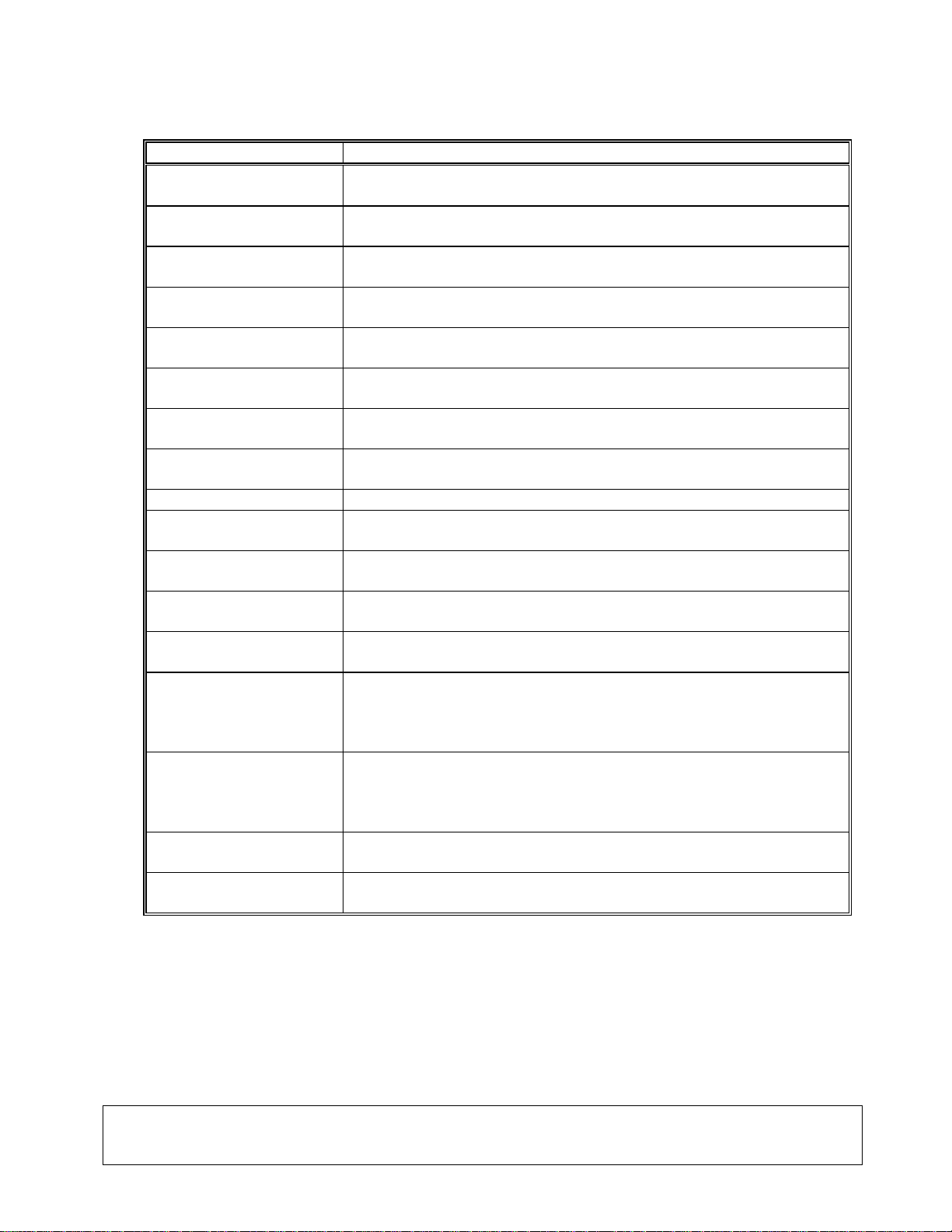
3. SPECIFICATIONS
Item Specification
Lamp type Ceramic type 300 watt Xenon
Power 300 Watt
Color temperature 5600 K
Lamp life 1000 hours (typical)
Lamp replacement Cartridge replacement from the side of the unit
Light guide adapter
NICO proprietary
Brightness control Mechanical progressive shutter control from the front panel
Input voltage
100-120 V AC, 50/60 Hz
220-240 V AC, 50 Hz
Power consumption 750 watt max
Regulatory Approvals UL60601, EN 60601-1, EN 60601-1-2, CAN/CSA, C22.2,
No 601.1-M90
Equipment Class BF-type, Conforms to CISPR 11 Class A
Mode of Operation Continuous operation
Water Resistant Not Protected Equipment, IPX0
Operating Environment
Temperature
Relative Humidity
Air Pressure
+20° to +40° C (68° to 104° F)
30 to 85%
700 to 1060 hPa
Storage Environment
Temperature
Relative Humidity
Air Pressure
-20° to +60° C (-4° to 140° F)
0 to 95%
700 to 1060 hPa
Dimensions, mm (inch) 338 (13.3) Width x 155 (6.1) Height x 457 (18) Depth front-to-
back
Weight, kg (lb) 10kg (22lb)

LIT-218 NICO
Corporation
Rev. C
(English)
Page 7 of 22
4. OPERATING ELEMENTS, SYMBOLS AND FUNCTIONS
4.1 FRONT PANEL
4 (TOP LINE)
1 2 3
Illuminator Front Panel
No. Name Function
1. Lamp switch Turns the illuminator on and off; illuminates blue when turned on
2. Touch screen Controls light intensity, displays notices and accesses data
3.
Turret
Autoshutter turret accepts end tip of fiber optic cable; light is
shuttered off when no cable is inserted
4. Lamp Hours Display Displays total hours of lamp use
LIT-218 NICO Corporation
Rev. C (English)
Page 8 of 22
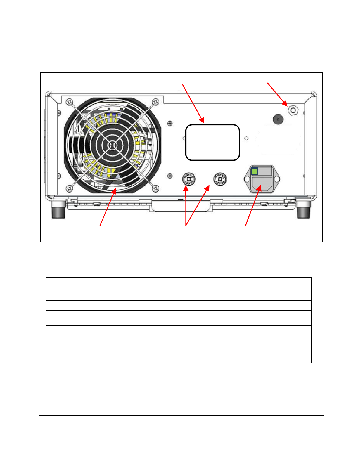
4.2 REAR PANEL
4 5
1 2 3
Illuminator Rear Panel
No. Name Function
1. Fan Fan 12V DC, airflow for cooling of unit
2. Circuit breaker Over current protection
3. AC mains power switch
and input module Accepts AC Power cord and switches on AC power
(Green light indicates “on”)
4.
Product label Product Label containing: Model Number, Serial Number,
Electrical Ratings, Manufacturer Name, Regulatory
Marks and FDA “Rx Only” Symbol
5. Grounding Connector For electric potential equalization
LIT-218 NICO Corporation
Rev. C (English)
Page 9 of 22
5. INSTALLATION
5.1 SETTING UP THE ILLUMINATOR
Place the illuminator within the low on shelf of the supplied NICO Myriad NOVUS cart.
NOTE If used without the required NOVUS cart, avoid locations where the
illuminator may be splashed with liquid.
DO NOT use in any environment with explosive or flammable gases.
This illuminator pulls cooling air into its cabinet through a filtered grille in the
bottom panel underneath the front portion and exhausts warm air from the fan in
the rear.
DO NOT block the space in front or below the front of the illuminator or impede
exhaust air flow behind or above the cabinet.
If used without the required NOVUS cart a clear space minimum of 5”/12.7cm
behind and above the cabinet is required.
The illuminator should not be placed where its exhaust will influence other devices,
nor where exhaust from other devices will influence the illuminator.
Ensure the rear power switch is in OFF position.
Ensure that the lamp is properly positioned for use. Open the lamp compartment door.
Move the lamp positioning lever (found to the right of the lamp) clockwise, from horizontal
to vertical. As the positioning cones disengage the lamp should drop about 3mm. Move
the lamp positioning lever counterclockwise to reengage the positioning cones and
observe that the lamp rises about 3mm as it returns to operating position.
Close the lamp compartment door.
Connect AC power cord to the power inlet located on the rear panel of the illuminator.
Ensure the power cord is completely seated into the power inlet and engage the cord
retainer if so equipped.
CAUTION
Use only power cords provided with the illuminator.
Plug the AC power cord into a wall outlet using the three (3) prong plug
supplied with the unit.
CAUTION
To prevent electric shock, connect power cords of peripheral equipment
through medical isolation transformers.
NOTE When using medical isolation transformer, be sure to check the transformer
power ratings. Ensure that the power cord is connected to the main power with
three prong plug (USA use UL2601-1 rated isolation transformers and/or power
strips only).
CAUTION Nearby radio or TV units may subject this equipment to radio interference.
To avoid adverse electromagnetic effects, DO NOT operate this equipment
near RF energy equipment.

LIT-218 NICO
Corporation
Rev. C
(English)
Page 10 of 22
5.2 CONNECTING THE Myriad-LX FIBER
Connect the Myriad-LX Illumination fiber to the Myriad Handpiece per the relevant IFU.
Insert the Illumination Fiber’s proximal connector into the port of the turret on the front
panel.
You may notice a very slight normal resistance to insertion as the tip opens the auto
shutter. Push the tip all the way in.
6. OPERATION
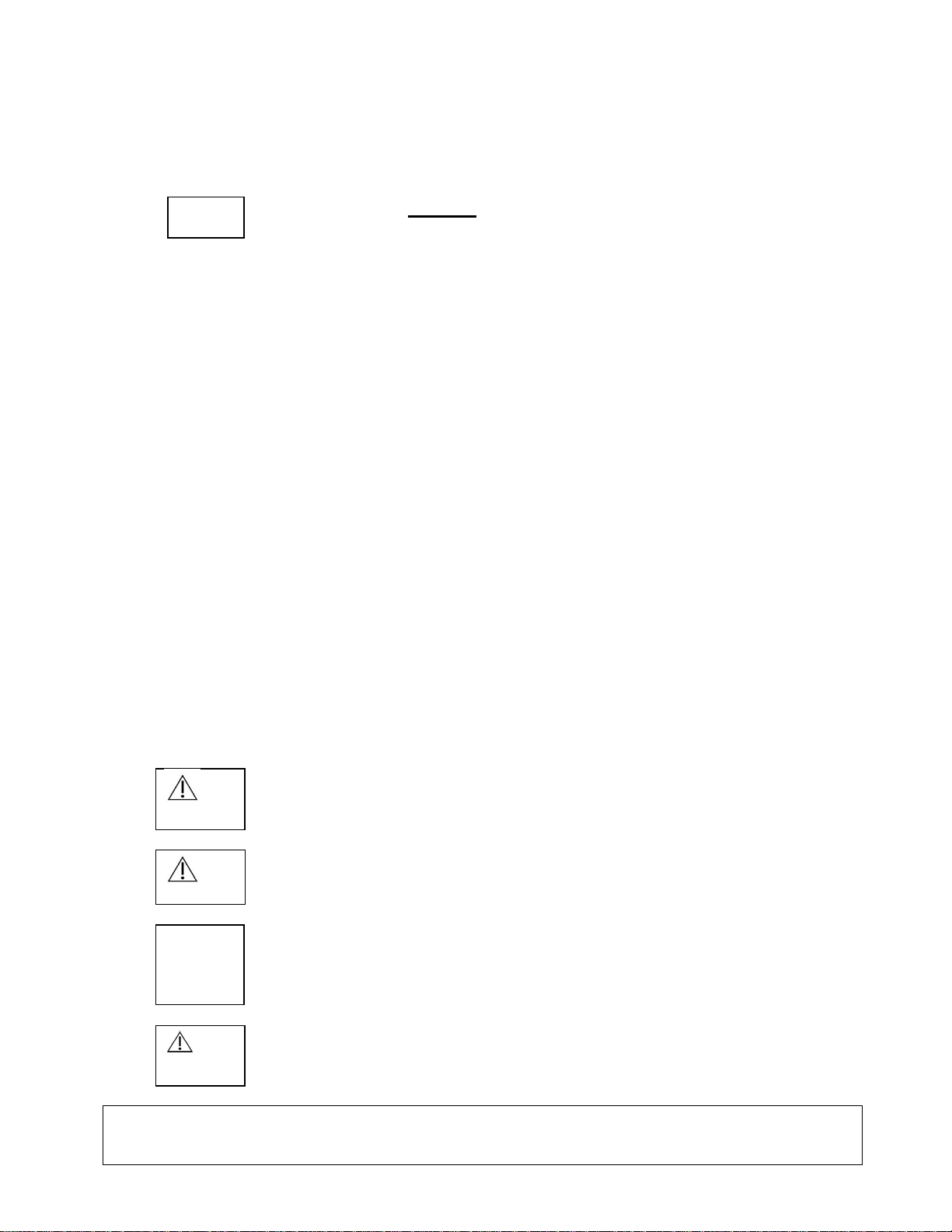
6.1 POWERING UP THE ILLUMINATOR
To operate the illuminator: First attach the fiber to the
ILLUMINATOR
.
Turn on the rear power switch. Turn on the front lamp switch.
The lamp switch will light up and the fan will start. The touch screen will display
for three seconds, followed by the normal operating display:
6.2 TOUCH SCREEN FUNCTIONS
6.2.1 FAULT CONDITION NOTICES
There are twelve fault conditions detectable by sensors that will render the illuminator
inoperable until they are corrected. A fault condition notice will appear on the screen
identifying the fault and how to correct it.

LIT-218 NICO Corporation
Rev. C (English)
Page 11 of 22
6.2.1.1 ENGAGE LAMP
(Refer to 8.1 LAMP REPLACEMENT) Disconnect power. Open the door. The lamp
positioning lever should be completely down(horizontal) to properly engage the lamp
and completely up (vertical) to release it. Raise the lever completely if not already
raised and firmly push the lamp to assure full engagement to the power connectors.
Lower the lamp engagement lever counter-clockwise, from vertical to horizontal, and
observe that the lamp rises slightly as it is engaged into proper operating position.
6.2.1.2 CLOSE DOOR
Close the door completely. (Fan will continue to run with door open.)
6.2.1.3 INCOMPATIBLE LAMP MODULE INSTALLED
Install correct STX0350 lamp.
The digital control system communicates with Sunoptic Technologies®lamps
designed for it. Only Sunoptic Technologies®lamps can be engaged by the
positioning mechanism.

LIT-218 NICO
Corporation
Rev. C
(English)
Page 12 of 22
6.2.1.4 INCORRECT WATTAGE LAMP INSTALLED
Install correct STX0350 lamp.
Installed lamp does not match the intended power (watts). Tx350 units require a 300-watt lamp.
6.2.1.5 LAMP HAS EXCEEDED USEABLE LIFE
Lamp has been used more than 1000 hours. Install new STX0350 lamp or one used
less than 1000 hours. The main screen always displays lamp hours, and notices are
displayed when a lamp is approaching the end of its useful lamp life. This screen is
displayed when the lamp has exceeded its usable lifetime.
6.2.1.6 FAN FAULT
In the event of a fan problem the unit will turn off the lamp and display this screen.
Turn off and restart the illuminator. If the fault persists the unit needs servicing.

LIT-218 NICO Corporation
Rev. C (English)
Page 13 of 22
6.2.1.7 DIMMER CALIBRATION ERROR
On start-up the system calibrates the dimmer plate position. If the process fails, this
screen will display and the lamp will not ignite. Turn off and restart the illuminator. If the
fault persists the unit needs servicing.
6.2.1.8 LAMP FAULT
Lamp will not strike or stay lit. Replace the lamp. If the fault persists the unit needs
servicing.
6.2.1.9 LAMP COMMUNICATION FAULT
This screen is displayed when the control system does not get a response from the lamp
during startup. Turn off and restart the illuminator. If the fault persists the unit needs
servicing.
LIT-218 NICO Corporation
Rev. C (English)
Page 14 of 22
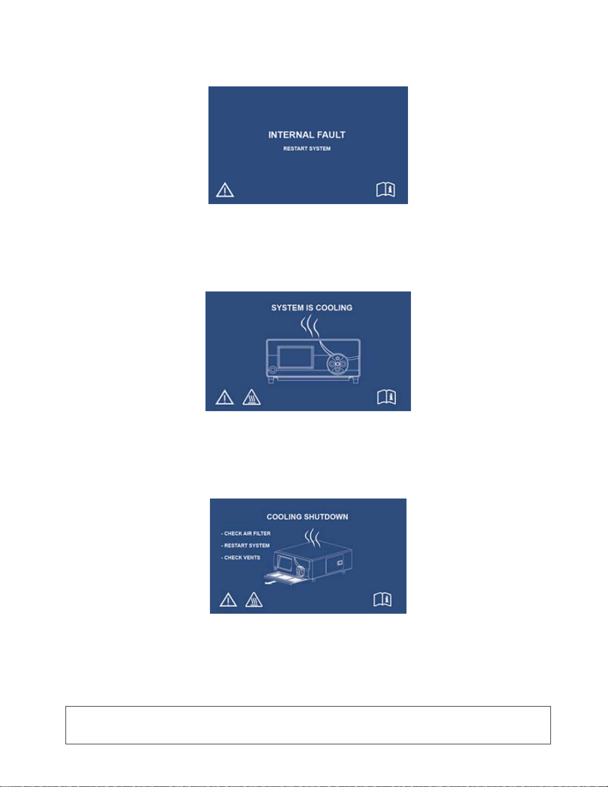
6.2.1.10 INTERNAL FAULT
This screen is displayed whenever the control systems detect a fault between its two
processors. Turn off and restart the illuminator. If the fault persists the unit needs
servicing.
6.2.1.11 SYSTEM IS COOLING
If the lamp temperature exceeds preset limits the lamp will go off and this screen will display.
The fan will run to reduce the temperature. If acceptable reductions achieved within ten
seconds, the lamp will turn back on to resume normal operation.
6.2.1.12 COOLING SHUTDOWN
If cooling pauses are unable to acceptably restore acceptable operating temperature the
lamp will go off and this screen will display. Follow the instructions (check the air filter,
restart, check for obstructions that would impede intake air flow under the front of the
unit or exhaust air flow from the rear of the unit). If the fault persists the unit needs
servicing.
LIT-218 NICO Corporation
Rev. C (English)
Page 15 of 22
6.2.2 NORMAL OPERATING DISPLAY
6.2.2.1 LAMP HOURS
Shows total lamp on hours.
LampHours:950
Intensity Adjust
100
_
MENU STANDBY
+
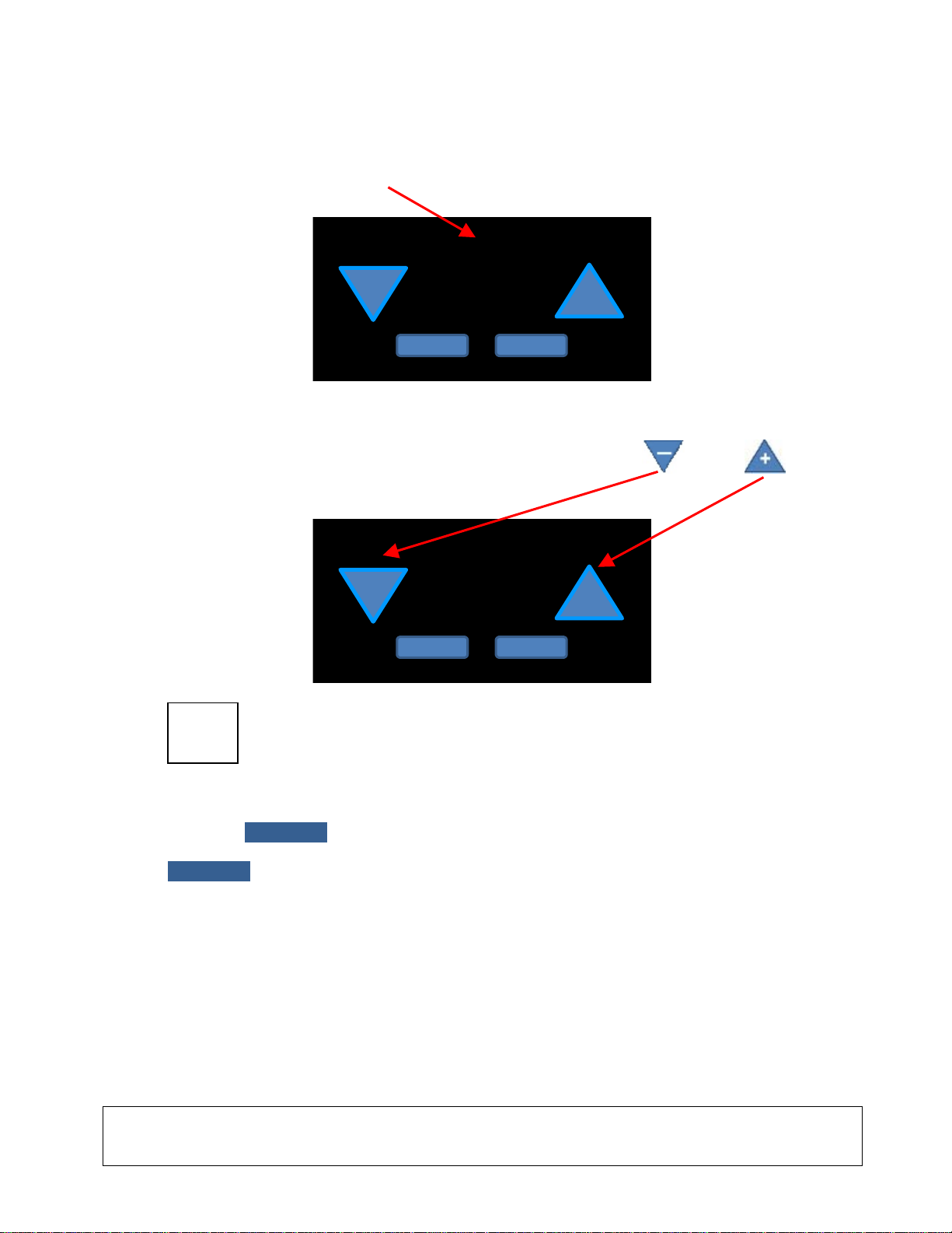
6.2.2.2 LIGHT BRIGHTNESS CONTROL
The user may adjust the light brightness by touching the minus or plus controls
on the normal operating display touch screen.
LampHours:950
Intensity Adjust
100
_
MENU STANDBY
+
NOTE The brightness control operates a progressive electro-mechanical shutter. The
lamp is running at full power if the power switch is on no matter where the
brightness control is set.
6.2.2.3 STANDBY
Touching STANDBY dims, the light by moving the shutter to fully occlude it and “softly”
(not strobe) flashes the word “STANDBY” on/off in one second Intervals. Touching
STANDBY again while in STANDBY mode will restore the light to the preset brightness
value showing on the screen.

LIT-218 NICO Corporation
Rev. C (English)
Page 16 of 22
6.2.2.4 REPLACE LAMP SOON
LampHours:950
ReplaceLampSoon
Intensity Adjust
100
_
MENU STANDBY
+
The Replace Lamp Soon message is an information warning and does not require any
action from the user. This message displays whenever the currently installed lamp has
reached 950 hours of usage. This message begins to flash whenever the lamp reaches
975 hours of usage. This warning is shown because the lamp will no longer turn on when
the lamps usage reaches 1000 hours.
6.2.2.5 CHANGE FILTER AND RESET
LampHours:950
ChangeFilterandReset
Intensity Adjust
100
_
MENU STANDBY
+
The Change Filter and Reset message is displayed flashing whenever the unit runtime
hours an increment of 250 hours (250, 500, 750, 1000, 1250, etc.). Every 250 hours the
unit filter is supposed to be replaced in order to keep the unit, and the lamp, cool enough
to avoid damage. After replacing the filter, the user must go into the Filter Reset menu and
press the Reset Filter button in order to clear this warning.
6.2.2.6 MENU
The MENU button gives the operator access to five functions of information and control.
Repeatedly touching the MENU button will cycle through the five MENU functions, as
follows:

LIT-218 NICO Corporation
Rev. C (English)
Page 17 of 22
6.2.2.6.1 RESET FILTER
ResetFilter
MENU
RESETFILTER
LampHours:250
This screen will advise if the air filter is due for replacement. Air filter replacement every
250 hours of unit operation is advised. When air filter replacement is due there will be a
flashing signal to the left of CHANGE FILTER AND RESET.
After installing a new filter, touch RESET FILTER to turn off the flashing signal for the next
250 hours of unit operation.
6.2.2.6.2 ERROR LOG
E1
_
ErrorLog
MENU
+
LampHours:20
The error log function displays error codes useful for repair service. The minus or
plus controls will cycle through the error codes logged.
6.2.2.6.3 TOTAL UNIT HOURS
248
TotalUnitHours
MENU
12/APR/2016 02:39:26
20LampHours:
Displays total hours of unit powered up operation (rear panel mains power switch on.)

LIT-218 NICO Corporation
Rev. C (English)
Page 18 of 22
6.2.2.6.4 FIRMWARE VERSIONS
A.0
+
_
FWDate
MENU
K70
LampHours:20
Displays the firmware dates of the two processors (K70 and PIC.) The minus or
plus controls will cycle between them.
6.2.2.6.5 LANGUAGE
+
English
MENU
Language
20
_
LampHours:
The minus or plus controls will cycle through the choices of variation languages.
Press menu to enter desired language.
To get back to default English language press menu to cycle thru functions
until back to English language button shows up; as per example below:

LIT-218 NICO Corporation
Rev. C (English)
Page 19 of 22
7. CLEANING AND DISINFECTION
NOTE Always disconnect the power cord before cleaning the system and while
unit is drying if wet-wiped.
Disinfection agents should be commercially available cleansers commonly used for
disinfection of electronic equipment in hospitals, such as ethyl or isopropyl alcohols, or
disinfecting sprays containing quaternary ammonium compounds or hydrogen peroxide.
Do not use strongly caustic or acidic cleansers such as “Clorox” hypochlorite bleach,
ammonia, muriatic acid or similar products. Do not use acetone, methyl ethyl ketone or
halogenated / chlorinated hydrocarbon solvents or cleaners containing any of these restricted
compounds.
Apply cleaning agents by light spray or dampened towels. Do not pour liquids over the
cabinet.
Do not allow liquids to enter the cabinet seams or ventilation openings.
8. MAINTENANCE, SERVICING AND REPAIR, WARRANTY
Performance of routine maintenance is essential to proper operation of the illuminator.
Follow the steps below for replacing filters and lamps.
Regular diagnostics can contribute to identifying potential problems before they become
serious; thus, enhancing the instrument’s reliability and extending its useful operating life.
Diagnostic services can be obtained from your local representative.
Defective items or equipment are to be serviced and repaired exclusively by persons
authorized by the manufacturer. All repair work shall employ original manufacturer’s parts
only.
8.1 Filter Replacement
Every 250 operating hours the air filter must be replaced. The time for replacement is
notified by the system software (see paragraph 6.2.2.4.2). To replace the filter:
Slide open the filter drawer located under the lightsource (it is labeled FILTER – PULL)
Remove and dispose of old filter
Obtain a new filter from the accessories kit and place into filter drawer
Close filter drawer
Reset filter message per paragraph 6.2.2.4.3
LIT-218 NICO Corporation
Rev. C (English)
Page 20 of 22
8.2 Lamp Replacement
WARNING!
CERAMIC lamps are at high internal pressure when cold and at operating temperature;
therefore, CERAMIC lamps may unexpectedly rupture resulting in discharge of hot fragments
of quartz and/or glass and metal.
Only handle lamps with protective covers in place. Do not handle lamps without their
protective covers unless government approved safety glasses, facemasks (with neck
protector, chest protector and gauntlets) are worn.
This illuminator is designed to use Sunoptic Technologies®p/n STX0350 lamp module
ONLY. Use of any other lamp may void the warranty.
To replace the lamp:
Open the lamp compartment door.
Move the lamp positioning lever (found to the right of the lamp) clockwise, from
horizontal to vertical, and pull the lamp cartridge out. Grasp only the horizontal top
and bottom grip flanges of the plastic housing of the lamp, pull straight out to remove
the lamp.
Insert a new lamp, pushing firmly to assure full engagement to the power connectors.
Lower the lamp engagement lever counter-clockwise, from vertical to horizontal, and
observe that the lamp rises about 3mm as it moves to its proper operating position.
Close the lamp compartment door.
Re-connect the power cord and turn the light source on according to 6.1. to verify that
the new lamp works and is properly installed.
NOTE
If the tamper seal on the illuminator is broken, the WARRANTY WILL BE
VOIDED. There are no other user serviceable parts in the unit.
CAUTION
Do not touch the lamp and patient simultaneously when changing the
lamp.
CAUTION
Always disconnect power cord and turn main switch off before lamp
replacement.
CAUTION
Take utmost care not to hit gas-seal edge of lamp; it may cause gas
lamp failure.
CAUTION
Lamp power connection pins at the back of the lamp compartment may
retain stored energy. Do not contact the lamp power connectors in the back
of the lamp compartment.
Table of contents


