Nicotra Gebhardt FAN Commander 200 User manual
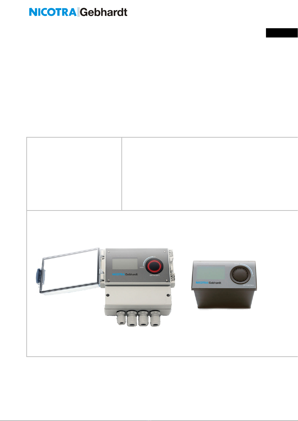
Operating Manual “FAN Commander 200” ECE 03-0200-5E-MG Seite 1 on 24
Operating manual EN
FAN Commander 200
BA-ECE 03 – Release 2020-04-06
ECE 03-0200-5E- M
D 155444 D 155445

Operating Manual “FAN Commander 200” ECE 03-0200-5E-MG Seite 2 on 24
Warn
ing
Present operating manual is a part of the product.
Before installing and using you ha e to read all safety
instructions, warnings and cautions carefully. Make
sure that the warning labels are in readable
conditions, replace missing or damaged ones.
Contact data for further information
Nicotra Gebhardt GmbH
Gebhardtstraße 19-25 Phone: +49 (0)7942 / 101 - 0
74638 Waldenburg
Germany E-Mail: Info.ng.de@regalbeloit.com
Table of Content
1
General Information....................................................................................................... 3
2
O er iew ....................................................................................................................... 6
3
Features ........................................................................................................................ 6
3.1
Basic features of the de ise .................................................................................... 6
3.2
Inputs and Outputs ................................................................................................. 6
3.3
Fan Network – RS485 link ...................................................................................... 7
4
Installation ..................................................................................................................... 8
4.1
Ambient Operating Conditions ................................................................................ 8
4.2
Mechanical Installation ........................................................................................... 9
4.2.1
Wall-Mounted Style .......................................................................................... 9
4.2.2
Counter-Sunk Style .......................................................................................... 9
4.3
Electrical Installation ............................................................................................. 10
4.3.1
Connection O er iew ..................................................................................... 10
4.3.2
Description Connection .................................................................................. 11
4.3.3
Connection Details ......................................................................................... 11
4.3.4
Connection Example ...................................................................................... 14
4.3.5
Wiring of Nicotra Gebhardt FFU Controller .................................................... 15
5
Working with the FC 200 ............................................................................................. 16
5.1
Software ............................................................................................................... 16
5.2
Commissioning ..................................................................................................... 17
5.2.1
Quick Commissioning – fan dri en by speed setting ...................................... 17
5.2.2
Quick Commissioning – fan dri en by closed loop control ............................. 17
6
Technical Data ............................................................................................................ 18
6.1
Connection ........................................................................................................... 18
6.2
Housing ................................................................................................................ 18
6.3
Ambient Operating Conditions .............................................................................. 18
6.4
IN/- and OUTPUTs ............................................................................................... 19
6.5
Fan Network ......................................................................................................... 19
7
Additional Hints ........................................................................................................... 20
7.1
Manufacturing ....................................................................................................... 20
7.2
Packing and Shipping ........................................................................................... 20
7.3
Ser ice .................................................................................................................. 20
8
Notes ........................................................................................................................... 21

Operating Manual “FAN Commander 200” ECE 03-0200-5E-MG Seite 3 on 24
1 General nformation
Definition and Meanings
For all different safety instructions special symbols are used in this manual.
Follow all hints and warnings to a oid any injury or material damage. The user of the
de ice is fully responsible.
Warnings
„Warning“ indicates that death, se ere personal injury or extensi e
property damage can result if proper precautions are not taken.
Danger
„Danger“ indicates an immediate risk of electric shock which will
result in death, injury or serious damage if the applicable safe
ty
regulations are not followed
Caution
The symbol refers to a possible hazardous situation that could
cause material or en ironmental damage.
Recommendation and useful information and ad ices for an efficient
operation free of malfunctions and faults.
Qualified personal only
Only qualified person(s) must operate with the present de ice. This qualified personal
must be familiar to these types of products and associated with danger and risks,
authorized to install, mount, commission and use these types of product.
Designated use
Use this de ice only in the manner intended by the manufacturer, according to the manual
and only in combination with the described products only.
Safety nstructions
All Warnings, Cautions and Hints shown in this document are pro ided for your safety and
as a means of pre enting damage to the product. This section lists Warnings, Cautions
and Hints, which apply generally when handling the FC 200, classified as General,
Transport & Storage, Commissioning, Operation, Ser ice and Repair. Specific Warnings,
Cautions and Hints that apply to certain specific chapters are listed at the beginning of the
rele ant chapters. Please read the information carefully, since it is pro ided for your own
personal safety and it will also help prolong the ser ice life of your product.
Operating Manual “FAN Commander 200” ECE 03-0200-5E-MG Seite 4 on 24
Warn
ing
This equipment controls potentially dangerous rotating mechanical
parts. Noncompliance with Warnings
or a miss to follow the
instructions contained in this manual can result in loss of life, se ere
personal injury or serious damage to property.
Only suitable qualified personal
should work on this equipment,
and only
after becoming familiar with all safety notices, installation,
operation and maintenance procedures contained in this manual.
The successful and safe operation of this equipment is
dependent
upon its proper handling, installation, operation and maintenance.
Children and the general public must be pre ented from accessing
or approaching the equipment!
nformation
Keep these operating
instructions within easy reach of the
equipment and
make them a ailable to all users. Whene er
measuring or testing has to be
performed on li e equipment suitable
electronic tools should be used.
Before installing and commissioning, please read these saf
ety
instructions and
warnings carefully and all the warning labels
attached to the equipment.
Transport & Storage
Warning
Correct transportation and
storage, erection and mounting, as well
as careful operation and maintenance are essential for proper and
safe operation of the equipment.
Protect the de ice against physical shocks and ibration during
transport and
storage. Also be sure to protect it against water
(rainfall) and excessi e temperatures.

Operating Manual “FAN Commander 200” ECE 03-0200-5E-MG Seite 5 on 24
Commissioning and Operation
Warn
i
ng
Use for intended purpose only.
The manual of the controlled fan
regardless whether type of fan it
is, is unconstrained by
advices in this manual, especially in questions of safety.
Some
parameter and settings lead to automatic restart of controlled fan
after switch-on.
Service & Repair
Warn
i
ng
Repairs and Ser ice on the de ice may only be carried out or
ad ised by
Approbations
All de ices of the FC 200 series are manufactured according
D RECT VE 2011/65/EU on the restriction of the use of certain hazardous
substances in electrical and electronic equipment
under consideration of the following harmonized standard:
EN 50581:2012.
Operating Manual “FAN Commander 200” ECE 03-0200-5E-MG Seite 6 on 24
2 Overview
All de ices of brand FC 200 (ECE 03-0200-5E-MG) are a stand-alone monitoring and
control unit for up to 200 fans with RS485-based interface of different brands.
A clear and simple menu guide has been realised bilingual (English/German) and offers a
ery easy access to 2 separate, free configurable and indi idual operating closed loop
cycles (Volume, Pressure, Temperature …).
The de ices are chose able as IP65-wallmounted solution or IP20-counter sunk design
a ailable with identic functions as well as customized OEM-solution in front design and
software.
3 Features
3.1 Basic features of the devise
main supply 24V DC @ 100 mA
Usage/addressing Standalone de ice for monitoring and control of up to 200
fans
Addressing 0(1) … 99(100) according to applied field bus
Temperature 0°C … 40°C operation (32°F … 104°F)
-20°C … 70°C storage temperature (-4°F … 158°F)
Display Amber colored full graphic display
Access easy access push encoder (IGR)
Time base Real-time-clock
3.2 nputs and Outputs
3 Digital Inputs (DIs) day-/night
DI1
DI2
for day/night shift
for external enable of group1
for external enable of group2
trigger +24V DI
2 Digital Outputs (DOs) Error
contact1
Error
contact2
“error”
for acknowledged, but still existing faults
“new error”
for new, unacknowledged faults
programmable as low-acti e or high-acti e
maximum contact load:
60V/500mA (peak AC / DC)

Operating Manual “FAN Commander 200” ECE 03-0200-5E-MG Seite 7 on 24
2 Analogue Outputs (AOs) +10V
+24V
for sensor or potentiometer supply internal
connected on 2 contacts (group 1 / 2)
maximum load in total
20mA (peak AC / DC)
for sensor supply internal connected on 4
contacts
maximum load in total
100mA (peak AC / DC)
2 Analogue Inputs (AIs) AI1
AI2
external sensor- or set alue input of group1
external sensor- or set alue input of group2
3.3 Fan Network – RS485 link
Interface Line 1
Line 2
2 identical lines - fieldbus - programmable
Nicotra||Gebhardt – odbus, GBUS
Hardware Transcei er acc. RS485 specification
Half duplex
1/8 Load up to 256 nodes (subscriber limited to 100 per line)
maximum 400m line length
Data Baud rate: 9600, 19200, 38400, 57600
Parity: none, e en, odd
Stop bits: 1, 2
Features set alues speed
enable
maximum speed
minimum speed
fault
(depending on chosen fan brand)

Operating Manual “FAN Commander 200” ECE 03-0200-5E-MG Seite 8 on 24
4 nstallation
Warning
Installation of the FC 200 by qualified personal only. This
qualified personal must be familiar to these types of products
and associated with danger and risks, authorized to install,
mount, commission and use these types of product.
Some parameters can cause a start of connected and
powered fans, without any further confirmation required
(scheduler, day/night shift …).
The de ice is fed be safety extra-low oltage (SELV) and
matches to protection class .
4.1 Ambient Operating Conditions
De ices of the FC 200 series are designed and
manufactured for indoor installation.
Wall mounted ariation ha e with closed lid IP 65
(en ironmental protection class). De ices in counter-sunk
style rated as IP20, additional sealed, transparent lid
a ailable on request
Shock
Warn
i
ng
Do not drop the de ice or expose to sudden shock.
Do not use the de ice in an area where it is likely to
be exposed to constant ibration higher than
2,5 mm*s
-1
.
Temperature
Warn
i
ng
Do not use de ice outside temperature range of 0°C … 40°C
(32°F … 104°F)
Electromagnetic Radiation
Warn
i
ng
Do not use the de ice near sources of
electromagnetic radiation.

Operating Manual “FAN Commander 200” ECE 03-0200-5E-MG Seite 9 on 24
4.2 Mechanical nstallation
4.2.1 Wall-Mounted Style
dimensions
in mm
drill pattern
in mm
4.2.2 Counter-Sunk Style
required mounting section: 137x68 mm
160
166
106
72
144
122
Operating Manual “FAN Commander 200” ECE 03-0200-5E-MG Seite 10 on 24
4.3 Electrical nstallation
4.3.1 Connection Overview

Operating Manual “FAN Commander 200” ECE 03-0200-5E-MG Seite 11 on 24
4.3.2 Description Connection
The terminal assignment of both design ariations Wall-mounted
and Counter sunk is identically.
4.3.3 Connection Details
Power Supply
24V(=) / 100mA
3 clamps each - internal linked
Error
Relays
Error-Relay 1 (1)
for acknowledged, but still existing faults
(new) Error-Relay 2 (2)
for new, unacknowledged faults
programmable as NC or NO
maximum contact load:
60V/500mA (peak AC / DC)

Operating Manual “FAN Commander 200” ECE 03-0200-5E-MG Seite 12 on 24
Day/Night
Day/Night Shift
Tripping +24V day/night
Group1
In-/Outputs
Group 1
DI1 (tripping +24V DI1)
External enable of control group 1
AI1 (0 … 10V)
analogue measure- or setpoint input
+10V (Power Supply for Sensor / Potentiometer)
maximum load in total (with Group 2)
20mA (peak AC / DC)
+24V (Power Supply Sensor)
maximum load in total (with Group 2)
100mA (peak AC / DC)
Operating Manual “FAN Commander 200” ECE 03-0200-5E-MG Seite 13 on 24
Group2
In-/Outputs
Group 2
DI1 (tripping +24V DI1)
External enable of control group 2
AI1 (0 … 10V)
analogue measure- or set point input
+10V (Power Supply for Sensor / Potentiometer)
maximum load in total (with Group 1)
20mA (peak AC / DC)
+24V (Power Supply Sensor)
maximum load in total (with Group 1)
100mA (peak AC / DC)
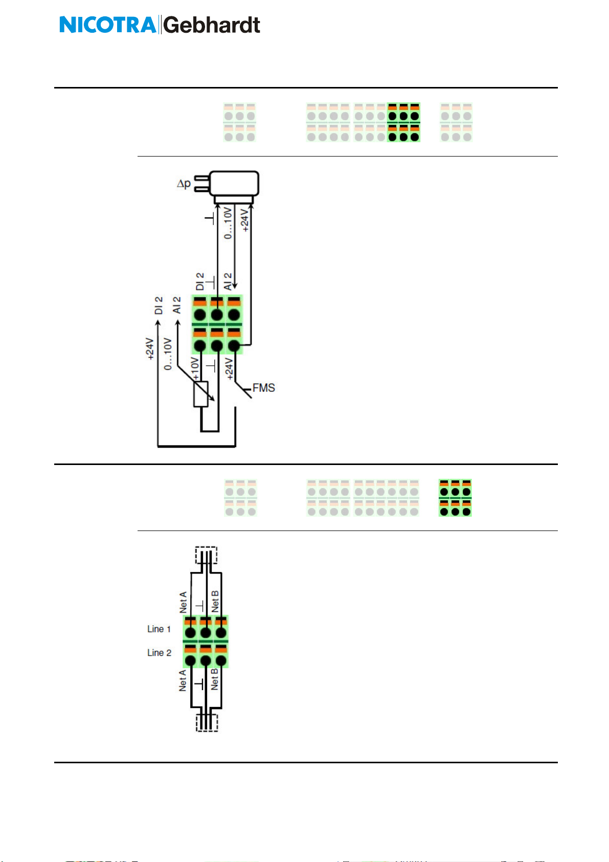
BUS Lines
Line 1
Connect up to 100 subscriber with RS485
Interface
Line 2
Connect up to 100 subscriber with RS485
Interface
WARN NG!
Handling of unused P Ns according to
specification of applied EC-fan supplier!

Operating Manual “FAN Commander 200” ECE 03-0200-5E-MG Seite 14 on 24
4.3.4 Connection Example
Group 1 – closed loop control pressure
3 fans at line 1
Sensor signal p as 0…10V and 24V(=) power supply
Extern enable of closed loop controller by FMS
Group 2 – speed control by potentiometer
2 fans at line 2
Potentiometer for speed setting by 0…10V
Internal enable of control
General connection
day/night - shift – external timer
Utilization error/new error by costumer FMS with external 24V (~) supply
Operating Manual “FAN Commander 200” ECE 03-0200-5E-MG Seite 15 on 24
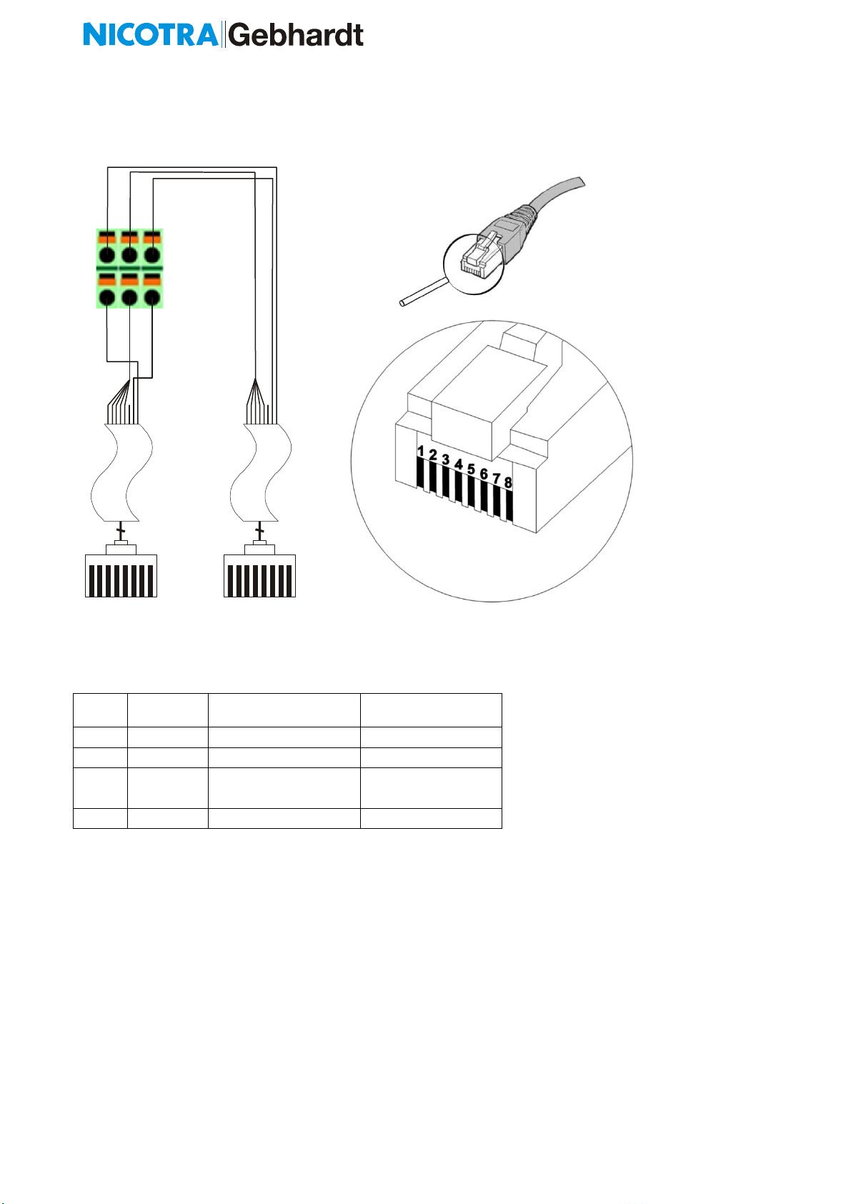
4.3.5 Wiring of Nicotra Gebhardt FFU Controller
Terminal assignment
Wire
Function
colour T A 568B
(mostly Germany)
colour T A 568A
(mostly USA)
1 Net A white / orange white / green
2 Net B orange green
3 Not
used
white / green white / orange
4-8 Ground All other wires All other wires
( iew to the RJ45 plug from front to the contacts)
1 2 3 4 5 6 7 8
1 2 3 4 5 6 7 8
8
8
1
1
8
8
Line 1
Line 2
Net A Net A
Net B Net B
GND GND
Operating Manual “FAN Commander 200” ECE 03-0200-5E-MG Seite 16 on 24
5 Working with the FC 200
5.1 Software
Display
Scan Line Network scan to find all connected de ices with the
chosen protocol
Single Monitor Cyclic scan of single de ice and monitoring of
requested data
Single Control
Control of a single addressable de ice with feedback
Group Control
Control of all fans assigned to one of 20 speed control
groups
Broadcast
Control / Parameterizing of all connected de ices
without feedback (broadcast)
Group Building
up to 20 groups (free definition) for simple speed control and
up to 2 groups for closed loop control mode
Internal PI-Controllers (2) two separate closed loop control circuits
free programmable as temperature, elocity, pressure and %
fixed assigned sensor signal inputs (1/2) and digital inputs
(1/2) to each closed loop control group (1/2)
Error Output as error indication signal and free configurable signal outputs
(high/low acti e) maximum 60V – 500mA
Error 1 red
for acknowledged, but still existing faults
Error 2 red alternating
for new, unacknowledged faults
Operating Le els
3 operating le els (Monitor / Operator / Administrator)
Timer Programmable Scheduler for set-point shift of single fans and
assigned groups

Operating Manual “FAN Commander 200” ECE 03-0200-5E-MG Seite 17 on 24
5.2 Commissioning
5.2.1 Quick Commissioning – fan driven by speed setting
required: Connection Power supply (24V) / Bus (NetA/NetB)
Mainmenu
Suble el 1
Suble el 2
Suble el 3
1. „Login“ as Administrator
default password „0000“
2. „Database“
used Bus Line (1/2) „Config Line“ choose rele ant Bustyp
„nstall Fan“
„Scan Line“ Found de ices will be installed automatically –
correct fan addressing required!
3. „Configuration“
choose – Single / Line / Group / All
max. speed checked or set correctly
4. „Control“
choose – Single / Line / Group / All
„Speed Day“ set day speed in %
„Start Fan“ Start Control
5.2.2 Quick Commissioning – fan driven by closed loop control
required: Connection Power supply (24V) / Bus (NetA/NetB) / Sensor AI (0…10V)
1. „Login“ as Administrator
default password „0000“
2. „Database“
used Bus line (1/2) „Config Line“ choose rele ant Bustyp
„nstall Fan“
„Scan Line“ Found de ices will be installed automatically –
correct fan addressing required!
„Assign group“ assign (fan) group ( 1 …10) for closed loop control
0 = none group
3. „Configuration“
choose – Single / Line / Group / All
max. speed checked or set correctly
4. „Controller“
„Config Controller“ choose Controller 1 or Controller 2 (acc. connection
of sensor to AI1 or AI2)
„Group“ assign under #2 defined fan group to Controller
if needed adapt further controller settings
„Control Controller“
choose Controller 1 or Controller 2
„Set Day“ Set Control alue in %
„Start Controller“ Start Controller with “Day-setting”

Operating Manual “FAN Commander 200” ECE 03-0200-5E-MG Seite 18 on 24
6 Technical Data
6.1 Connection
Power Supply 24V (=)
Current Consumption maximum 100mA
rating according load of 24V (=) i.e. by sensors
Connection plugs
Serie
Wire cross section
Wire cross section (AWG)
Cage Clamps
Phoenix FMCD 1,5/ x-ST-3,5
min. 0,2mm
2
/ max. 1,5mm
2
(solid and stranded)
min. 0,25mm
2
/ max. 1,5mm
2
(stranded with ferrule without
plastic collar)
min. 0,25mm
2
/ max. 0,75mm
2
(stranded with ferrule
with
plastic collar)
min. AWG/kcmil 24 / max. AWG/kcmil 16
6.2 Housing
Variation
Wall- ounted with lid
Fibox Cardmaster PC 1716-l3TT
Counter-Sunk
OKW
NEG TYP A 144x72
Dimensions (LxBxH) 166 x 160 x 100mm
144 x 72 x 129nn
Weight appr. 700g
appr. 500g
Protection Class
(DIN EN 60529)
IP65
IP20
Material
Polycarbonate
(UL 94-5V)
Noryl
(UL 94 V-0)
Protection Class (electrical)
(DIN EN 61140)
III
(Safety Extra Low Voltage)
No Protecti e Earth
III
(Safety Extra Low Voltage)
No Protecti e Earth
6.3 Ambient Operating Conditions
usage indoor application
Temperature 0°C … 40°C (32 … 104°F) - Operating
-20°C … 70°C (-4°F … 158°F) - Storage
relati e humidity 0 … 90%, non-condensing

Operating Manual “FAN Commander 200” ECE 03-0200-5E-MG Seite 19 on 24
6.4 N/- and OUTPUTs
Digital Inputs DI
(day/night; enable group)
+24V DI (Voltage)
10mA (minimum current source capacity)
4 kV (isolating oltage against internal circuit)
Analogue Inputs AI
(Sensor values-, Speed
setting)
0 … 0.5 … 10V (=)
from 0.5V linear
40 k
(internal resistance)
3,75 kV
(isolating oltage against
internal circuit)
Digital Outputs DO
(Error relays)
as low-acti e or high-acti e programmable
60V (max. Voltage as peak AC / DC)
500mA (max. Current as peak AC / DC)
1,5 kV (max. Current as peak AC / DC)
Analogue Outputs AO
Sensor Power Supply
+10V (=)
20mA (max. Current as peak AC / DC)
+24V (=)
100mA (max. Current as peak AC / DC)
min 1kV (isolating oltage across DC/DC con erter)
6.5 Fan Network
Hardware RS485
Maximum Subscriber 200 at 2 Lines
(100 / Line)
Maximum line length 400m (per Line)
Baud rate according type of subscriber
cable (recommended) Cat. 5
isolating oltage against
internal circuit
2,5 kV (o er oltage class 2)
0,5V
0,5V
U
a
nalogue
U
inp
10V
10V

Operating Manual “FAN Commander 200” ECE 03-0200-5E-MG Seite 20 on 24
7 Additional Hints
7.1 Manufacturing
All de ices of the FC 200 series are manufactured according
D RECT VE 2011/65/EU on the restriction of the use of certain hazardous
substances in electrical and electronic equipment
7.2 Packing and Shipping
The shipping is in fitting indi idual packing.
For export the FC 200 is categorized to the following HS code
85176200
Machines for the reception, con ersion and transmission or regeneration of oice,
images or other data, incl. switching and routing apparatus (excl. telephone sets,
telephones for cellular networks or for other wireless networks)
All claims for damage must be reported immediately.
7.3 Service
Technical queries about the FC 200 under:
Nicotra Gebhardt GmbH
Gebhardtstraße 19-25 Telephoneon: +49 (0)7942 / 101 - 0
74638 Waldenburg
Table of contents
Other Nicotra Gebhardt Controllers manuals


