Nielsen-Kellerman SpeedCoach XL2 User manual

www.nkrowing.com.au
1
The Most Relied-Upon
Pocket Weather Instruments
in the World
Making Work & Play
Easier & Safer
Thank you for purchasing this SpeedCoach wiring system. PLEASE take a moment to review these instruc-
tions before installing the wiring harness and impeller. Your SpeedCoach system should provide you with
years of trouble-free service but we are always here to help if a problem arises. To order parts or
accessories or obtain technical support, please call 02 6553 2473. You may also e-mail questions to our
support repre-sentatives at [email protected] or visit NK online at www.nk.com.au
If you've never done this before, please read through all of these installation instructions
before permanently installing any part of your SpeedCoach System.
The VHB ("Very High Bond") mounting tape used in this installation requires 24 hours to
cure to its full bond. PLEASE avoid getting it wet (in other words, don't take your boat for a
row) until fully cured. Failure to do this risks loss of your brand new impeller, or having to
re-install parts of your system.
Wherever you will be installing VHB mounting tape, make sure to use the provided
alcohol swabs to clean all oil and dust from the mounting surfaces. Avoid touching the
VHB with your fingers as the oil on your skin decreases the bond strength.
IF you ever need to remove installed VHB, use a hair dryer to warm the VHB thoroughly,
then peel very slowly from one edge to avoid damaging the surface.
NK Rowing Electronics Warranty & Service
NK does not believe in "disposable electronics." We know our products don't lead a pampered life, and
we design them for years of performance in tough conditions. We guarantee every NK product to be free
of defects in materials and workmanship for a period of TWO YEARS from your date of purchase. We will
repair or replace any defective product or part when notified within the warranty period, and will return the
product via domestic ground shipping at no charge.The following issues do not result from a manufacturing
defect and are not covered under this warranty: damage due to improper use or neglect, including corrosion;
impact damage; modifications or attempted repairs by someone other than an authorized NK repair agent;
normal wear and tear; failed batteries. NK wants you to be an NK customer for life, so we take care of you
even beyond the terms of the normal product warranty with our Customer Care Program. Trade-in any NK
display unit, no matter the age or condition, and receive a generous discount on the replacement product.
Visit www.nk.com.au at any time for detailed product specifications & troubleshooting guides.
SpeedCoach®
Wiring Installation Instructions
suit SpeedCoach Red, Gold & XL
NIELSEN-KELLERMAN
206 Cowans Lane, Oxley Island NSW 2430
Phone: 02 6553 2473
Fax: 02 6553 2544
Email: [email protected]
www.nk.com.au

www.nkrowing.com.au
2
SELECTING AN INSTALLATION LOCATION AND MOUNTING BRACKET
SpeedCoach for a Rower:
It's a good idea to think about where you want your SpeedCoach while you are sitting in your boat.Your mounting location
should allow you to see the unit clearly and reach the top and bottom buttons, but still keep the unit out of the way of your
hands, oar handle or paddle throughout the stroke. If you are using a SpeedCoach XL2 or XL4, make sure that you will be able
to put the unit with the heart rate plug and/or antenna attached in the docking station without obstruction. There are four
common mounting locations:
• On the footstretcher plate between the shoes. This location is by far the most common and will generally require the use
of a T-Bracket to raise the SpeedCoach above the end of your shoes. A few rowing shells are now equipped with an extended
footplate that provides a mounting location without the T-bracket.
• On top of a wing rigger. A wing rigger usually prevents access to the footstretcher mounting location. The SpeedCoach is
mounted in this location with an Angle Bracket attached with Dual-Lock tape to permit the bracket and wires to remain with
the boat when the wing rigger is removed.
• On top of the deck. The SpeedCoach is mounted in this location with an Angle Bracket. Note that the Angle Bracket is
shipped with Dual-Lock tape pre-installed. If desired, this tape may be peeled off and replaced with VHB mounting tape for a
permanent installation on the deck.
• On the cockpit washboard or wall. In some boats, you may wish to mount your unit directly to the stern-most wall of the
cockpit.The dock may be attached directly to the cockpit wall with no mounting bracket, or a T- Bracket may be used to raise
the unit up.
SpeedCoach for a Coxswain:
In the coxswain's seat, the SpeedCoach will generally be used with a Cox-Box or Cox-Vox audio system. In most boats, there is suf-
ficient room on the footrest next to the Cox-Box cup bracket. The mounting dock can generally be secured directly to the deck
without the use of a mounting bracket. In a bow-coxed shell, be sure to choose a mounting location that will not obscure the
coxswain's already limited view. Bow-coxed shells vary widely in their configurations, so you may need to be creative in finding a
mounting location. Both the T-Bracket and Angle Bracket are made of aluminum, and will permit some careful bending to accom-
modate other mounting positions. Be careful not to bend the bracket more than once, or the metal will fatigue and break.
INSTALLING THE MOUNTING BRACKET (IF USED)
The SpeedCoach wiring is shipped with no mounting bracket attached to allow you the flexibility to choose your mounting
option. Make sure you have purchased the correct mounting bracket for the installation option you have chosen. To install
the bracket, clean the mounting location thoroughly with an alcohol prep pad, peel
the liner from the Dual-Lock or VHB tape, align the bracket on the mounting location,
and press firmly.
Install the T-Bracket:
The pre-drilled holes in the T-Bracket are designed to allow easy installation of the
bracket onto the bolts that are used to adjust the height of the footstretcher shoe
plate. To mount in this location, simply remove one of the bolts, slide the mounting
bracket onto the bolt in front or behind the plate, and replace the bolt.
If there is not a bolt already on the footstretcher that you can use, you may need to
drill holes in the footstretcher and secure the docking station with a stainless steel
bolt and nut or screw(s). Be sure your footplate is a solid material if you are using
screws. It may be necessary to insert a small shim behind the stem of the T-Bracket
to support it.
To mount the T-Bracket onto the washbox or cockpit wall, you may use VHB tape
to avoid making holes in your boat. Try to maximize the contact area for the VHB
as the stem of the mounting bracket takes a good deal of force when clicking the
SpeedCoach into the mounting dock.
Install the Angle Bracket:
The Angle Bracket is designed to be mounted to the top of a wing rigger or the deck.
The Dual-Lock tape allows you to remove the docking station from the wing rigger
when you derig your boat. It's easiest to leave both pieces of Dual-Lock attached to the bracket when making the installa-
tion..

www.nkrowing.com.au
3
INSTALLING THE SPEEDCOACH DOCK
Next you will mount the plastic dock on the end of the SpeedCoach wiring to the front of the installed mounting bracket or directly
to the mounting location chosen.If installing the docking station on a T-Bracket,you may use a cable tie to secure the harness wires
so they will stay out of the way when you are strapping your feet into your shoes.
1) Clean the mounting location thoroughly with an alcohol prep pad.
2) Peel the liner from the VHB tape on the wiring dock;
3) Align the dock on the mounting bracket or location and press firmly. Be sure to support the mounting bracket from behind
while pressing the dock into place.
MOUNTING THE SPEEDCOACH
Slide the SpeedCoach display unit onto the docking station until it clicks. Be
sure that the lanyard is out of the way.
NOTE: To prevent the loss of your SpeedCoach in the event that it is bumped
while you are rowing, loop the lanyard around the top of the T-bracket or some
part of your shell and slip the SpeedCoach through the loop. (The lanyard is
designed specifically for this purpose.)
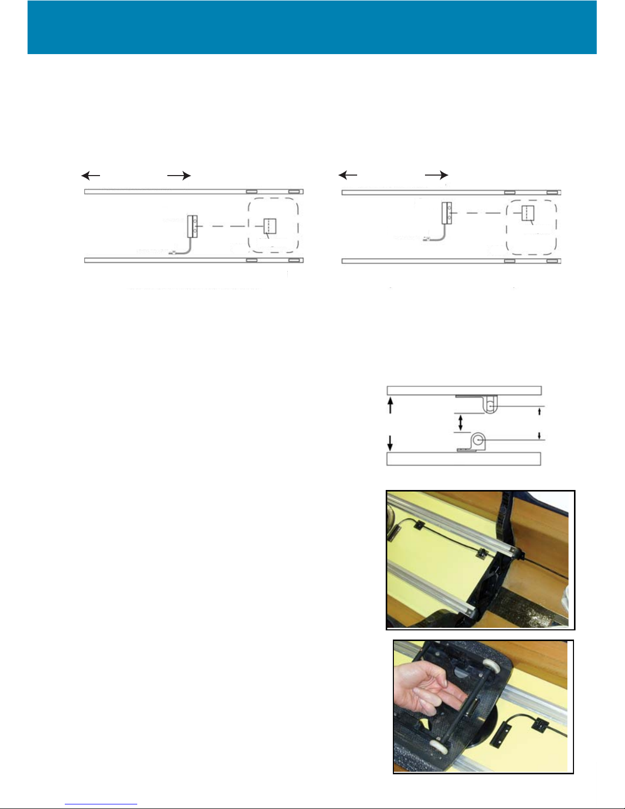
INSTALLING THE SEAT MAGNET & RATE SENSOR
The seat magnet and rate sensor work together to measure your rating while rowing.The magnet must pass within ¾" of the
sensor in order to register a rating, so it is important to make sure that the seat magnet and sensor are installed correctly.
The SpeedCoach can measure stroke rate without using the rate sensor by measuring the changes in boat speed throughout
the stroke. To enable this feature, place the unit in 0-Stroke Mode, and make sure that you have an impeller on the boat. The
stroke rate will not be as consistent or stable as with a seat sensor, but this method can be used as an alternative to the seat
magnet and rate sensor (or as a troubleshooting test when your rate is not working properly.)
Install the Rate Sensor (Black Sensor):
Refer to Figures 1a and 1b. Note the position of the sensor - it should be close to the center of the seat travel and it MUST be
perpendicular to the long axis of the shell.
It is not necessary for the sensor and magnets to be centered between the rails as shown in Figure 1a. They may be positioned
off center as shown in Fig 1b. However, the holes in the magnet assembly MUST pass directly over the holes in the sensor. The
dashed horizontal line in each figure indicates the correct alignment.
PLEASE NOTE: The sensor needs to be installed at the center of the seat travel. If the sensor is too close to either end of the
seat travel, the SpeedCoach may indicate ONE-HALF the correct stroke rate.
www.nkrowing.com.au
4
The vertical spacing between the stroke sensor and the magnet assembly is critical. If the magnet passes too far from the
sensor the sensor may fail to register every stroke, resulting in low readings. If the magnet is too close to the sensor, it may
strike the sensor and knock one or both out of place.
Because the distance between the seat plate and the deck varies considerably from shell to shell, you should start by measur-
ing this distance. Refer to Figure 2.
1/2 Distance
of Seat Travel
FIGURE 1a: SENSOR & MAGNET INSTALLATION
(Sensor Installed on Centerline of Seat)
Sensor
Magnet
Cable Clip Seat
1/2 Distance
of Seat Travel
FIGURE 1b: SENSOR & MAGNET INSTALLATION
(Sensor Offset Centerline of Seat)
Sensor
Magnet
Cable Clip
Seat
- If the distance measured as in Figure 2 is between 22mm and 28 mm, you may mount the sensor and magnet with no
further adjustment.
- If the distance measured as in Figure 2 is GREATER than 28 mm, you will need to make a spacer of appropriate thickness.
You may choose to shim the sensor or the magnet; whichever is easier. DO NOT use any magnetic material for your shim.
Many boat builders have shims designed to fit their particular seats.
- If the distance measured in Figure 2 is LESS than 22 mm, the magnet
and the sensor will interfere.Try mounting the magnet on the upper side
of the seat plate or the sensor on the underside of the deck. As a last
resort, you will have to remove material from either the seat or the deck
(this almost never needs to be done).
Check that the sensor cable is routed conveniently before mounting the
sensor.You can install the sensor and magnets semi-permanently by using
the 3M VHB (Very High Bond) tape supplied. Should you wish to make a
temporary installation, use electrical tape to affix the sensor. Use the alcohol
prep pad provided to clean the area of the deck to where you will attach the
sensor. Peel away the protective layers of the VHB double-sided tapes, and
firmly press the sensor onto the cleaned area of the deck.Wait 24 hours before
rowing to allow the VHB tape to fully cure.
Using the provided cable tie mounts, secure the sensor wire. If in the future
you need to remove the wire, simply cut the cable tie and later use a new one
to secure the wire.
Install the Magnet:
1) Remove and inspect the seat plate to find an appropriate place to mount
the magnet.
2) Clean the mounting location thoroughly with an alcohol prep pad.
3) Peel the liner from the VHB tape on the magnet.
4) Align the magnet on the mounting location and press firmly.
5) Return the stroke seat to its slide and check that the clearance between the
magnet and sensor is no more than 10 mm (refer to Fig 2). Check also that the
magnets pass directly over the sensor (refer to Figures 1a, 1b).
NOTE: On seats without a sliding carriage (such as shown in the photo), there
may be no seat plate for attaching the magnet. One option in this instance is to
place the flange of the magnet assembly on top of the axle tube and secure the
magnet with a few wraps of electrical tape.
FIGURE 2: SENSOR & MAGNET SPACING
Seat Plate
Deck
Sensor
Magnet
1 1/8" Max
7/8" Min 3/8" Max 3/4" Max
Center-to-Center

www.nkrowing.com.au
5
INSTALLING THE HEART RATE SENSOR
SpeedCoach XL2 and XL4 display units can measure heart rate when the heart rate sensor is installed and a chest strap is worn.
The ideal location to mount the sensor is on the side of the boat,in line with the stroke rate sensor and oriented perpendicular
to the stroke rate sensor.Try to mount the sensor so that the chest strap always remains within 1 m of the sensor.
NOTE: At present, NK can only guarantee interference-free readings for XL heart rate monitors when there is only ONE chest-
belt transmitter within a 2 m range of the heart rate sensor at any time. As a result, it is possible to use two monitors in most
pairs or doubles by placing the stroke seat sensor close to the stern end of the seat deck, and the bow-seat sensor close to the
bow end of the deck. In larger shells, the monitors and sensors will need to be at least two seats apart (i.e. at 2 and 4 seats, not
at 2 and 3 seats). In larger team boats, it is likely that heart rate systems in adjacent seats will interfere with each other. (This
includes having a rower wear a personal heart rate monitor in a seat adjacent to a rower using an XL2.)
Install the Heart Rate Sensor:
1) Clean the mounting location thoroughly with an alcohol pad.
2) Peel the backing off the pieces of velcro on the heart rate sensor;
3) Press the sensor firmly onto the deck.
4) Secure the wire with the cable tie mounts. If in the future you need to remove the
wire, simply cut the cable tie and later use a new one to secure the wire.
INSTALLING THE SPEED SENSOR & IMPELLER
All boats produce a boundary layer of turbulent water from the bow to the stern.The closer you get to the stern,the more turbulent
the water. The SpeedCoach unit is factory calibrated for correct readings with the impeller installed at 5 meters from the bow of
the boat.This location will typically fall under the footstretchers of a single, or around two seat of a larger boat. Installing the impel-
ler in this location should yield accurate performance even if you don't calibrate your unit.You should avoid placing the impeller
farther than 6 meters from the bow because the water will be too turbulent for the impeller to spin consistently, so accuracy will
be compromised - even if calibrated. (See "CALIBRATION" section for instructions on how to calibrate.)
Stern
Impeller
Bow
5m (16' 3")
Select the Impeller and Sensor Location:
- You DO NOT need to drill holes through the hull of the boat to install the impeller and sensor. The sensor mounts to the
inside of the boat, above the impeller, and communicates wirelessly through the hull. While the impeller does not need to be
on the centerline, it must be submerged (if NOT centered be sure to still align the sensor accordingly with the movement of
the boat).
- Measure 5 meters from the bow of your boat, and inspect your boat to select a mounting location for the impeller. Make
sure to select a location where you will be able to mount the speed sensor directly above the impeller. Avoid sealed bulkheads,
ribs and footstretchers.The impeller does not need to be on the exact midline of the boat, but must stay submerged. Keep the
impeller parallel with the keel to minimize drag and steering effects.
- The impeller can be mounted permanently with the included VHB tape, or temporarily with electrical or packing tape. If
you are planning on removing the impeller, you may wish to mark the location with permanent marker so you do not have to
measure when you re-install.
Install the Impeller (Semi-Permanent):
1) Set the impeller on top of the hull in your selected location. Sight down the length of the hull to ensure the impeller is straight.
Mark your mounting location with a permanent pen.

www.nkrowing.com.au
6
2) Clean the mounting location thoroughly with an alcohol prep pad (being careful not to remove your marks).
3) Peel the liner from one side of the VHB tape and align the VHB tape with your marks and smooth in place.
4) Peel the remaining liner from the VHB tape.
5) DOUBLE CHECK (it's easy to make a mistake here) that you have the curve of the impeller pointing toward the bow ball, and the
impeller pointing toward the fin.
6) Align the impeller on the VHB tape and press firmly.
7) WAIT 24 HOURS BEFORE ROWING. The tape requires
24 hours to fully cure!
Install the Impeller (Temporary):
For borrowed boats, or if you plan to remove your
impeller for racing, you may install your impeller tem-
porarily with electrical tape. When installed properly
with electrical tape, the impeller should not easily
fall off your boat. However, check the tape regularly to make sure that it is still
secured to the boat and is not beginning to peel off.
1) Set the impeller on top of the hull in your selected location. Sight down the
length of the hull to ensure the impeller is straight. Mark your mounting loca-
tion with a permanent pen.
2) Clean the mounting location thoroughly with an alcohol prep pad (being care-
ful not to remove your marks).
3) CUT (do not tear - this stretches the adhesive and makes it less effective) two
pieces of electrical tape approximately 180 mm long.
4) Place the impeller in its mounting location. DOUBLE CHECK (it's easy to
make a mistake here) that you have the curve of the impeller pointing toward
the bow ball, and the impeller pointing toward the fin.
5) Lay one long pieces of electrical tape on either side of the impeller, with approximately half of the width of the tape on the
impeller mount flange and half on the hull. You should have approximately an inch of extra tape on each end that will affix
solely to the boat.
6) Cut two 65 mm pieces of tape for the two ends of the impeller. Lay them on top of the ends of the mount flange,and across
the two long pieces of tape
7) Smooth all the tape thoroughly, ensuring there are no bubbles and full contact with the hull.
8) WAIT 24 HOURS BEFORE ROWING.
IMPORTANT!
While transporting your boat, it is important to secure or remove the impeller. The constant spinning will wear the magnet.
You can either keep a cover on your boat while transporting, tape the impeller so it cannot spin, or unscrew the impeller from
the hull mount.
.
Pickup
Impeller
Side View
Side View
Impeller
Pickup
Top View
Top View
OR

www.nkrowing.com.au
7
Install the Speed Sensor (Blue Sensor)
The SpeedSensor, which is the blue sensor provided, should be as close to the impeller as possible. You install the
SpeedSensor inside the hull (i.e. the opposite side from the impeller). The SpeedSensor can either be installed perpendicu-
lar to the impeller when positioned directly above it, or parallel to the impeller when it is located one impeller length
in front or behind of the actual impeller. Although inside the hull, the SpeedSensor still must be fixed securely to the
shell. Make sure you clean the surface well before taping it to the boat.
1) Clean the mounting location thoroughly with an alcohol prep pad.
2) Peel the liner from the VHB tape on the blue sensor.
3) The SpeedSensor can either be installed perpendicular to the impeller when positioned directly above it, or parallel to
the impeller when it is located one impeller length in front or behind of the actual impeller.
IF MOUNTING THE SENSOR PARALLEL TO THE IMPELLER, DO NOT ALIGN THE SENSOR DIRECTLY ON TOP OF THE IMPELLER.
4) If desired, secure the wires using cable ties and mounts. If youhave extra wire, coil the wire and secure with a cable tie.
NOTE: Multiple sensors can be mounted around one impeller, simply mount them next to each other, or stack them on top of
each other. (i.e. if you have a mounting harness in both seats of a double.)
CALIBRATION
Calibration is an optional step that allows the display unit to compensate for different impeller locations and variations in hull
shapes. If you need very accurate distance and speed measurements (to compare your performance with published results,
for instance), calibration is a good idea. However, even if your unit is not properly calibrated, your SpeedCoach will provide you
with valuable feedback on changes in boat speed, and you will be able to compare upstream and downstream pieces.
Your SpeedCoach has a factory calibration value of 1.000. To calibrate your system, you will be determining a new calibration
value by comparing your SpeedCoach's distance reading with a known distance reading. On still water, row or paddle over
your measured distance and record the distance displayed on your SpeedCoach. On flowing water, row or paddle over your
measured distance both up and down stream and average the results shown on your display. Then, use the following formula
to obtain your new calibration value.
(CURRENT CAL VALUE)(TRUE DISTANCE) = NEW CAL VALUE
DISPLAYED DISTANCE
For example, if you know you covered 1 mile, but your display shows 0.92, your calibration value will be:
(1.000)(1.00) = 1.086
0.92
PLEASE NOTE: Calibration is boat and impeller location-specific: if you move your unit to a new boat, or modify the location of
your impeller, it is recommended that you recalibrate the unit.
TROUBLESHOOTING
Please refer to our product specific trouble shooting guides.
These can be downloaded from www.nkrowing.com.au

www.nkrowing.com.au
8
Contact Info
Nielsen Kellerman Australia Pty Ltd
Delivery Address
(Please send all parcels to this address)
206 Cowans Lane
Oxley Island NSW 2430
Email: [email protected]om.au
Web: www.nk.com.au
Phone: 02 6553 2473
Fax: 02 6553 2544
Authorised reseller:
Revised 1 June 2014
This manual suits for next models
1
Table of contents
Other Nielsen-Kellerman Heart Rate Monitor manuals


