Nikko STA7070 User manual
am-fm-multiplex
stereo
receiver
model
sta
7O'7O
owner's
manual
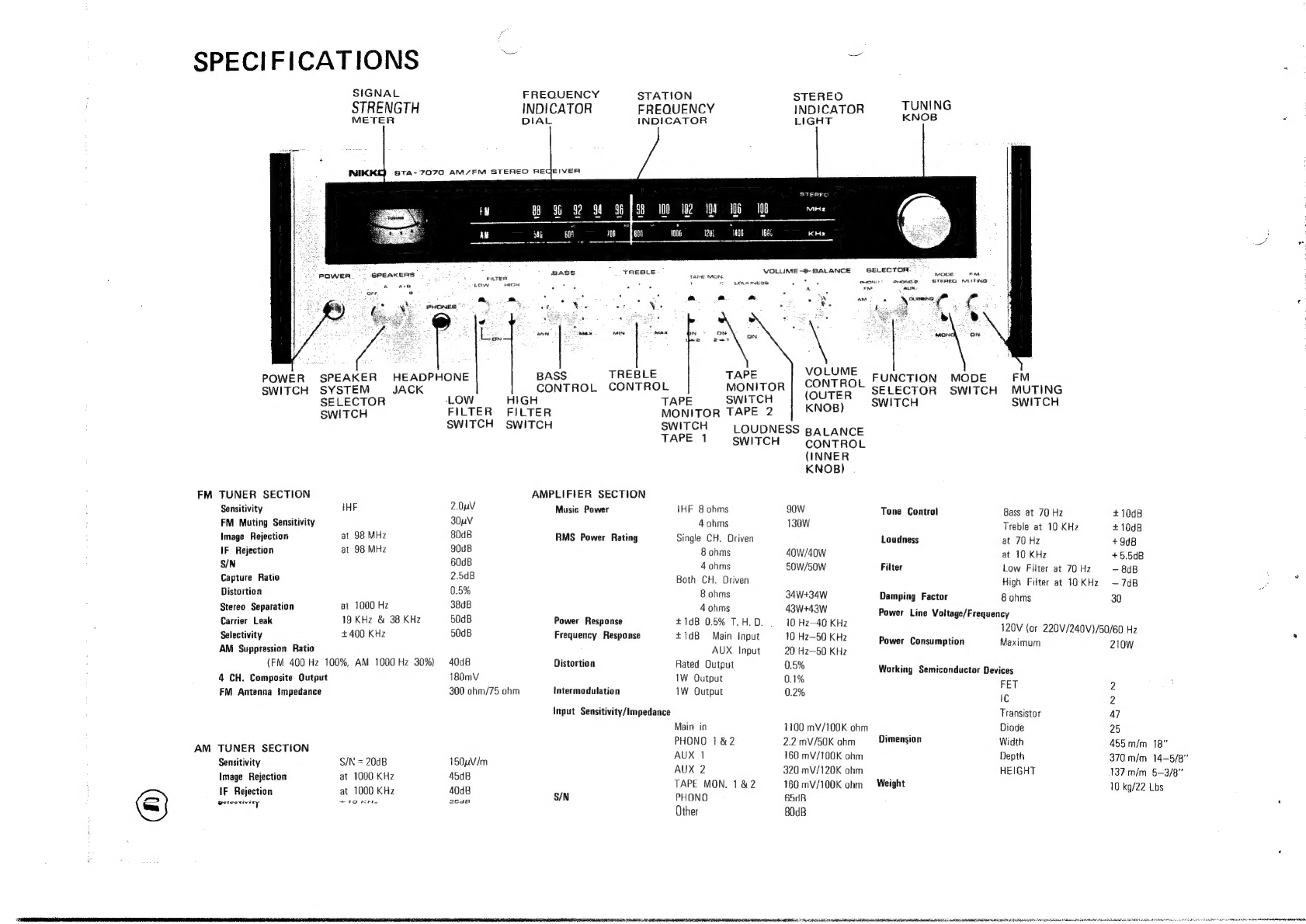
SPECIFICATIONS
Se
SIGNAL
FREQUENCY
STATION
STEREO
STRENGTH
INDICATOR
FREQUENCY
INDICATOR
TUNING
METER
DIAL
INDICATOR
LIGHT
KNOB
STA-
7070
AM/FM
STEREO
AEGEIVER
STEREC
100
102
108
‘006
bi
‘i
uses
sf
18.
SELECTOR:
MODE
FM.
STERED
MUTING
{.
TREBLE
BASS
VOLUME
-®-
BALANCE
PLTER
TAPE
MON.
Low
aise
*
A
,
2
LOUONESS:
.
‘
PHONG?
* 7 °
*.
em
PAaWwER
SPEAKERS
-
:
PHONG?
AUX.
Ayovenene
wv
:
A
Ate
ore,
8
x
a.
ms,
PHONES
%
;
5
Nag
<
EES
.
:
;
F
eS
ads
ee
a
=
Fee
‘ON
q
ce
am
ON,
aM
.
VOLUME
P
R
PEAKER
HEADPHONE
BASS
TREBLE
TAPE
M
SWITCH
SYSTEM
JACK
CONTROL
CONTROL
MONITOR
|
CONTROL
Ce
ON
eH
ae
SELECTOR
LOW
HIGH
TAPE
SWITCH
(OUTER
cwitcH
SWITCH
SWITCH
FILTER
FILTER
MONITOR
TAPE
2
|
KNOB)
SWITCH
SWITCH
SWITCH
LOUDNESS
BALANCE
TAPE
1
SWITCH
=
CONTROL
(INNER
KNOB)
FM
TUNER
SECTION
AMPLIFIER
SECTION
Sensitivity
iHE
2.0nV
Music
Power
iHF
8
ohms
gow
Tone
Control
Bass
at
70
Hz
+1008
FM
Muting
Sensitivity
30uV
4
ohms
130W
Treble
at
10
KHz
#1048
Image
Rejection
at
98
MHz
80dB
RMS
Power
Rating
Single
CH.
Driven
Loudness
at
70
Hz
+908
IF
Rejection
at
98
MHz
90dB
8
ohms
40w/40w
at
10
KHz
+5,5d8
S/N
60dB
4
ohms
50W/50W
Filter
Low
Filter
at
70
Hz
-
BdB
Capture
Ratio
2.508
Both
CH.
Driven
High
Filter
at
10KHz
—7d8
Distortion
0.5%
8
ohms
34W+34W
Damping
Factor
8
ohms
30
Stereo
Separation
at
1000
Hz
38dB
4
ohms
43W+43W
Power
Line
Voltage/F
Carrier
Leak
19
KHz
&
38
KHz
50dB
Power
Response
+10B
0.5%
T.H.D.
10
Hz—40
KHz
ge/
en
a
Selectivity
£400
KHz
50dB
Frequency
Response
+1d8
Main
input
10
Hz—-50
KH2
iia
aceteeat
(or
220V/240V)/50/60
Hz
AM
Suppression
Ratio
AUX
Input
20
Hz~50
KHz
ption
aximum
210W
(FM
400
Hz
100%,
AM
1000
Hz
30%)
408
Distortion
Rated
Output
5%
A A
:
AG
Gila
oie
Boia
ay
cai
a
Working
Semiconductor
Devices
FM
Antenna
!mpedance
300
ohm/75
ohm
intermodulation
1W
Output
0.2%
i
:
Input
Sensitivity/Impedance
Transistor
47
Main
in
1100
mV/100K
chm
Diode
25
AM
TUNER
SECTION
iiss
1&2
ae
Dimension
va
455
m/m
18"
;
Sensitivity
S/N
=
20dB
150uV/m
ee
saan
oOR
ak
anes
370
m/m
eee
Image
Rejection
at
1000
KHz
45dB
pen
AD
iereaMine
he
Weight
es
ee
eee
Doe
as
S/N
PHONO
B5dR
as
Other
80dB

You
have
just
approached
an
exciting
new
dimension
in
music
listening
enjoyment.
With
your
purchase
of
the
Nikko
STA-7070
Stereo
Receiver,you
have
secured
a
measure
of
“Daily
Happiness”
for
yourself
and
your
family.
Nikko,
translated,
means
just
that...
“Daily
Happiness.”
It
is
the
job
of
this
fine
receiver
to
do
some
translating
for
you...
to
take
broadcast
electronic
impulses
and
transform
them
into
the
enveloping
experience
of
music.
To
deliver
soothing...
stimulating...
entertaining
listening
pleasure,
making
everyday
listening
an
enjoyable
event!
This
STA-7070
StereoReceiver
is
a
sophisticated
instrument
.
..
developed
by
some
of
the
world’s
most
creative,
technically
proficient
engineers.
This
Nikko
Receiver
is
the
product
ot
one
of
the
world’s
leading
electronic
component
manufacturers!
The
Nikko
STA
~
7070
is
designed
to
achieve
tne
ultimate
in
stereophonic
performance,
incorporating
many
of
the
latest
technological
advances:
Field
Effect
Transistors
(FET)
Integrated
Circuits
(1.C.)
for
superior
sensitivity.
Triple
Circuit
Breaker
Protection
for
malfunction-free
dependability.
This
manual
has
been
prepared
to
help
you
get
the
maximum
performance
from
your
Nikko
Receiver.
The
step-by-step
“How
To
Operate”
instructions,
Function
Explanations
and
Connection
Diagram
will
add
to
your
knowledge
..
.and
enable
you
to
“tune
yourself
in”...
to
the
many
years
of
“Daily
Happiness”
that
lie
ahead.
PRINTED
IN
JAPAN

ie
EXPLANATION
OF
FRONT
PANEL
®
©
OP
|
@
id
102
Wa
W808
(ete
150
Heo
|
t
{
tS
Acne
pe
ee
subboice
POWER
SWITCH
(#12)
to
the
“DUBBING”
position,
TAPE
1
plays
and
TAPE
2
PHONO
1.
Turn
to
“PHONO
1”
when
playing
manual
or
automatic
Pressing
this
switch
will
permit
the
STA
-
7070
to
operate,
and
records
so
that
duplication
from
TAPE
1
to
TAPE
2
can
be
made.
record
player
equipped
with
magnetic
type
cartridge.
repressing
will
turn
this
receiver
to
“OFF”
9.
TAPE
MONITOR
SWITCH
TAPE
2
PHONO
2.
Turn
to
“PHONO
2”
when
playing
manual
or
automatic
SPEAKER
SYSTEM
SELECTOR
SWITCH
TAPE
DUBBING
SWITCH
TAPE
2-
TAPE
1.
record
player
equipped
with
magnetic
type
cartridge.
OFF:
Turn
to
“OFF”
when
using
headphones.
Push
down
this
switch
to
check
tape
recording
with
headphones,
DUBBING:
When
making
tape-to-tape
duplication,
perform
along
A:
Turn
to
“A”
only
when
operating
A
speaker
system.
(The
tape
recorder
or
deck
should
be
equipped
with
separate
recording
with
TAPE
MONITOR
SWITCH
1:
or
2
turned
on
A+B:
Turn
to
“A+B”
when
operating
A
and
B
speaker
system
and
playback
head.)
When
setting
FUNCTION
SELECTOR
SWITCH
;
as
desired.
simultaneously.
(#12)
to
the
“DUBBING”
position,
TAPE
2
plays
and
TAPE
1
13.
MODE
SWITCH
B:
Turn
to
““B”
when
operating
B
speaker
system.
records
so
that
duplication
from
TAPE
2
to
TAPE
1
can
be
made.
A
mode
switch
to
allow
you
to
select
Monophonic
or
Stereophonic
HEADPHONE
JACK
In
addition
to
tape
monitoring,
4-channel
adaptor
can
be
connected.
operation
to
fit
your
need.
7
Plug
stereo
headphone
cord
into
this
jack
for
private
or
monitoring
In
this
case,
the
switch
must
be
in
the
“ON”
position.
14.
FM
MUTING
SWITCH
|
listening
pleasure,
10.
LOUDNESS
SWITCH
Switch
“ON”
to
eliminate
unwanted
between
station
background
LOW
FILTER
SWITCH
Switch
in
“ON”
position
compensates
for
frequency
loss
at
low
noise.
i
Switch
“ON”
to
eliminate
low
frequency
rumble
noise
from
incoming
voiume
levels.
15.
TUNING
KNOB
;
signal.
11.
VOLUME
CONTROL
(OUTER
KNOB)
By
turning
this
knob,
you
select
the
desired
station
frequency.
a
HIGH
FILTER
SWITCH
For
low
volume,
turn
left;
for
high
volume,
turn
right.
16.
STEREO
INDICATOR
LIGHT
Switch
“ON
to
eliminate
high
frequency
scratch
noise
from
incoming
BALANCE
CONTROL
(Inner
knob):
Click-stops
at
the
top
center
It
lights
up,
to
visually
indicate
STEREO
FM
MULTIPLEX
broadcast
signal.
position.
reception.
BASS
CONTROL
12.
FUNCTION
SELECTOR
SWITCH.
17.
STATION
FREQUENCY
INDICATOR
Click
-
stops
in
5
steps
at
each
of
plus
and
minus
sides.
AUX:
Select
AUX.
1
or
AUX.
2
according
to
the
output
Points
out
station
frequency
received.
TREBLE
CONTROL
level
of
auxiliary
accessory
to
be
used.
Turn
to
18.
FREQUENCY
INDICATOR
DIAL
Click
-
stops
in
5
steps
at
each
of
plus
and
minus
sides.
“AUX”
when
using
other
auxiliary
audio
accessories
Clear
and
easy-to-read
slide
rule
dial
that
indicates
precise
STATION.
TAPE
MONITOR
SWITCH
TAPE
1
such
as
crystal
or
ceramic
type
cartridge,
tape
recorder
FREQUENCY
location.
:
TAPE
DUBBING
SWITCH
TAPE
1—
TAPE
2.
with
peramplifier,
television
output,
etc.
19.
SIGNAL
STRENGTH
METER
Push
down
this
switch
ta
check
tape
recording
with
headphone.
(The
tape
recorder
or
deck
should
be
equipped
with
separate
recording
and
playback:
head.)
When
setting
FUNCTION
SELECTOR
SWITCH
AM:
Turn
to
“AM”
when
receiving
AM
broadcast.
FM:
Turn
to
“FM”
when
receiving
FM
mono
or
multiplex
stereo
broadcast.
When
Turning
Knob
(#15)
is
turned
to
desired
station,
meter
should
show
maximum
reading.

20.
21.
23.
fon
a
780
3.
x
ae
‘s
a
FM
ace
COMPOSITE
OUT
RIGHT
GND
|
PAL
COAXIAL
CABLE
TAPE
2
FEC
/PB
Ne
s000088
000
YAP;
2/6CH
ADAPTOL
OLTI2CH)
INI4CH)
OUT
@
AUX
2
AUX!
PHONO
2
PHONO
|
0)
@
Qd
Oo
|
Sen’
Lert
RIGHT
Lery
~
~
nN
Om
Ome
mOmeCmen.,
PRE OUT
CONNECT
MAIN
a
TAPE
|
REC
/PB
SEPARATE,
oN
Om
TAPE
t
B
SPEAKERS
IN
RIGHT
GND
LEFT
GND
7371850
poooose00008
f
ee
(20)
QI)
22)
GROUND
TERMINAL
Earth
ground
connection
for
RECORD
PLAYER.
INPUT-TERMINALS
AUX-1
HIGH
LEVEL
Should
be
selected
according
to
the
output
AUX—2
LOW
LEVEL
level
of
auxiliary
accessory
to
be
connected.
PHONO
1
Plug
cables
of
manual
or
automatic
record
player
equipped
with
magnetic
type
cartridge
into
these
jacks.
PHONO
2
Plug
cables
of
manual
or
automatic
record
player
equipped
with
magnetic
type
cartridge
into
these
jacks.
(Should
select
PHONO
1.
or
PHONO
2
for
connection).
TAPE
IN/OUT
TERMINALS
TAPE
1.
IN:
Connect
the
output
plug
of
the
tape
deck
into
this
jack
for
playback
of
the
tape
deck
and
TAPE
MONITOR
SWITCH
(#8)
is
in
the on
position
for
monitoring
the
recording
by
the
tape
deck.
QUT:
Connect
the
input
plug
of
the
tape
deck
into
this
jack.
TAPE
2.
IN:
Connect
the
output
plug
of
the
tape
deck
into
this
jack
for
playback
of
the
tape
deck and
TAPE
MONITOR
SWITCH
(#8)
is
in
the
on
position
for
monitoring
the
recording
by
the
tape
deck.
OUT:
Connect
the
input
plug
of
the
tape
deck
into
this
jack.
TAPE
REC/P.B
(DIN
TYPE
CONNECTOR)
TAPE
1
This
connector
is
an
extra
input
and
output
terminal
for
European
type
recorder.
TAPE
2
This
connector
is
an
extra
input
and
output
terminal
for
European
type
recorder.
(Connect
4
-
channel
adaptor
with
TAPE
MONITOR
SWITCH
(#9)
turned
on.)
24.
25.
26.
27.
28.
23)
MAIN
IN/OUT
SWITCH
CONNECT/SEPARATE—
Must
be
set
to
the
“SEPARATE”
position
only
when
connecting
multi-amplifiers
or
4-channel
adaptor.
(See
#25.)
MAIN INPUT/PRE
OUTPUT/FM
4CH
OUT
PUT
TERMINAL
MAIN
INPUT
(R/L):
Main
amplifier
input
terminals;
for
use
when
it
becomes
necessary
to
bypass
the
STA-
7070
pre-amplifier.
This
function
is
ac-
complished
in
conjunction
with
switch
(#24)
located
in
the
rear
of
the
STA-7070
Provides
output
of
pre-amplifier
signals
al
these
terminals
from
the
STA-7070
pre
amplifier.
FM
4CH
OUTPUT:
Connect
FM
broadcast
4-channel
adaptor.
SPEAKER
TERMINALS
(SPEAKER
SYSTEM
B)
A.
Connect
right-side
speaker
cables
to
terminals
“RIGHT”
and
PRE
OUTPUT
(R/L):
“GND”.
B.
Connect
left-side
speaker
cables
to
terminals
“LEFT”
and
“GND”.
C.
"GND"
markings
are
for
correct
phasing
of
both
speakers.
SPEAKER
TERMINALS
(SPEAKER
SYSTEM
A)
A.
Connect
right-side
speaker
cables
to
terminals
“RIGHT”
and
“GND”.
B.
Connect
left-side
speaker
cables
to
terminals
“LEFT”
and
“GND”.
C.
“GND”
markings
are
for
correct
phasing
of
both
speakers.
POWER
SUPPLY
CORD
Connect
this
cord
into
electrical
AC
receptacle.
AM/FM
STEREO
RECEIVER
MODEL
STA-
7070
RATING
AC
$0/BOH2
&
NIKKO
ELECTRIC
MFG
CO.LTO.
MTIEKTON
INOPERATIVE,
PUSH
CRCOUIT
[REAKER,
ye
nem
I
SECONDARY
ral
cara
,
eoeced
TOTAL,
350"
MAX
=
2
a
Ce
}
UNSWITCHED
AC
OUTLETS
$0,
60H:
120V
s20v
210
WATTS
PRODUCT
OF
JAPAN
A
SPEAKERS
RIGHT
GND
oe,
aa
A
29.
30.
31.
32.
33.
34
35.
LEFT
GND
Bz
2O«C«
ih
BC
AC
OUTLET
(Unswitched)
Accessory
power
outlet.
AC
always
available
when
receiver
is
plugged
into
AC
receptacle
and
is
nat
controlled
by
the
Main
Power
Switch
(
#1).
Maximum
capacity
is
350
watts.
AC
OUTLET
(Switched)
This.
outlet
is
connected
to,
and
turned
“ON”
and
“OFF”
by
the
Main
Power
Switch
(#1).
Maximum
capacity
is
100
watts.
CIRCUIT
BREAKER
(Primary)
The
primary
circuit
breaker
protects
the
receiver
from
major
damage
due
to
overload
or
short
circuit.
CIRCUIT
BREAKER
(Secondary)
LEFT
and
RIGHT
outputs
are
protected
against
overload
with
their
respective
circuit
Breaker
provided.
When
the
output
is
unavailable,
press
the
red
reset
buttons.
When
the
circuit
breakers
reoperate
even
after
pressing
the
red
buttons,
the
STA-7070
is
in
trouble.
Check
the
speaker
output
cords
for
short-circuit.
AM
BAR
ANTENNA
Adjust
this
bar
for
optimum
AM
broadcast
reception
with
minimum
noises,
ANTENNA
TERMINALS
FM
—
FM
—
GND
AM
3002
7582
Connect
balance-type
antenna
with
an
impedance
of
300
ohms
to
FM
terminals
and
unbalance-type
antenna
of
75
ohms
to
FM
and
GND
terminals.
75Q
COAXIAL
CABLE
When
the
FM
antenna
is
of
75-ohms
coaxial
cable
type,
the
outer
earth
conductor
of
the
cable
must
be
held
with
this
holder
and
the
inner
conductor
connected
to
FM
terminal.

Se
ope
one
eeragetias
cones
emir
ranma
eee
_
Sone
Ter
MRE
NERO
SRL
AIIIES
IW
OL
Z
YSGHOIZY
3dVL
eects
ema
d19V1dS93u
|
YAq0YOOSY
3dVL
@
AdAL
DILINOVW
|
ONOHd
ATOVLd3S935Y
DV
OL
YAMVAdS
LHOW
@
W3LSAS
adAL
SILANOVW
&
ONOHd
YaMVadS
LHOIY
FIOVLdSOIY
OV
OL
VNNGLNY
WV
VNN3LNV
W4
Meads
La
WVYHSOVIG
NOILOANNOOD
NOOR
WN>
17.
18.
“19.
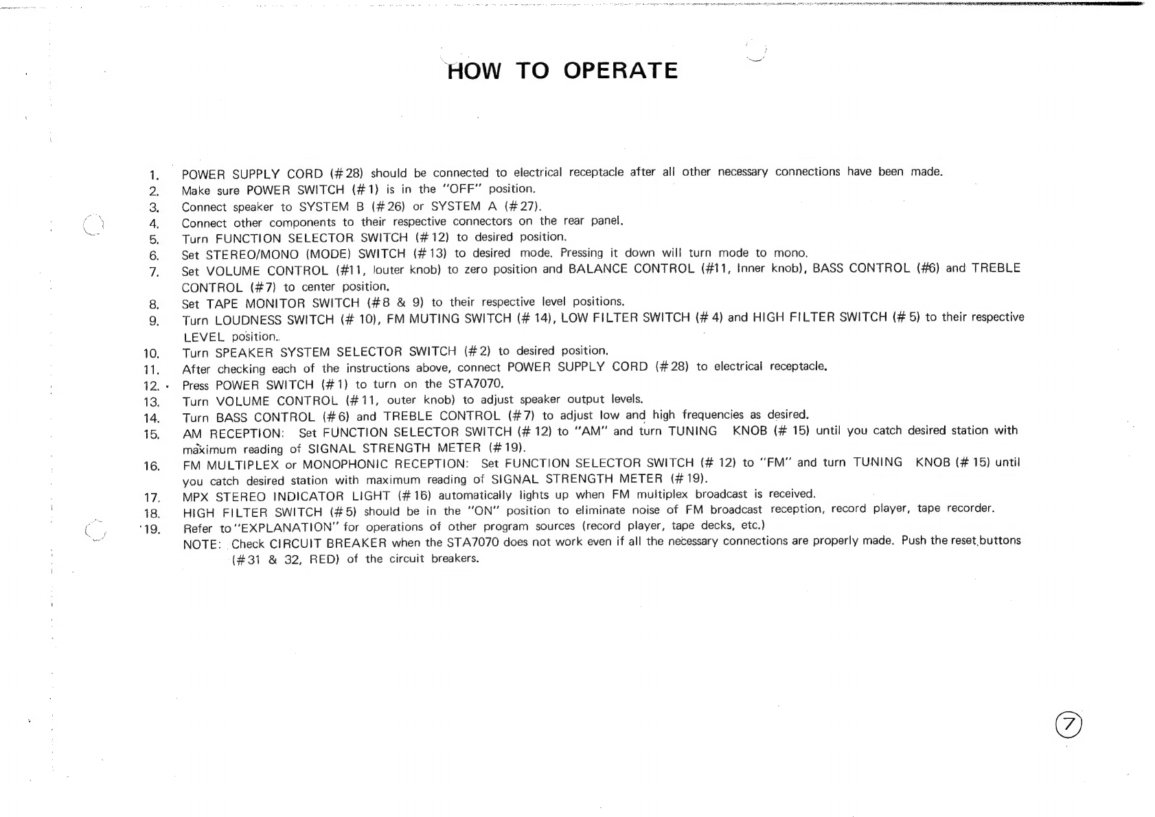
‘HOW
TO
OPERATE
.
POWER
SUPPLY
CORD
(#28)
should
be
connected
to
electrical
receptacle
after
ali
other
necessary
connections
have
been
made.
Make
sure
POWER
SWITCH
(#1)
is
in
the
“OFF”
position.
Connect
speaker
to
SYSTEM
B
(#26)
or
SYSTEM
A
(#27).
Connect
other
components
to
their
respective
connectors
on
the
rear
panel,
Turn
FUNCTION
SELECTOR
SWITCH
(#12)
to
desired
position.
Set
STEREO/MONO
(MODE)
SWITCH
(#13)
to
desired
mode.
Pressing
it
down
will
turn
mode
to
mono.
Set
VOLUME
CONTROL
(#11,
louter
knob)
to
zero
position
and
BALANCE
CONTROL
(#11,
Inner
knob),
BASS
CONTROL
(#6)
and
TREBLE
CONTROL
(#7)
to
center
position.
Set
TAPE
MONITOR
SWITCH
(#8
&
Q)
to
their
respective
level
positions.
Turn
LOUDNESS
SWITCH
(#
10),
FM
MUTING
SWITCH
(#
14),
LOW
FILTER
SWITCH
(#
4)
and
HIGH
FILTER
SWITCH
(#
5)
to
their
respective
LEVEL
position..
Turn
SPEAKER
SYSTEM
SELECTOR
SWITCH
(#2)
to
desired
position.
After
checking
each
of
the
instructions
above,
connect
POWER
SUPPLY
CORD
(#28)
to
electrical
receptacle.
Press
POWER
SWITCH
(#1)
to
turn
on
the
STA7070.
Turn
VOLUME
CONTROL
(#11,
outer
knob)
to
adjust
speaker
output
levels.
Turn
BASS
CONTROL
(#6)
and
TREBLE
CONTROL
(#7)
to
adjust
low
and
high
frequencies
as
desired.
AM
RECEPTION:
Set
FUNCTION
SELECTOR
SWITCH
(#12)
to
“AM”
and
turn
TUNING
KNOB
(#
15)
until
you
catch
desired
station
with
maximum
reading
of
SIGNAL
STRENGTH
METER
(#19).
FM
MULTIPLEX
or
MONOPHONIC
RECEPTION:
Set
FUNCTION
SELECTOR
SWITCH
(#
12)
to
“FM”
and
turn
TUNING
KNOB
(#
15)
until
you
catch
desired
station
with
maximum
reading
of
SIGNAL
STRENGTH
METER
(#19).
MPX
STEREO
INDICATOR
LIGHT
(#16)
automatically
lights
up
when
FM
multiplex
broadcast
is
received.
HIGH
FILTER
SWITCH
(#5)
should
be
in
the
“ON”
position
to
eliminate
noise
of
FM
broadcast
reception,
record
player,
tape
recorder.
Refer
to“EXPLANATION”
for
operations
of
other
program
sources
(record
player,
tape
decks,
etc.)
NOTE:
Check
CIRCUIT
BREAKER
when
the
STA7070
does
not
work
even
if
all
the
necessary
connections
are
properly
made.
Push
the
reset
buttons
(#31
&
32,
RED)
of
the
circuit
breakers.
4Z60096
LO9L6
“SINVO
"GOOMATNOH
HLHON
“GA18
WIHSHAXNV')
100s
VOIMAWV
4O
NOILVHOdHOO
OIHLOSA
1S
OWAIN
Nvdvr
“OAMNOL
“NA-VAVDOVLAS
“VMVSNHO
Lor
k
‘G17
°0O
DNIYNLOVANNVW
OLYLOA
TA
ONIN
Table of contents
Other Nikko Stereo Receiver manuals


