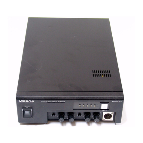
NIPROS PS270 User manual

PS270/570
Volume1.5,1steditionVer.3.1(serialnumber735322andUpper)
Operating Instructions
Beforeoperatingthesystem,pleasereadthismanual
thoroughlyandretainitforfuturereference.

WARNING
For the customers in the U.S.A.
This equipment has been tested and found
to comply with the limits for a Class A
digital device, pursuant to Part 15 of the
FCC Rules. These limits are designed to
provide reasonable protection against
harmful interference when the equipment is
operatedin a commercial environment.
This equipment generates, uses, and can
radiate radio frequency energy and, if not
installed and used in accordance with the
instruction manual, may cause harmful
interference to radio communications.
Operation of this equipment in a residential
area is likely to cause harmful interference
in which case the user will be required to
correct the interference at his own ex-
pense.
You are cautioned that any changes or
modifications not expressly approved in
this manual could void your authority to
operate this equipment.
All interface cables used to connect periph-
erals must be shielded in order to comply
with the limits for a digital device pursuant
to Subpart B of Part 15 of FCC Rules.
To reduce the risk of fire or electric
shock,do not expose this apparatus to rain
or moisture.
To avoid electrical shock, do not open the
cabinet. Refer servicing to qualified per-
sonnel only.
WARNING
When installing the unit, incorporate a
readily accessible disconnect device in the
fixed wiring, or connect the power plug to
an easily accessible socket-outlet near the
unit. If a fault should occur during opera-
tion of the unit, operate the disconnect
device to switch the power supply off, or
disconnect the power plug.
Do not install the appliance in a confined
space, such as book case or built-in cabi-
net.
IMPORTANT
The nameplate is located on the bottom.
WARNING
Excessive sound pressure from earphones
and headphones can cause hearing loss.In
order to use this product safely, avoid
prolonged listening at essive sound pres-
sure levels.This equipment shall not be
exposed to excessive heat such as sun-
shine, fire or the like.
NIPROS/1 is class 1 laser product.
(IEC60825-1+A2:2001)
Do not directly look into the Optical fiber
connector, since laser light is emitted from
its tips.
Ensure that the dust cap is placed over the
Optical fiber connector when this equip-
ment is not in use.
02

PS-270各部名称と働き
08
OpticalFiberCameraAdapterPS-270
コネクタパネル
Connectorpanel
OutputtheremotecontrolsignaltoaSONYcamcorderequippedwiththeLANCterminal(φ2.5mini-jack).
カメラのTCOUTから接続してPS-570に接続されたVTR等との同期を取るためのコネクタです。
カメラのTCINへ接続してPS-570に接続されたVTR等からのタイムコード信号により同期を取るためのコネクタです。
LANCconnector
TCINconnector
TCOUTconnector
Connectthetimecodesignalfromthecamcordertosynchronizewithvideoequipmentconnectedto
theOpticalFiberBaseStationPS-570.
OutputthetimecodesignaltothecamcorderfromtheOpticalFiberBaseStationPS-570tosynchronize
withvideoequipmentconnectedtotheOpticalFiberBaseStationPS-570.
ソニー社製LANCリモコンに対応するリモコン用φ2.5ジャックです。
GENLOCK信号を出力するコネクタです。
GENLOCKoutputconnector
ソニー社製RM-B150,750に適合するコネクタです。RCC-450(付属)を使ってカメラと接続します。
REMOTEconnector
OutputtheGenlockreferencesignaltothecamcorder.
Connectwiththeremotecontrolunit,SONYRM-B150,B750,andconnecttothecamcorderbythesupplied
8-pinremotecable.

PS-570各部名称と働き
NamesandFunctionsofParts
09
OpticalFiberBaseStationPS-570
前面パネル
Frontpanel
Turnsthepoweronoroff.
光信号の通信状況を表示します。
HD:HD-SDI信号がカメラアダプタから送られてきているとき点灯します。消灯の場合はSD-SDI信号が伝送されています。
LS:レーザー信号がカメラアダプタから送られてきているとき点灯します。
電源をON/OFFします。
POWERswitch
Operationstatusindicator
Showsthecurrentsystemstatus.
HD:LightsupwhentheHD-SDIsignalfromtheOpticalFiberCameraAdaptorPS-270isreceived.
LS:LightsupwhentheLasersignalfromtheOpticalFiberCameraAdaptorPS-270isreceived.
LEDOFF:WhentheSD-SDIsignalisreceived.
4W
I/O
EXTLINE(4WI/O) INTERCOM HEADSET
INTERCOMEXTLINE4WI/OON/OFFswitch
Turnsonorofftheconnectiontotheexternal4-wireintercomline.
外部インターカム4Wラインへの接続をON/OFFします。

05
OpticalFiberCameraAdapterPS-270
前面パネル
Frontpanel
PS-570から供給される12V系電源を出力するキャノン4Pメス出力です。カメラ、カムライト、LCDモニター等の電源に
使用します。
DC12VOUTconnector(XLR-4,female)
モニターにVF6Pケーブルを使って接続します。
LightsupwhenreceivingthetallysignalfromtheOpticalFiberBaseStationPS-570.
ThelightcanbeturnedonandoffwiththeTALLYON/OFFswitch.
MONITOROUTconnector
TALLYindicator
TALLYON/OFFswitch
タリーLEDをON/OFFするスイッチです。
TurnstheTALLYindicatoronandoff.
Connecttothemonitorbythesupplied6-pincable.
OutputsDC12VpowersuppliedfromtheOpticalFiberBaseStationPS-570foracameralight,amonitor,
aprompter,andetc.(themaximumelectricpoweris30W)
PS-570からのタリー信号を受けて点灯します。タリーON/OFFスイッチにより任意に消灯させることができます。

06
OpticalFiberCameraAdapterPS-270
背面パネル
Rearpanel
リアパネルのタリー表示を任意に点灯/消灯するためのスイッチです。
PS-570からタリー信号を受けて点灯します。タリー表示ON/OFFスイッチをOFFにすると消灯したままになります。
TALLYindicator
TALLYON/OFFswitch
TurnsonorofftheTALLYindicatorontherearpanel.
LightsupwhenreceivingthetallysignalfromtheOpticalFiberBaseStationPS-570.
ItdoesnʼtlightupwhentheTALLYON/OFFswitchisturnedoff.
ベースステーションPS-570と光ケーブル(別売ALC-100M等)にて接続するコネクタです。最大2kmまで使用可能です。
OpticalCableconnector
INTERCOMHEADSET2TALKSWITCHconnector
ConnectswiththeOpticalFiberBaseStationPS-570withanopticalfibercable.
Themaximumlengthofanopticalfibercableis2000m.
このコネクタをショートするとインカム2のマイクが動作します。
Whenthisconnectorisshorted,themicrophoneofintercomheadset2operates.
チップ
スリーブ
MICON
GND

07
OpticalFiberCameraAdapterPS-270
コネクタパネル
Connectorpanel
インカムを使用する場合にヘッドセット(DL-400)を挿入するコネクタです。
DC12V電源を入力することが可能です。
インカムを使用する場合にヘッドセット(DL-400)を挿入するコネクタです。
キャノン4Pオスコネクタのヘッドセットを使用する場合は、
キャノン4Pメス-メスのケーブルを製作して使用して下さい。
INTERCOMHEADSET2connector
HD-SDIまたはSD-SDI信号を入力するBNCコネクタです。
HD-SDI/SD-SDIinputconnector
RET映像(コンポジット)を出力するコネクタです。
REToutputconnector
1
2
3
4
DC12V(G)
DC8.4V(G)
DC8.4V(+)
DC12V(+)
1
2
3
4
MIC(G)
MIC(H)
H.PHONE(G)
H.PHONE(H)
DC12V/INTERCOMHEADSET1connector
ConnectthesuppliedIntercomheadsetDL-400.
OrconnecttheDC12VpowersupplyforDCoperation.
ConnectsthesuppliedIntercomheadsetDL-400.
ハンディカメラ用8.4V及びワイヤレス用12Vを出力するコネクタです。
DCOUTconnector
OutputDC8.4Vpowertothecamcorderand
DC12Vpowertoawirelessreceiverwiththe
suppliedDCcable.
ConnectortoinputtheHD-SDIorSD-SDIoutputsignalfromthecamcorder.
Outputsthereturnvideosignal.(Composite)
1
23
4
1
2
3
4
1
2
3
4
IncaseusingtheheadsetwiththeXLR-4PMaleconnector,
makeandusethecablewiththeXLR-4PFemale-Female
connectors.

08
OpticalFiberCameraAdapterPS-270
コネクタパネル
Connectorpanel
OutputtheremotecontrolsignaltoaSONYcamcorderequippedwiththeLANCterminal(φ2.5mini-jack).
カメラのTCOUTから接続してPS-570に接続されたVTR等との同期を取るためのコネクタです。
カメラのTCINへ接続してPS-570に接続されたVTR等からのタイムコード信号により同期を取るためのコネクタです。
LANCconnector
TCINconnector
TCOUTconnector
Connectthetimecodesignalfromthecamcordertosynchronizewithvideoequipmentconnectedto
theOpticalFiberBaseStationPS-570.
OutputthetimecodesignaltothecamcorderfromtheOpticalFiberBaseStationPS-570tosynchronize
withvideoequipmentconnectedtotheOpticalFiberBaseStationPS-570.
ソニー社製LANCリモコンに対応するリモコン用φ2.5ジャックです。
GENLOCK信号を出力するコネクタです。
GENLOCKoutputconnector
ソニー社製RM-B150,750に適合するコネクタです。RCC-450(付属)を使ってカメラと接続します。
REMOTEconnector
OutputtheGenlockreferencesignaltothecamcorder.
Connectwiththeremotecontrolunit,SONYRM-B150,B750,andconnecttothecamcorderbythesupplied
8-pinremotecable.

NamesandFunctionsofParts
09
OpticalFiberBaseStationPS-570
前面パネル
Frontpanel
Turnsthepoweronoroff.
光信号の通信状況を表示します。
HD:HD-SDI信号がカメラアダプタから送られてきているとき点灯します。消灯の場合はSD-SDI信号が伝送されています。
LS:レーザー信号がカメラアダプタから送られてきているとき点灯します。
電源をON/OFFします。
POWERswitch
Operationstatusindicator
Showsthecurrentsystemstatus.
HD:LightsupwhentheHD-SDIsignalfromtheOpticalFiberCameraAdaptorPS-270isreceived.
LS:LightsupwhentheLasersignalfromtheOpticalFiberCameraAdaptorPS-270isreceived.
LEDOFF:WhentheSD-SDIsignalisreceived.
4W
I/O
EXTLINE(4WI/O) INTERCOM HEADSET
INTERCOMEXTLINE4WI/OON/OFFswitch
Turnsonorofftheconnectiontotheexternal4-wireintercomline.
外部インターカム4Wラインへの接続をON/OFFします。

PS-270各部名称と働き
07
OpticalFiberCameraAdapterPS-270
コネクタパネル
Connectorpanel
インカムを使用する場合にヘッドセット(DL-400)を挿入するコネクタです。
DC12V電源を入力することが可能です。
インカムを使用する場合にヘッドセット(DL-400)を挿入するコネクタです。
キャノン4Pオスコネクタのヘッドセットを使用する場合は、
キャノン4Pメス-メスのケーブルを製作して使用して下さい。
INTERCOMHEADSET2connector
HD-SDIまたはSD-SDI信号を入力するBNCコネクタです。
HD-SDI/SD-SDIinputconnector
RET映像(コンポジット)を出力するコネクタです。
REToutputconnector
1
2
3
4
DC12V(G)
DC8.4V(G)
DC8.4V(+)
DC12V(+)
1
2
3
4
MIC(G)
MIC(H)
H.PHONE(G)
H.PHONE(H)
DC12V/INTERCOMHEADSET1connector
ConnectthesuppliedIntercomheadsetDL-400.
OrconnecttheDC12VpowersupplyforDCoperation.
ConnectsthesuppliedIntercomheadsetDL-400.
ハンディカメラ用8.4V及びワイヤレス用12Vを出力するコネクタです。
DCOUTconnector
OutputDC8.4Vpowertothecamcorderand
DC12Vpowertoawirelessreceiverwiththe
suppliedDCcable.
ConnectortoinputtheHD-SDIorSD-SDIoutputsignalfromthecamcorder.
Outputsthereturnvideosignal.(Composite)
1
23
4
1
2
3
4
1
2
3
4
IncaseusingtheheadsetwiththeXLR-4PMaleconnector,
makeandusethecablewiththeXLR-4PFemale-Female
connectors.

PS-270各部名称と働き
06
OpticalFiberCameraAdapterPS-270
背面パネル
Rearpanel
リアパネルのタリー表示を任意に点灯/消灯するためのスイッチです。
PS-570からタリー信号を受けて点灯します。タリー表示ON/OFFスイッチをOFFにすると消灯したままになります。
TALLYindicator
TALLYON/OFFswitch
TurnsonorofftheTALLYindicatorontherearpanel.
LightsupwhenreceivingthetallysignalfromtheOpticalFiberBaseStationPS-570.
ItdoesnʼtlightupwhentheTALLYON/OFFswitchisturnedoff.
ベースステーションPS-570と光ケーブル(別売ALC-100M等)にて接続するコネクタです。最大2kmまで使用可能です。
OpticalCableconnector
INTERCOMHEADSET2TALKSWITCHconnector
ConnectswiththeOpticalFiberBaseStationPS-570withanopticalfibercable.
Themaximumlengthofanopticalfibercableis2000m.
このコネクタをショートするとインカム2のマイクが動作します。
Whenthisconnectorisshorted,themicrophoneofintercomheadset2operates.
チップ
スリーブ
MICON
GND

PS-270各部名称と働き
05
OpticalFiberCameraAdapterPS-270
前面パネル
Frontpanel
PS-570から供給される12V系電源を出力するキャノン4Pメス出力です。カメラ、カムライト、LCDモニター等の電源に
使用します。
DC12VOUTconnector(XLR-4,female)
モニターにVF6Pケーブルを使って接続します。
LightsupwhenreceivingthetallysignalfromtheOpticalFiberBaseStationPS-570.
ThelightcanbeturnedonandoffwiththeTALLYON/OFFswitch.
MONITOROUTconnector
TALLYindicator
TALLYON/OFFswitch
タリーLEDをON/OFFするスイッチです。
TurnstheTALLYindicatoronandoff.
Connecttothemonitorbythesupplied6-pincable.
OutputsDC12VpowersuppliedfromtheOpticalFiberBaseStationPS-570foracameralight,amonitor,
aprompter,andetc.(themaximumelectricpoweris30W)
PS-570からのタリー信号を受けて点灯します。タリーON/OFFスイッチにより任意に消灯させることができます。

PS-270各部名称と働き
NamesandFunctionsofParts
04
OpticalFiberCameraAdapterPS-270
メインパネル
Mainpanel
コネクタパネルのヘッドセットコネクタ1(XLR-4P,キャノン4P)に接続されたヘッドセットDL-400のHPレベルおよび
SIDETONEレベルを調整するボリュームです。
INCOMHEADSET1H.PandSIDETONEvolumes
AdjuststheaudiolevelsofthemicrophoneandtheheadphoneoftheIntercomheadsetDL-400
connectedtotheHEADSET1connector(XLR-4P)ontherearpanel.
POWERswitch
電源をON/OFFするスイッチです。
Turnsthepoweronandoff.
電源スイッチがONになっている時に点灯します。
POWERindicator
Lightsupwhenthepowerswitchison.
PS-570からのタリー信号を受けて点灯します。
TALLYindicator
LightsupwhenreceivingthetallysignalfromtheOpticalFiberBaseStationPS-570.
AdjuststheaudiolevelsofthemicrophoneandtheheadphoneoftheIntercomHeadsetDL-400
connectedtotheHEADSET2connector(XLR-4P)ontherearpanel.
INCOMHEADSET2H.PandSIDETONEvolumes
コネクタパネルのヘッドセットコネクタ2(XLR-4P,キャノン4P)に接続されたヘッドセットDL-400のHPレベルおよび
SIDETONEレベルを調整するボリュームです。

NamesandFunctionsofParts
Mainpanel
Frontpanel
Rearpanel
Connectorpanel
Rearpanel
SystemConnection
Pre-adjustmentandSetting
SystemConnectionGuide
Multi-CameraSystemConnectionGuide
OutsideViewandDimensions
仕様
Specifications
Frontpanel
PS-270
LVM-89W/UniversulHead
4
5
PS-570
7
9
11
PS-270
LVM-89W 35
33
PS-570 34
PS-270
LVM-89W
37
38
PS-570
36
6
4
14
32
28
19
31
Tableofcontents
OpticalFiberStudioSystemNIPROS LS−270 & LS−570
03

15
LVM-89W
MENU/-/+buttons
MENU(select)button:selectsthemenufromthemenusdisplayed
onthescreeninsequenceasfollows.
-/+(entry)button:adjustseachsettingvalue.
WhentheResetmenuisselected,
eitherpressing-or+buttonresetsall
settingstothestandardvalue(50).
Reset(Pressingeither-or+buttonリセット
resetsallsettingsto“50”)
MENUメニューボタンを順次押して、スクリーンに表示されるメニューから設定項目を選択して、-/+ボタンで調節します。
Resetを選択して-/+ボタンいずれかを押すとすべての設定値が標準値(50)にリセットされます。
ThebrightnessoftheTALLYindicatorsonthefrontandrearpanelscanbeselectedbytheselect
switchesasfollows.
FRONTTALLYandREARTALLYdisplayselectswitch
フロントタリー、リアタリーの明るさの切替(OFF/L(low)/H(high))スイッチです。
H:Thetallyindicatorlightsupbrightly.
L:Thetallyindicatorisdimmedtothelowerbrightness.
OFF:Thetallyindicatoristurnedoff.
GREENTALLYindicatorontherearpanellightsupwhenthetallysignal(2〜4V=GREEN)isinput
totheTALLYINconnectorontheconnectorpanel.
ThebrightnessoftheindicatorcanbeselectedbytheREARTALLYdisplayselectswitch.
REARGREENTALLYindicator
グリーンタリーは、コネクタパネルのTALLYINコネクタに入力されるタリー信号(2〜4V=GREENON)により点灯します。
フロントパネルのリアタリー切替スイッチ(OFF/L(low)/H(high))で明るさの切替えが可能です。
REDTALLYindicatorontherearpanellightsupwhenthetallysignal(4〜V=RED)isinputtothe
TALLYINconnectorontheconnectorpanelorthetallysignal(0V=ON,OPEN=OFF)isinputtothe
MONIIFconnector.
ThebrightnessoftheindicatorcanbeselectedbytheREARTALLYselectswitch.
REARREDTALLYindicator
レッドタリーは、コネクタパネルのTALLYINコネクタに入力されるタリー信号(4V以上=REDON)により点灯します。
また、MONIIFコネクタに入力されるタリー信号(0V=ON)でも点灯します。
フロントパネルのリアタリー切替スイッチ(OFF/L(low)/H(high))で明るさの切替えが可能です。
LVM-89W各部名称と働き
HDMI/HDComponentMonitorLVM-89W/UniversalHead

16
LVM-89W
Fullcolor
BLUEONLY
GREENONLY
REDONLY
←←←←
RGBbutton:BypressingRGBbutton,selecttheimage,theblueonly,greenonly,orredonlyasfollows.
COLOR/MONObutton:BypressingCOLOR/MONObutton,selecttheimage,thecolorormonochrome.
INPUTselectbutton:SelecttheinputsignalconnectedtotheHD(Y/B-Y/R-Y)component,CMPIN
(compositesignalinput),andHDMIconnector.
BypressingINPUTbutton,selecttheinputmodeinsequence.Theselected
modeisdisplayedonthescreen.
Functionbuttons
PEAKINGbutton:BypressingPEAKINGbuttonselectthepeakingfunctionONorOFF.
WhenPEAKINGisON,thepeakinglevelisadjustablebytheMENUand-/+button.
16:9/4:3button:Bypressing16:9/4:3button,selecttheframesize16:9or4:3.
INPUT(入力セレクト)ボタンで、HDコンポーネントコネクタ、CMPINコンポジット入力コネクタ,HDMIコネクタに
接続された信号から入力する信号を選択します。INPUTボタンを順次押して、選択します。
選択された入力モードが画面に表示されます。
INPUTselectbutton
COMP1
COMP2
CVBS1
CVBS2
HDMI
←←←←←
HDcomponent:HD/Y,HD/B-Y,HD/R-Y
NC
composite:CMPIN(BNC)connector
HDMI:HDMIconnector
(BNC)connector
mode(insequence) signal:inputconnector
PEAKING(ピーキング)ボタンでON/OFFします。ONのとき、ピーキングレベルはメニューで調節できます。
16:9/4:3ボタンでフレームサイズの切替えができます。
RGBボタンでBLUEONLY,GREENONLY,REDONLYの切替えが可能です。
COLOR/MONOボタンでカラー,モノクロの切替えが可能です。
MARKERbutton:BypressingMarkerbuttonselectthemarkerinsequenceasfollows.
nomarker
16:9
16:9withcrossmarker
4:3
4:3withcrossmarker
allmarkers
←←←
← ←
←
MARKER(マーカー)ボタンを押して順次マーカーサイズを切り替えます。
COLOR INPUTRGBMARKER
MONO
16:9
4:3
PEAKING
HDMI/HDComponentMonitorLVM-89W/UniversalHead
LVM-89W各部名称と働き
NC

17
LVM-89W
InputHDcomponentsignals.Theinputsignalsaredisplayedwhentheinputselectmodeissettothe
“COMP1”mode.
HD/Y,HD/B-Y,HD/R-Yconnectors(BNC)
CMPINconnector(BNC)
Inputacompositevideosignal.Theinputsignalisdisplayedwhentheinputselectmodeissettothe
“CVBS1”mode.
CMPOUTconnector(BNC)
Outputsthecompositevideosignal.(ThroughoutputoftheCMPINinputsignal)
Inputthetallysignal(O〜2V=OFF,2〜4V=GREEN,4〜V=RED).
TALLYINconnector(BNC)
HDコンポーネント(HD/Y,HD/B-Y,HD/R-Y)信号を入力します。INPUT切替ボタンをCOMP1に切り替えて表示します。
コンポジットビデオ信号を入力します。INPUT切替ボタンをCVBS1に切り替えて表示します。
CMPINコネクタに入力されたコンポジットビデオ信号をスルーで出力します。
タリー信号を入力します。タリー信号の電圧により、2〜4VのときGREEN,4V以上のときREDが点灯します。
HDMI/HDComponentMonitorLVM-89W/UniversalHead
LVM-89W各部名称と働き
※カメラアダプターからのリターン信号(コンポジット)をモニターする場合は、リターン信号をこのコネクタに接続します。
Inordertomonitorthereturnvideosignal(composite)fromthecameraadaptor,connectthesignal
tothisconnectorwithBNCcable.
MONIIFconnector(6-pin,female)
TheDC12VpowerandthetallysignalaresuppliedfromtheCamera
Adaptorviathesupplied6-pincable(VC-450).
1
2
3
4
6
GND
+12VIN
SG
NC
TALLYIN5
約650mA
0V=ON
※専用6ピンケーブルのみ使用可能です。
Fortheuseofthesupplied6-pincableonly.
MONIIFconnector
(6-pin,female)
Pinassignment
カメラアダプタから付属の6ピンケーブルを通して、12V電源、タリー信号が入力されます。
NC
ConnectanexternalDC12Vpower.(10〜16V)
DC12VINconnector(XLR4-pin)
HDMIconnector
InputaHDMIsignalwithHDMIcable.Theinputsignalisdisplayedwhentheinputselectmodeisset
tothe“HDMI”mode.
1/4inchscrewhole
Fixthesupplieduniversalhead.
DC12V電源(10〜16V,ACアダプタ等)を接続します。
HDMIケーブルでHDMI信号を入力します。これは、INPUTボタンでHDMIに切り替えて表示します。
ユニバーサルヘッドを取り付けます。

18
UniversalHead
MonitorLockScrew(1/4inch)
AngleAdjustmentKnob
Slide-Shoe
1/4inchScrewHole
Slide-ShoeLockKnob
モニター固定ネジ
角度調節ノブ
スライドシュー固定ノブ
スライドシュー
1/4インチネジ穴
Usedtofixthemonitor.
Usedtoadjustthemonitorpositiontoanyanglesothatthedisplaycanbe
watchwell.
UsedtofixtheSlideShoetoacameraaccessoryshoe.
Slideintoacameraaccessoryshoe.
Usedtobefittedupwitha1/4inchcamerascrew(male).
Whenmountedonthecamerawiththe1/4inchscrewhole(female),install
supplied1/4inchmale-malescrewadaptprandfittedupwiththecamera.
HDMI/HDComponentMonitorLVM-89W/UniversalHead
LVM-89W各部名称と働き

SystemConnection
19
PMW-EX3の底面にPS-270をカメラネジでしっかり締めて固定します。
三脚に装着します。
FixthePS-270tightlytothebottomsurfaceofthecamcorderPMW-EX3withthecamerascrew(w1/4).
FixthecamcorderPMW-EX3toatripod.
モニター下部の1/4インチ固定ネジ穴にモニター固定ネジで固定します。
FixthesupplieduniversalheadtothescrewholeonthebottomsurfaceofthemonitorwiththeMonitor
LockScrew.
MakesurethePOWERswitchesofeachunitareoffbeforeconnection
1
2
3
PMW-EX3
Bottom
MonitorLockScrew
Universalhead
monitor
PS-270
OpticalFiberStudioSystemNIPROS PS−270 & PS−570
接続する前に、各機器の電源スイッチは必ずOFFにしてください。

20
PS-270とモニターLVM-89Wを6Pケーブル(VC-450)とBNCケーブルで接続します。
ConnecttheMONITOROUTconnectorofPS-270totheMONIIFconnectorofthemonitorwiththesupplied
6-pincable(VC-450)andconnecttheRETconnectortotheCMPINconnectorwithaBNCcable.
カメラのアクセサリーシューの止まる位置までスライドさせます。
シューから抜けないようにシュー固定ねじで固定します。
角度調整固定ねじを緩めてモニターの見やすい位置が決まった後、再度固定ねじを締めます。
SlidethemonitortothestoppositionoftheaccessoryshoeofPMW-EX3.
TightentheSlide-ShoeLockKnobtofixthemonitor.
LoosentheAngleAdjustmentKnoband
adjusttheangleofthemonitorsothatthemonitorcanbewatchedeasily,thentightentheknobagain.
monitor
PS-270
4
5
AngleAdjustmentKnob
Slide-ShoeLockKnob
Slide-Shoe
AccessoryShoe
MENU
-
+
FRONT TALLYREARTALLY
OFF L H OFF L H
REAKING 16:9 MARKER
RGB COLOR INPUT
4:3
MONO
HD/Y
HD/B-Y
HD/R-Y
CMPIN
CMPOUT
TALLYIN
MONIIF
DC12VIN
MONITOROUT
(6-pin)
MONIIF
NIPROS PS−570
SystemConnection
RET
(BNC)
LVM-89W
CMPIN
supplied6-pincable
(VC-450)
BNCcable
frontpanel
connector
Other manuals for PS270
1
This manual suits for next models
1
Other NIPROS Camera Accessories manuals
