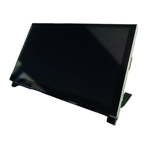
NIPROS HDM-70WV User manual

Operating Instructions
取扱説明書
Beforeoperatingthesystem,pleasereadthismanual
thoroughlyandremainitforfuturereference.
HDM-70WV/S
Volume1,1steditionVer.1.0
HDM-70WV
HDMonitor
HDモニター
ご使用の前に必ずこの取扱説明書をお読みください。
なお、取扱説明書は必要に応じてご覧になれるよう
大切に保管してください。

WARNING
For the customers in the U.S.A.
This equipment has been tested and found
to comply with the limits for a Class A
digital device, pursuant to Part 15 of the
FCC Rules. These limits are designed to
provide reasonable protection against
harmful interference when the equipment is
operated in a commercial environment.
This equipment generates, uses, and can
radiate radio frequency energy and, if not
installed and used in accordance with the
instruction manual, may cause harmful
interference to radio communications.
Operation of this equipment in a residential
area is likely to cause harmful interference
in which case the user will be required to
correct the interference at his own ex-
pense.
You are cautioned that any changes or
modifications not expressly approved in
this manual could void your authority to
operate this equipment.
All interface cables used to connect periph-
erals must be shielded in order to comply
with the limits for a digital device pursuant
to Subpart B of Part 15 of FCC Rules.
To reduce the risk of fire or electric
shock,do not expose this apparatus to rain
or moisture.
To avoid electrical shock, do not open the
cabinet. Refer servicing to qualified per-
sonnel only.
WARNING
When installing the unit, incorporate a
readily accessible disconnect device in the
fixed wiring, or connect the power plug to
an easily accessible socket-outlet near the
unit. If a fault should occur during opera-
tion of the unit, operate the disconnect
device to switch the power supply off, or
disconnect the power plug.
Do not install the appliance in a confined
space, such as book case or built-in cabi-
net.
IMPORTANT
The nameplate is located on the bottom.
WARNING
Excessive sound pressure from earphones
and headphones can cause hearing loss.In
order to use this product safely, avoid
prolonged listening at essive sound pres-
sure levels.This equipment shall not be
exposed to excessive heat such as sun-
shine, fire or the like.
02

各部名称と働き
NamesandFunctionsofParts
組み立て方法
Fixing
4
14
HDM-70WV目次
Contents目次
HDMonitorHDM-70WV
Frontpanel 4
Rearpanel 10
Leftside,Rightside,UpperandBottom 13
フロントパネル
リアパネル
左側面,右側面,上面,下面,
接続方法
Connection
調整・設定
AdjustmentsandSettings
付属品
Accessories 38
26
20
外形寸法図
OutsideViewandDimensions
仕様
Specifications
39
40
03

HDM-70WV各部名称と働き
NamesandFunctionsofParts各部名称と働き
04
フロントパネル
Frontpanel
Screen(withBezelandProtector)
FrontTALLYIndicatorLED(REDandGREEN)
LightsuptoREDorGREENwhenthetallysignalisinputtotheTALLYIN1connector.
OrlightsupwhentheonlyREDtallysignalisinputtotheTALLYIN2.
Thedisplayscreenis7.0inchesLCDwiththebezel(opensize:152.4mm91.4mm).
Andthescreeniscoveredwiththeprotector(181.4mm100.6mm).
スクリーンは7インチ液晶で、画面寸法は152.4mm92.4mmです。プロテクターで保護されています。
GREEN:LightsupwhenthesignaltotheTALLYIN1connectoris2-4V.
フロントタリーは、TALLYIN1のタリー信号でRED/GREENに点灯します。
または、TALLYIN2のタリー信号ではREDのみ点灯します。
GREEN:TALLYIN1コネクタの場合、タリー信号の電圧が2-4Vのとき
TALLYIN2コネクタの場合は、レッドのみ。タリー信号入力は、接点のshort/openです。
RED:LightsupwhenthesignaltotheTALLYIN1connectoris4-5V.
orwhenthesignaltotheTALLYIN2connectorisshortened.
RED:TALLYIN1コネクタの場合、タリー信号の電圧が4-5Vのとき
TCTALLY:ThefrontTALLYindicatorcanbeusedastheTCTALLYindicatorbytheMENUsetting.
(Seepage
TCTALLY(redonly)lightsupwhentheHD-SDIsignalwiththeembeddedTCsignal
isinputtotheSDI(HD/SD)INorRETINconnector.
TCTALLY:レッドタリーは、メニューでTCTALLYに設定できます。
TCTALLYは、TC信号をエンベデッドされたHD-SDI信号がSDI(HD/SD)IN1またはRETINに入力している
とき表示します。
HDMonitorHDM-70WV

NamesandFunctionsofParts
05
フロントパネル
Frontpanel
VOLUME/PUSHSELECTswitch
INPUTselectswitch
ZEBRAindicationon/offswitch
MARKERsizeselectswitch
Byrotatingtheknobadjusttheaudiovolumelevelofthemonitorspeaker(whentheheadphoneis
disconnected)ortheheadphonelevelconnectedtothejack().
Bypressingthisswitchselecttheaudiochannel,CH1&2→3&4→1→2→3→4→5→6→7→8→in
sequence,tomonitorbythemonitorspeakerortheheadphone.
SwitchestheZEBRAindication,onoroff.
TheleveladjustmentoftheZEBRAindication
isenableonthemenu.
SelectstheMARKERsizeinsequence.
ツマミを回して、背面のモニタースピーカーまたはヘッドホンでモニターする音量を調整します。
このツマミ(ボタン)を順次押すと、モニターする信号(モニタースピーカーまたはヘッドホンへ出力される信号)が切り替えられます。
(CH1&2→3&4→1→2→3→4→5→6→7→8→の順に切り替わります。)
INPUT切替スイッチを押して、入力映像信号を順に切り替えます。SDI(HD/SD)IN1[SDI-MAIN]→RETIN[SDI-RETURN]
→ANALOG(HD)component[COMPONENT]→I/F[CAMERA]の順に切り替わります。
入力をリターン信号(RETINコネクタ)にズームリモコンの操作で切り替えるとINPUT切替スイッチのLEDが点灯します。
ゼブラ表示をON/OFF切替えます。
ゼブラ出現レベルの調整は、メニューで設定できます。(ページ29参照)
[SDI-MAIN]SDIsignalinputtotheSDI(HD/SD)IN1connector
[SDI-RETURN]SDIsignalinputtotheRETINconnector
[COMPONENT]analog(HD)componentsignalsinputtotheANALOGY/PB/PRconnectors
Indication
onthescreen
RETURN
MAIN
LED
Inputsignal(inputconnector)
→OFF
↓
16:9
↓
16:9/+(centermarker)
↓
4:3
↓
4:3/+
↓
16:9/4:3
↓
16:9/4:3/+
↓
CROSSHATCH(LARGE)
↓
USERsetting
↓
POWERIndicator
LightsupwhenthePOWERswitchisturnedonandthepowerissuppliedtotheDCINconnector.
POWERスイッチがONのとき点灯します。
[CAMERA]VFsignalsinputtotheI/Fconnector(D-sub15-pin)fromthecamcorder.
マーカー表示を順に切り替えます。ユーザー設定(SAFETY、ユーザーマーカー)がメニューでできます。(ページ29参照)
CENTER[ON]
SAFTY[95%]
USERMARKER[OFF]
WIDTH
HEIGHT
HORIZONTALMOVE
VERTICALMOVE
Menusetting
ZEBRA[OFF]OFForON
YUPPERLIMIT[95.0%]-7.3---95.0-109.1
YLOWERLIMIT[0.0%]-7.3-0.0----109.1
Menusetting
ONorOFF
80to99%/OFF
ONorOFF
ROT(rotating)
HDMonitorHDM-70WV
Selectsainputsignalbypressinginsequence.TheLEDindicatorontheINPUTswitchlightsup,
whenthe(SDI)RETINsignalisselectedbyoperatingthezoomremotecontroller.
(analog(HD)componentsignals)

NamesandFunctionsofParts
06
フロントパネル
Frontpanel
MENUbutton/ENTERknob-button
MENUbutton:PressingtheMENUbuttondisplaystheMENUonthescreen.ThentheLEDlightson.
ThecursorreturnstothepreviouslistbypressingthisbuttonwhiletheLEDlightson.
ENTERknob-button:RotatingtheENTERknob-buttonselectsthemenu,submenuandsetting.
Pressingthisbuttonconfirmstheselecteditemandmovesthecursortothenextlist.
MENUメニューボタン:MENUボタンを押すと、メニューが画面に表示されます。ボタンのLEDが点灯します。
MENUボタンのLEDが点灯しているときボイタンを押すとカーソルがもどります。
ENTERツマミ(ボタン):ENTERツマミを回して、メニューの項目、設定項目、設定値を選択します。
カーソルの項目でツマミを押すと、その項目が確定し、カーソルが次にアクセスします。
UTILselectswitch
※Seethemenulist,page8-9.
※メニューの内容は、8-9ページを参照してください。
ユーティリティー(測定器機能)を順次切り替えます。
Selectstheutilityfunctioninsequenceasfollows.
ウェーブフォーム→
ウェーブフォーム+ベクトルスコープ→
ウェーブフォーム+オーディオ8CH→
ウェーブフォーム+ベクトルスコープ+オーディオ8CH→
ウェーブフォーム(全画面)→
ベクトルスコープ(全画面)→
ウェーブフォーム+ベクトルスコープ+オーディオ16CH→
マルチビュー(全機能表示)→
ユーザー設定→
OFF→
ユーザー設定で機能の選択等ができます。
(ページ30-33参照)
MENUbutton ENTERknob-button
LED
USERpresetfunctionsworkwhenvideosignalisinput.
注意:各機能は、信号が入力されているとき動作、操作ができます。
信号が入力されているとき操作,設定していた機能は、信号が遮断されると操作できなくなります。
MONOswitch
Selectstheimage,monochrome(LEDon)orcolor.
画面表示のカラー,モノクロの切替えをします。
RGBswitch
Selectstheimage
(Blueonly,GREENonly,REDonly,fullcolor)insequence. →Blueonly
↓
GREENonly
↓
REDonly
↓
fullcolor(LEDoff)
↓
→WAVEFORM
↓
WAVEFORM+VECTORSCOPE
↓
WAVEFORM+AUDIO8CH
↓
WAVEFORM+VECTORSCOPE+AUDIO8CH
↓
WAVEFORM(fullscreen)
↓
VECTORSCOPE(fullscreen)
↓
WAVEFORM+VECTORSCOPE+AUDIO16CH
↓
MultiView(allfunctions)
↓
USERsetting
↓
OFF(LEDoff)
↓
ブルーオンリー→グリーンオンリー→レッドオンリー→フルカラー→の順に切り替えます。
HDMonitorHDM-70WV

NamesandFunctionsofParts
07
フロントパネル
Frontpanel
BRIGHTlevelcontrolvolumeandselectswitch/LEDIndicator
CONTRASTcontrolvolumeandselectswitch/LEDIndicator
このツマミを押すとユーザー設定と標準設定(デフォルト)とが切替えできます。
ユーザー設定のときLED表示が点灯します。BRIGHT(明るさ)は、ツマミを回して調節します。
STANDARD(デフォルト標準値)は、BRIGHT=50に設定されています。
PressingtheknobselectstheUSERsettingorSTANDARD(default)setting.
WhenUSERsettingisselected(LEDindicatorlightson),rotatingthisknobadjuststhebrightness.
WhentheSTANDARDsettingisselected(LEDlightsoff),thebrightnessissettothefactorysetting(50).
このツマミを押すとユーザー設定と標準設定(デフォルト)とが切替えできます。
ユーザー設定のときLED表示が点灯します。コントラストは、ツマミを回して調節します。
STANDARD(デフォルト標準値)は、コントラスト=80に設定されています。
USERpresetfunctions,etc.canoperatewhenvideosignalisinput.
注意:各機能は、信号が入力されているとき操作ができます。
信号が入力されているとき操作,設定されていた機能は、入力が遮断されると操作できなくなります。
(2)Rotatingknobadjusts(confirms)avalue.
(1)PressingknobselectsUSERsettingandLEDlightson.
LED
LED LED
PressingtheknobselectstheUSERsettingorSTANDARD(default)setting.
WhenUSERsettingisselected(LEDindicatorlightson)rotatingthisknobadjuststhecontrast.
WhentheSTANDARDsettingisselected(LEDlightsoff),thecontrastissettothefactorysetting(80).
SHARPNESS
SHARPNESScontrolvolumeandselectswitch/LEDIndicator
このツマミを押すとユーザー設定と標準設定(デフォルト)とが切替えできます。
ユーザー設定のときLED表示が点灯します。シャープネスは、ツマミを回して調節します。
STANDARD(デフォルト標準値)は、シャープネス=50に設定されています。
PressingtheknobselectstheUSERsettingorSTANDARD(default)setting.
WhenUSERsettingisselected(LEDindicatorlightson)rotatingthisknobadjuststhesharpness.
WhentheSTANDARDsettingisselected(LEDlightsoff),thesharpnessissettothefactorysetting(50).
PICTURE
ピクチャー
RETURN
SATURATION[50]
SHARPNESS[50] 0/---/50/---/100
0/---/50/---/100
Thesharpnessadjustmentisenableonthemenu,too.
シャープネスはメニューでも設定できます。
HDMonitorHDM-70WV

NamesandFunctionsofParts
08
OperatingtheMenusメニューの操作
Press
Rotate
MenuDisplay メニューの表示
PresstheMENUbutton.
Themenulistisdisplayedonthescreen.
VECTORSCOPE[ON]
ZEBRA[OFF]
SETUP
WAVEFORM[ON]
INFO[1080i/60]
MARKER
AUDIO[ON]
INPUTSDI-MAIN
VERSION###
VIDEOFORMAT1080i/60
Press
PICTURE
MenuSetting
MenuSelectionandfixing
SubmenuSelectionandfixing
Settingandfixing
ByrotatingtheENTERknobbutton
movethecursortothedesireditem
positionandthenthesubmenulist
isdisplayed.
Presstheknobtofixtheselected
itemandthecursormovestothe
submenulist.
VECTORSCOPE[ON]
ZEBRA[OFF]
SETUP
WAVEFORM[ON]
INFO[1080i/60]
MARKER
AUDIO[ON]
PICTURE
Menulist
Menulist
ByrotatingtheENTERknobbutton
movethecursortothedesireditem
position.
Presstheknobtofixtheselected
itemandthesettinglistisdisplayed
andthecursormovestothesetting
list.
Submenulist
ByrotatingtheENTERknobbutton
movethecursortothedesiredsetting
position(value).
Thenpresstheknobtofixtheselected
item.
Thecursorreturnstothesubmenulist.
Submenulist
Settinglist
Settinglist
Submenulist
メニューの設定
Press
Rotate
Press
Rotate
RETURN
WAVEFORM[ON]
DISPTYPE[OVERLAY]
YOVERLIMIT[95.0%]
YUNDERLIMIT[0.0%]
RETURN
WAVEFORM[ON]
DISPTYPE[OVERLAY]
YOVERLIMIT[95.0%]
YUNDERLIMIT[0.0%]
RETURN
WAVEFORM[ON]
DISPTYPE[OVERLAP]
YOVERLIMIT[95.0%]
YUNDERLIMIT[0.0%]
Rotate
Rotate
Press
Press
Rotate Press
HDMonitorHDM-70WV

NamesandFunctionsofParts
09
VECTORSCOPE[ON]
ZEBRA[OFF]
SETUP RETURN
TIMECODEDISP[OFF]
TIMECODETYPE[LTC]
TCTALLY
[OFF]
LOWTALLYBRIGHT[3]
BACKLIGHT
[100%]
PICTUREDELAY[NORMAL]
ANALOGCALIBRATE
>
RESETTODEFAULT>
WAVEFORM[ON]
<MENU>メニュー <Submenu&[factorysetting]>設定項目 <Setting>設定値
RETURN
WAVEFORM
[ON]
DISPTYPE[OVERLAY]
YOVERLIMIT
[95.0%]
YUNDERLIMIT[0.0%]
RETURN
VECTORSCOPE
[ON]
DISPTYPE[OVERLAY]
GAIN
[1.00]
RETURN
ZEBRA
[OFF]
YUPPERLIMIT[95.0%]
YLOWERLIMIT[0.0%]
ON/OFF
OFF
IN1
IN1/RET
LTC
VITC1
VITC2
AUDIO[ON] RETURN
LEVELMETER[ON]
DISPLAYCHANNELS[8]
DISPTYPE
[OVERLAP]
HEADROOMSTART-20dB]
HEADROOMEND[-6dB]
FRONTVOLUME[15]
FRONTLEFTCH[1CH]
FRONTRIGHTCH[2CH]
REARLEFTCH[1CH]
REARRIGHTCH[2CH]
オーディオ
ウェーブフォーム
ベクトルスコープ
ゼブラ
セットアップ
PICTURE
ピクチャー
RETURN
SATURATION[50]
SHARPNESS
[0] 0/---/50/---/100
0/---/50/---/100
MARKER
マーカー
RETURN
CENTER[ON]
SAFTY
[95%]
USERMARKER[OFF]
WIDTH
HEIGHT
HORIZONTALMOVE
VERTICALMOVE
CANCEL/8COLORCALNOW
OFF/ON
ON/OFF
1/2/3/4/5/6/7/8
OVERLAP/OVERLAY
-60dB/---------
---------/-0dB
0/------------/40
1/------/8
1/------/8
1/------/8
1/------/8
CANCEL/CONFIRM
MENUlistメニュー項目
-7.3/--------/109.1
-7.3/--------/109.1
1.00/1.02/----/4.98
OVERLAY/OVERLAP
ON/OFF
ON/OFF
80%/---/95%/--/99%/OFF
ON/OFF
ROT
ON/OFF
OVERLAY/OVERLAP
-7.3/---------/109.1
INPUTSDI-MAIN
VIDEOFORMAT1080i/60
VERSION###
INFO[1080i/60]
ROT
ROT
ROT
HDMonitorHDM-70WV
1/-/3/-------/8
2/---------/100
-7.3/---------/109.1
CANCEL/RESETNOW
CANCEL/CONFIRM
NORMAL
FAST
FASTEST
COLORMATRIX
[YPBPR]
REDBIAS[0]
GREENBIAS[0]
BLUEBIAS[0]
REDGAIN[1.00]
GREENGAIN[1.00]
BLUEGAIN[1.00]
COLOR
カラー
0.500/-----1.992
-128/-----/127
YPBPR
RGB
0.500/-----1.992
0.500/-----1.992
-128/-----/127
-128/-----/127

NamesandFunctionsofParts
10
リアパネル
Rearpanel
RearTALLYIndicator(REDonly)
LightsuptoREDwhenthetallysignalisinputtotheTALLYIN1orTALLYIN2.
ThebrightnessisexchangeabletoOFF/L(low)/H(high)bytheTALLYOFF/L/Hdisplayselectswitch.
リアタリー(レッドのみ)は、TALLYIN1またはTALLYIN2のタリー信号で点灯します。
リアタリー(レッドのみ)は、切替スイッチでOFF(消灯)/L(low減光)/H(high)に切り替えることができます。
TCTALLY:ThefrontTALLYindicatorcanbeusedastheTCTALLYindicatorbytheMENUsetting.
(Seepage
TCTALLY(redonly)lightsupwhentheHD-SDIsignalwiththeembeddedTCsignal
isinputtotheSDI(HD/SD)INorRETINconnectors.
TCTALLY:レッドタリーは、メニューでTCTALLYに設定できます。
TCTALLYは、TC信号をエンベデッドされたHD-SDI信号がSDI(HD/SD)IN1またはRETINに入力している
とき表示します。
HDMonitorHDM-70WV
I/Fconnector(HDD-sub15-pin,female)
UsedforconnectingtheHDM-70WV
insteadoftheVFtotheVFconnector
ofthecamera.
ConnecttheHDD-sub15-pincable
fromtheVFconnectorofthecamera.
VFの代わりにHDM-70WVを接続する場合に
使用します。
カメラのVFコネクタからD-sub15ピンケーブル
(別売オプション)で接続します。
NOTE:UsethededicatedcableonlytoconnecttheHDM-70WVtothecamcorder.
Failingtodosomaycauseamalfunctionordamagetothecamcorder.
注意:VFコネクタとの接続には、専用のケーブルをご使用ください。そうしないと、カムコーダーが故障、破損するおそれがあります。
1
6
11
1R-YIN
2YIN
3B-YIN
4RECTALLY
5SHIELD
6AGNDR-Y
7AGNDY
8AGNDB-Y
9BATIND
10PGND
11SLD
12SDA
13POW(+12V)
14POW(+12V)
15SCL
HDD-sub15-pinConnector
PinAssignment

NamesandFunctionsofParts
11
リアパネル
Rearpanel
SDI(HD/SD)IN1connector(BNC)
SDI(HD/SD)RETIN(SDIreturnsignalinput)connector(BNC)
SDI(HD/SD)1OUTconnector(BNC)
ANALOGY/PB/PRconnectors(BNC)
RETIN(returncontrolsignalinput)connector(8-pin)
InputtheHD-SDIorSD-SDIsignalfromacamera,etc.
OutputstheHD-SDIorSD-SDIsignalinputtotheSDI(HD/SD)IN1connector.
Connecttotheinputofaswitcher,etc.
Inputthereturnvideosignal(HD-SDIorSD-SDI)fromaswitcher,etc.
InputtheANALOGHDY/PB/PRcomponentsignalsfromacamera,etc.
Connecttotheoutputofazoomremotecontrollerwiththe8-pincableoftheremotecontroller.
Ifnecessaryconnectthesuppliedzoomremotecontrollerextentioncable(0.3m).
Usedforswitchingtheinputsignal,fromtheSDIINsignaltotheRETINsignal.
HD-SDIまたはSD-SDI信号をカムコーダー等から入力します。
SD(HD/SD)IN1コネクタに入力されたHD-SDI/SD-SDI信号をスルーで出力します。
スイッチャー等の入力へ接続します。
リターンビデオ信号(SDI(HD/SD))を入力します。スイッチャー等の出力から接続します。
アナログHDY/PB/PRコンポーネント信号をカムコーダー等から入力します。
ズームリモコン(別売オプション,AS-520)を接続します。必要ならば、付属の延長ケーブルを接続します。
ズームリモコンでリターン切替に使用します。
TALLYOFF/L/Hdisplayselectswitch
Thebrightnessofthereartallyindicator(REDonly)canbeselectedasfollows.
H:Thetallyindicatorlightsupbrightly.
L:Thetallyindicatorisdimmedtothelowerbrightness.
OFF:Thetallylampispreventedfromlighting.
リアタリー(レッドのみ)を(OFF(消灯)/L(low:減光)/H(high))に切替えます。
HDMonitorHDM-70WV
TALLY2connector(BNC)
Whenthisconnectorisshortened,boththefrontandreartallyindicatorslightuptoRED.
TALLY2コネクタは、入力をショートするとレッドタリーが点灯します。
TALLY1connector(BNC)
Inputatallysignaltolightupthefrontandthereartallyindicators.
ThefronttallyindicatorlightsuptoREDorGREENaccordingtothevoltageofthetallysignal.
(RED:4-5V,GREEN:2-4V).
ThereartallyindicatorlightsuponlytoRED.
タリー信号を入力します。
フロントタリーは、タリー信号の電圧によってRED(4〜5V)またはGREEN(2〜4V)に点灯します。
リアタリーはレッドのみです。

NamesandFunctionsofParts
12
リアパネル
Rearpanel
Fan
WorkswhenthePOWERswitchisturnedon.
電源スイッチをONすると、ファンが回転します。
DCINconnector(XLR4-pin)
POWERswitch
ConnecttothesuppliedACAdaptortosupplyDC12Vpower.
TurnsonthepowersupplythroughtheDCINconnector.
Whenthepowerissupplied,thePOWERindicatoronthefrontpanellightson.
ACアダプタを接続して電源を供給します。
電源スイッチをONすると、前面パネルの電源表示LEDが点灯します。
Monitorspeaker
UsedtomonitortheaudiosignalselectedbypressingtheVOLUME/PUSHSELECTswitch.
Whenaheadphoneisconnectedtothejack,themonitorspeakerdoesnʼtwork.
VOLUME/PUSHSELECT(ボリューム/切替)スイッチを押して選択した音声信号をモニターします。
ヘッドホンが差し込まれていると、モニタースピーカーからは音はでません。
BaseStand(Locationstand)
Thedisplayangleofthescreencanbechanged(angleofelevation=20).
スタンドは、画面の角度を変えることができます。(仰角20)
AUDIOOUT1/2(XLR3-pin2)
Outputsthede-embeddedanalogaudiosignalsfromtheHD/SD-SDIinputsignaltotheSDIINI
connector.TheoutputaudiochannelfromCH1toCH8canbeselectedbytheAUDIOmenusetting.
(SeeAudiosignaloutputselect,page35)
Theoutputaudiosignalcanbemonitoredwiththemonitorspeakeroraheadphone.
オーディオ信号を出力します。SDIIN1コネクタに入力したHD-SDI信号のエンベデッドオーディオ信号が出力されます。
CH18から出力する信号をメニューの設定で選択できます。
出力する信号は、モニタースピーカーまたはヘッドホンでモニターできます。
V-shoemountwithDCINconnector
ConnecttheLi-ionbatterypacktosupplytheDCpower.
リチウムイオンバッテリーパックを装着します。
HDMonitorHDM-70WV
RETOUT(returncontrolsignaloutput)connector(8-pin)
Connecttothezoomlensofacamcorderwiththesupplied8-pinzoomlensremotecontrolcable(1m).
Usedforthelenszoomingandtherecordingstart/stopoftheVTR.
ズームリモコン用リモートケーブル(付属)を接続してカムコーダー(レンズ)へリモート信号(リターン切替、ズーミング、VTR録画/停止)
を出力します。

NamesandFunctionsofParts
13
左側面.右側面および上面,底面
Leftside,Rightside,Upper&Bottom
Screwholes(2-w1/4(left,right))
Usedtofixthesuppliedtiltarmstay.
アームステー(付属)を取り付けます。
Camerascrewholes(2-w1/4(top,bottom)andw
3/8(bottom))
Usedtobefittedtoatripodortothesupplieduniversalhead.
三脚等またはユバーサルヘッドへの取り付けに使用します。
Headphonejack(φ6.3stereojack)
ConnectaheadphonetomonitortheaudiosignalselectedbypressingtheVOLUME/PUSHSELECT
switch.
ヘッドホンを接続してオーディオ出力をモニターします。VOLUME/PUSHSELECT(ボリューム/切替)スイッチを押して選択した
音声信号をモニターします。
Upper Bottom
Rightside
Leftside
Handle
Usedforcarrying.
持ち運び用取っ手。
HDMonitorHDM-70WV

HDM-70WV組み立て方法
Fixing組み立て方法
14
アームの取り付け方法
VFTiltArmStayFixing
Makesuretodisconnecttheconnectorsbeforefixingup.
1
PreparethesuppliedVFTiltArmStay,fivearmstayscrewsandwashers(oneisusedtofixuptoacamera),
andtwocombinationwashers,.
アームとw1/4アームステーネジ5本(うち1本はカメラ等への固定用)、ワッシャー、ゆるみ防止コンビネーションワッシャー2個
を用意します。
TightenthearmstayscrewstothescrewholesontheleftandrightsideoftheMonitorusingrubber
washersandcombinationwashersasshownintheFig.
2
本体左右の側面のネジ穴にラバーワッシャーとコンビワッシャーとを使ってアームステーネジを図のように締め付けます。
組み立ては、必ず入出力コネクタの配線をはずしてから行ってください。
nylon
washer
rubberwasher rubberwasher
combinationwasher
コンビネションワッシャー
VFTiltArmStay
VFチルトアームステー
w1/4
armstayscrew
w1/4armstayscrew
gaptoinsertthearmstay
隙間にアームステーを挿入します
rubberwasher
combinationwasher
gap
HDMonitorHDM-70WV

15
Fixing
アームの取り付け方法
3
InserttheVFArmStayintothegapbetweenthecombinationwasherandthescrew,andtightenthearm
stayscrewwiththerubberwasher.
アームをコンビネーションワッシャーのすきまに挿入し、アームステーネジをゴムワッシャーを使って固定します。
Tofixonacamcorderortothesuppliedswingarmtightenthew1/4armstayscrewwithnylonwasher
onthebottomofthearmstay.
4
アームステー底面のw1/4アームステーネジで、カメラ等へ取り付けます。
VFTiltArmStayFixing
w1/4armstayscrew
rubberwasher
gaptoinserttheVFArmstay
w1/4
armstayscrew
VFArmstay
POWER INPUT ZEBRA
VOLUME
VFarmstay
swingarm
HDMonitorHDM-70WV

16
Fixing
スイングアームへの取り付け方法
MountingonSwingArm(forHDM-70WV/Sonly)
Makesuretodisconnecttheconnectorsbeforefixingup.
1
2
組み立ては、必ず入出力コネクタの配線をはずしてから行ってください。
CameraPlateカメラプレート
(bottmside)下面
TripodBase
三脚ベース
SwingArm
スイングアーム
(Screwsareattached
tothetripod)
Prepareatripodandremovethetripodbaseandthecameraplate.
三脚を用意し、三脚ベース、カメラプレートを外します。
TripodBase三脚ベース
CameraPlateカメラプレート
SwingArm
(supplied)
スイングアーム
partformountigHDM-70WV
HDM-70WV取付部
TripodBaseScrews(supplied)三脚ベースネジ
or
FixupthetripodbaseandthecameraplatetotheSwingArm.
スイングアーム本体(三脚取付部)の上面に三脚ベースを取り付け、下面に三脚のカメラプレートを取り付けます。
TripodBase三脚ベース
partforfittinguptotripod
(bottomside)三脚取付部(下面)
(arm)
partformountigHDM-70WV
HDM-70WV取付部
TripodBaseScrews
(supplied)
三脚ベース取付ネジ
HDMonitorHDM-70WV/S

17
Fixing
スイングアームへの取り付け方法
Mountacamcorderonthetripodbaseontheswingarm.
4
スイングアーム上の三脚ベースへカメラを取り付けます。
MountingonSwingArm(forHDM-70WV/Sonly)
3
FixuptheArmonthetripodandmountHDM-70WVonit.
アームを三脚に固定し、HDM-70WVをマウントします。
3-1
Incaseofusingarmstayfixwithw1/4
armstayscrew.
w1/4universalheadscrew
(supplied)
3-2
Incaseofusinguniversalhead(supplied),
fixwithw1/4universalheadscrew(supplied).
universalhead(supplied)
ユニバーサルヘッド
NOTE:MakesuretomountHDM-70WV
foldingtheSwingArmasshown
inFig.
注意:HDM-70WVをマウントする場合は、図のように、
必ずスイングアームを折りたたんだ状態で
行ってください。
アームステーを使用する場合は、w1/4アーム
ステーネジで固定します。
ユニバーサルヘッドを使用する場合は、w1/4
ユニバーサルヘッドネジで固定します。
STANDARD
ENTER USER
CONTRAST
BRIGHT
MENU
UTIL
MONO
RGB
MARKER
ZEBRA
INPUT
RETURN
MAIN
POWER
VOLUME
PUSHSELECT
w1/4
armstayscrew
VFtiltarmstay
Tripodbase
Swingarm
STANDARD
ENTER USER
CONTRAST
BRIGHT
MENU
UTIL
MONO
RGB
MARKER
ZEBRA
INPUT
RETURN
MAIN
POWER
VOLUME
PUSHSELECT
SHARPNESS
SHARPNESS
HDMonitorHDM-70WV/S

18
ロケ用スタンドの脱着方法
LocationStandRemovalandFixing
1Loosen/tightenfourscrewsonthebottomtoremove/fix.
本体の底面の4本のネジで行います。
Fixing
LocationStand(supplied)
ロケ用スタンド
PROTECH
LocationStand
HDMonitorHDM-70WV

19
Fixing
フードの取り付け方法
HoodMounting(forHDM-70WV/Sonly)
HDMonitorHDM-70WV/S
1
PreparethesuppliedHoodandfourscrews.
フードと固定ネジ4本を用意します。
Tightenfourscrewsontheleftandrightside.
2
本体の左右側面にフードを4本のネジで締め付けます。
HeadphoneJack
Hood

HDM-70WV接続方法
Connection接続方法
20
電源の接続方法
PowerSupplyConnection
MakesuretoturnoffthePOWERswitchofeachunitbeforeconnecting.
接続する前には、必ず各機器の電源スイッチをOFFにしてください。
1
ConnectthesuppliedACadaptortotheDCIN12Vconnector(XLR4-pin)ontherearpanel.
リアパネルのDCIN12Vキャノン4ピンコネクタにACアダプタを接続します。
WhenthePOWERswitchisturnedonand
thepowerissupplied,thePOWERIndicator
(LED)onthefrontpanellightsup.
2
電源が供給されると前面パネルの電源表示LEDが点灯
します。
POWERindicatorLED
POWERswitch
DCIN(12V)connector
ACAdaptor(supplied)
ACアダプター
XLR4-pin
NOTE:
WhenthepowerissuppliedfromaLi-ionbatterypack,connecttheLi-ionbatterypacktotheV-shoe
DCoutputconnector.
電源をリチウムバッテリーから供給する場合は、Vシューへ装着します。
PowerTapcable
(supplied)
カムタップ電源供給ケーブル fromCamcorder
カムコーダー
Lithiumionbatterypack
リチウムバッテリーパック
LITHIUMIONBATTERYPACK
or
HDMonitorHDM-70WV
This manual suits for next models
1
Table of contents
Other NIPROS Monitor manuals
