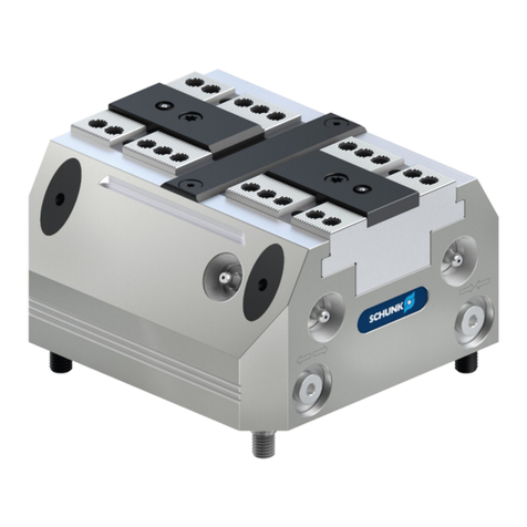
Nissei GTR-AR User manual

<Read this manual before using the product.>
NISSEI CORPORATION
Battery powered driver SD type
Instruction Manual

・Be sure to carefull
y
read the contents described in this instruction manual and
to understand how to use
p
roduct correctl
y
before usin
g
it.
・The extent of hazard/damage expected to occur in the case of improper handling
are classified and indicated in ranks of “DANGER”, ”WARNING”, and ”CAUTION.”
The definitions and indications are as follows.
■
D
escr
i
pt
i
on o
f
t
h
e sym
b
o
l
■
Th
e types o
f
contents to
b
e o
b
serve
d
are exp
l
a
i
ne
d
w
i
t
h
c
l
ass
ifi
cat
i
on
b
y grap
hi
ca
l
sym
b
o
l
s
b
e
l
ow.
Indicates "Fire Hazard." Indicates "Ground Connection."
If the product is used in an application such as a personnel transport device, make sure to install a
protective device for safety purposes. Failure to implement safety measures may result in personal
injury, death, and/or damage to the application.
If the product is used in an elevator, install a safety device on the application to prevent it from
falling. Failure to implement safety measures may result in personal injury, death, and/or damage to
the application due to the falling of the elevator.
Do not use the product under the explosive atmosphere. Failure to follow this precaution may result
in explosions, ignition of fire, fire, electric shock, injury, and/or damage to the application.
Danger
Cases where it is expected that a degree of danger is extremely high such that improper
handling possibly causes a dangerous situation to occur, which may lead to death or
serious injury.
Indicates
"What You Must Pay Attention To." Indicates "What You Must Not Do."
Introduction
Thank you very much for purchasing our product.
Safety Precautions
Even items described in “CAUTION” may lead to a serious results depending on the situation.
Be sure to observe every instruction which deals with important contents.
Indicates "Burn Hazard." Indicates "Do Not Disassemble."
Warning
Cases where improper handling possibly causes a dangerous situation to occur, which
may lead to death or serious injury.
Caution
Cases where improper handling possibly causes a dangerous situation to occur, from
which a minor or medium degree of injury may be incurred.
Indicates "Electric Shock Hazard." Indicates "What You Must Do."
Danger
■General
■Wiring
Do not change the wiring while the product is energized. Failure to follow this precaution may result
in fire, electric shock, and/or damage to the application.
Install a fuse and a circuit breaker on the power supply side to immediately stop the operations and
cut off the power supply in the event of current overflow.Negligence may cause accidents leading to
fire, electric shock, damage to the device, and/or other accidents.

Make sure the temperature of driver surface should not exceed 80℃.Failure to follow this
precaution may result in damage of the product and/or burn injury.
Caution
■General
Never perform operations with wet hands. Failure to follow this precaution may result in electric
shock.
Use the specified combination of the motor and driver. Negligence may cause fire and damage to
the equipment.
■Operation
Be sure not to approach to the application after a power failure.
Otherwise, sudden power recovery may cause injury.
Correctly connect the positive and negative sides of input voltage to this driver. Negligence may
cause failure/damage to the driver or accidents.
When the operation has stopped due to the occurrence of error or activated safeguards, do not re-
start the operation until the causes of error are determined and countermeasures are taken. Failure
to follow this precaution may result in damage to the application, injury, fire, electric shock, and/or
burns.
Warning
■General
The operators in charge of installation, piping, wiring, operation, handling, maintenance, and
inspection should have enough knowledge and technical skill related to the product. Failure to
follow this precaution may result in fire, electric shock, injury, and/or damage to the application.
This driver is not equipped with the function to prevent inrush current when power is supplied.
When power is supplied repeatedly at a frequency of once/hour or more or when inrush current
becomes a problem for the instrument, the customer is requested to take appropriate treatment.
Negligence may cause malfunction of/damage to the driver or accidents.
■Wiring
When changing the setting of the built-in trimmer, use a slotted screwdriver made of resin.
Negligence may cause electric shock or burns.
Input voltage to this driver must be within the allowable range. Using the driver with voltage outside
this range may cause failure/damage to the driver or accidents.
Regenerative energy is supplied to the power supply unit through this driver. When using a load
that generates regenerative energy, the customer is required to take measures appropriate for the
power supply unit. Negligence may cause malfunction of/damage to the driver or accidents.
Do not cut connection with the battery when the motor is regenerative running buring motions of
lowering and reducing speed and the main power supply(+) and controlled power supply(⊕) are
connected.
Failure to follow this precation may cause failure/damage to the driver and accidents.
Do not repair, disassemble or remodel the product. Failure to observe this precaution may result in
injury, fire, electric shock, and/or burns.
■Installation
Do not operate the product where it is exposed to water, corrosive atmosphere, flammable gas
atmosphere, and near the combustible material. Failure to follow this precaution may result in fire
and/or accident.
Do not remove the nameplate.
Operate the product under the conditions specified in this instruction manual. Failure to follow this
precaution may result in damage to the application and/or injury.
Do not expose the product to strong impacts/shocks. Failure to observe this precaution may result
in failure of the product and/or injury.

The contents of this manual are subject to change without notice.
We have made every possible effort to make the contents of this manual easy to understand. If there is anything that
is unclear or hard to understand, please feel free to contact us.
Do not touch the rotating part of the gearmotor. Failure to follow this precaution may result in injury.
Important
When disposing of the product, dispose of it as a general industrial waste. Please follow local laws and regulations if
any apply and take care of the waste accordingly.
Notice
We shall assume no responsibility or liability for any troubles caused by use that violates the cautions above.
Ensure that the wires to the power supply, motor, and driver are connected properly and securely.
Negligence may cause malfunction of the equipment, resulting in injuries.
■Operation
Immediately stop the operation if there is any abnormality. Failure to follow this precaution may
result in electric shock, injury, and/or fire.
Do not touch the gearmotor when the power is on or immediately after turning off the power, as
their surfaces may be hot for a while. Failure to follow this precaution may cause burns.
■Wiring
Be careful not to cause damage to the cable nor pull it strongly. Failure to follow this precaution
may result in injury, fire, and/or electric shock.
Do not put any combustible material near the product. Failure to follow this precaution may result in
fire.
Do not put any object that may prevent air from being circulated around the product. Failure to
follow this precaution may cause burns due to abnormal overheating, and/or fire.
Do not allow any foreign materials to enter the driver. Negligence may cause burns, fire and/or
electric shock.
Do not stand on or place any heavy object on the product. Failure to follow this precaution may
result in injury.
■Installation
Caution

Introduction
Safety precautions
1. Part number and Model Configuration P.6
2. Section Names P.7
3. External Dimensions P.10
4. Installation P.11
5. Wiring Diagrams P.12
6. External I/F Specifications P.16
7. I/O Terminal Wiring
7-1 Control input P.18
7-2 Control output P.19
7-3 External analog input P.19
8. User Constants
8-1 Setteing of Constants P.20
8-2 Constant list P.20
8-3 Constants explained P.25
9. Safeguards
9-1 Driver error list and display method P.40
9-2 Causes and countermeasures when safeguards P.41
are activated
9-3 Troubleshooting P.42
10. Specifications P.43
11. Accessories P.44
12. Conformity to Safety Standards (CE, KC) P.45
13. Storage, Warranty P.46
Contact Us P.47
Related Instruction Manual and Software P.48
Table of contents

■Driver model
The contents of Driver Model's codes are as follows.
Make sure the Driver Model on nameplate is consistent with your order.
■Model confi
g
uration
[1]
[2]
[4]
Motor power
80
[2]
Motor Ver
SD
[3]
Motor
classification
NB
A
SD
[1]
Series
A
[6]
Auxiliary code
X
[5]
Voltage
L4
ー
ー
Motor classification
Motor power
Voltage
Series
Motor Ver
Empty
080
L4
Motor power Voltage
0.75kW
DC48V
Driver model
0.75kW DC48V A-SDNB080L4
1. Part number and Model Configuration
X
[6] Auxiliary code Standard specifications
Designates a special option
[3]
[4]
[5]
GTR-AR
Brushless Motor SD type
Common to Motor and Brakemotor
NB
6

■Name
p
late Detail
Name No. NameNo.
2. Section Names
1 Main circuit terminal block (M5) 8 Nameplate(attached to the side face)
2 Mounting hole 9 Heat Sink
3 Connector for control signal (CN1) 10 Built-in trimmer 3 (VR3)
Status display LED lamps 1 ~ 3
(red/yellow/green) Built-in trimmer 4 (VR4)114
5 Connector for communication (CN8) 12 Built-in trimmer 2 (VR2)
6 Connector for motor signal (CN6) 13 Built-in trimmer 1 (VR1)
7 Built-in switch (SW1) 14 Cooling fan
No. Description No. Description
1 Model Name 5 Safety Standards
2 Input specifications 6 Software version
3 Output specifications 7 Hardware version
4 Serial number
7

■Built-in switch
When you enter a control signal, choose to use internal power supply(+15V) or external power supply.
【Settin
g
Built-in Switch
(
SW1
)
】
■Status dis
p
la
y
LED lam
p
s
The status of the driver is shown with LED lamps. LED lamps turn on as below.
■LED lamp layout
LED2
LED3
Yellow
Green
Lights up when operating in overloaded conditions (operation above motor rated current).
Turns off when the overload condition is no longer present or when an alarm is activated.
Stays lit while the controlled power is supplied.
Lights up or blinks when an alarm is issued. The alarm type can be determined
by the number of blinks.
Code
LED1
Color
Red
Specification
Lights up when an alarm is activated
Description
Disconnect from the internal power supply.
Add 15V to each input terminal I1~I8.
Code Setteings
SW1
External power supply
(Default)
Internal power supply
CN1
CN8
LED 1 (red) Alarm
LED 2 (yellow) Warning for overload
LED 3 (green) Controlled power supply
Internal power supply(I)
External power supply(O)
(Default position)
Switch lever
8

■Built-in trimmer
There are four built-in trimmers on the driver. The following settings can be changed by adjusting the trimmers.
*2 Speeds of up to 5000 [r/min] can be set by the trimmer, but the available motor speed is only up to 3000 [r/min].
■Trimmer ad
j
ustment reference
VR2
VR4 Built-in trimmer 4 Not used -
*1 The function of the built-in trimmer 1 is not active upon shipment. Change the user constant (Pn000)
to “4” per p.18 to activate built-in trimmer 1. The default is set to external analog command.
Default
Description
Turning the trimmer clockwise increases the speed. *1
Speed Range: 0 ~ 4000 [r/min]
The maximum speed value for this trimmer can be changed with
Pn040. *2
Function name
VR1 Built-in trimmer 1
(Speed Control)
Code
VR3
Full
Clockwise
Built-in trimmer 3
(Torque Limit)
Turning the trimmer clockwise increases the torque limit value.
Range: 0 ~ 200%
Full
Clockwise
Turning the trimmer clockwise increases the
acceleration/deceleration time.
Range: 0.00 ~ 5.00 [s]
The standard speed for acceleration/deceleration time setting made
by the trimmer can be changed with Pn025.
The initial value of the standard speed is 3000 [r/min].
Full
Counter-
Clockwise
Built-in trimmer 2
(Accelaration/
Deceleration Time)
Counter-clockwise Clockwise
9

■
A
-SDNB080L4
App
roximate Wei
g
ht=0.73k
g
3. External Dimensions
10

■Installation Environmen
t
*When installin
g
the driver,
p
lace it in a switchboard or the like to
p
revent forei
g
n materials from enterin
g
.
■Mountin
g
direction
There is no restriction on the mounting direction of the driver,
but please provide a gap of 30mm or larger at the top and bottom of the driver.
4. Installation
Ambient Temperature
Ambient Humidity
Altitude
Atmosphere
-10~50℃
95%RH or less (no condensation)
1,000m or lower
A place with no corrosive/explosive gas, vapor, etc.
A well-ventilated place without any dust.
Vibration
Installation Place
2.0G or less
Indoors
30mm or larger
30mm or larger
11

■Sink connection exam
p
le
(
when usin
g
external
p
ower su
pp
l
y)
When using the external power supply,
set the built-in switch lever of the driver (SW1) as shown on the right.
5. Wiring Diagrams
BK(W) Black
12V〜24V
2
3
4
5
6
7
8
9
1
Main power supply (+)
Main power supply (-)
I1
I2
I3
I4
I5
I6
I7
I8
IN-COM
RD(U) Red
WT(V) White
CN6
B
Ry
CN1
CN8
M
19
20
21
22
10
11
12
13
14
15
16
17
C1
E1
C2
E2
C3
E3
C4
E4
+5V
AIN
AOUT
TGND
Ry
*4
Built-in switch (SW1)
When using internal
power supply (I)
When using external
power supply (O)
Motor drive output
W-phase
Motor drive output
V-phase
Motor drive output
U-phase
Controlled power supply ()
Input common
Multi-function input 1
(CW driving command)
Multi-function input 2
(CCW driving command)
Multi-function input 3
(Speed command selection 1)
Multi-function input 4
(Speed command selection 2)
Multi-function input 5
(Acceleration/deceleration time selection)
Multi-function input 6
(Torque limit value selection)
Multi-function input 7 *2
(Alarm reset, emergency stop)
Multi-function input 8
(Pulse frequency speed command)
Ground for external equipment *3
Multi-function output 1 *2
(Error detection)
Multi-function output 2
(During operation)
Multi-function output 3
(Rotation pulse)
Multi-function output 4
(Overload)
External analog 5 V power supply
External analog input
Analog output
30 V or less
Motor signal line
Surge
protector
Personal computer
(RS-232C)
+
-
⊕
*1
*1 Do not cut connection with the battery when the motor is regenerative running buring motions of
lowering and reducing speed and the main power supply(+) and controlled power supply(⊕) are connected.
Cut off only the main power supply(+) when you unavoidably turn off power.
*2 The polarity is reversed in the initial state for safety.
*3 See "Caution for wiring" on page 15 and Wire.
*4 This wiring example is for using with brake.
12

■Source connection exam
p
le
(
when usin
g
external
p
ower su
pp
l
y)
When using the external power supply,
set the built-in switch lever of the driver (SW1) as shown on the right.
10
11
12
13
14
15
16
17
Ry
2
3
4
5
6
7
8
9
1IN-COM
CN6
B
CN1
CN8
M
19
20
21
22
C1
E1
C2
E2
C3
E3
C4
E4
+5V
AIN
AOUT
Built-in switch (SW1)
When using internal
power supply (I)
When using external
power supply (O)
Main power supply (+)
Main power supply (-)
Controlled power supply ()
Motor drive output
W-phase
Motor drive output
V-phase
Motor drive output
U-phase
BK(W) Black
RD(U) Red
WT(V) White
Motor signal line
Ry
Surge
protector
Personal computer
(RS-232C)
12V〜24V
I1
I2
I3
I4
I5
I6
I7
I8
TGND
Input common
Multi-function input 1
(CW driving command)
Multi-function input 2
(CCW driving command)
Multi-function input 3
(Speed command selection 1)
Multi-function input 4
(Speed command selection 2)
Multi-function input 5
(Acceleration/deceleration time selection)
Multi-function input 6
(Torque limit value selection)
Multi-function input 7 *2
(Alarm reset, emergency stop)
Multi-function input 8
(Pulse frequency speed command)
Ground for external equipment *3
Multi-function output 1 *2
(Error detection)
Multi-function output 2
(During operation)
Multi-function output 3
(Rotation pulse)
Multi-function output 4
(Overload)
External analog 5 V power supply
External analog input
Analog output
30 V
or less
*4
*1 Do not cut connection with the battery when the motor is regenerative running buring motions of
lowering and reducing speed and the main power supply(+) and controlled power supply(⊕) are connected.
Cut off only the main power supply(+) when you unavoidably turn off power.
*2 The polarity is reversed in the initial state for safety.
*3 See "Caution for wiring" on page 15 and Wire.
*4 This wiring example is for using with brake.
+
-
⊕
*1
13

■Sink connection exam
p
le
(
when usin
g
internal
p
ower su
pp
l
y)
When using the internal power supply,
set the built-in switch lever of the driver (SW1) as shown on the right.
19
20
21
22
10
11
12
13
14
15
16
17
2
3
4
5
6
7
8
9
1
C1
E1
C2
E2
C3
E3
C4
E4
+5V
AIN
AOUT
CN6
B
CN1
CN8
M
Ry
Built-in switch (SW1)
When using internal
power supply (I)
When using external
power supply (O)
Main power supply (+)
Main power supply (-)
Controlled power supply ()
Motor drive output
W-phase
Motor drive output
V-phase
Motor drive output
U-phase
BK(W) Black
RD(U) Red
WT(V) White
Motor signal line
Ry
Surge
protector
Personal computer
(RS-232C)
IN-COM
I1
I2
I3
I4
I5
I6
I7
I8
TGND
Input common
Multi-function input 1
(CW driving command)
Multi-function input 2
(CCW driving command)
Multi-function input 3
(Speed command selection 1)
Multi-function input 4
(Speed command selection 2)
Multi-function input 6
(Torque limit value selection)
Multi-function input 7 *2
(Alarm reset, emergency stop)
Multi-function input 8
(Pulse frequency speed command)
Ground for external equipment *3
Multi-function output 1 *2
(Error detection)
Multi-function output 2
(During operation)
Multi-function output 3
(Rotation pulse)
Multi-function output 4
(Overload)
External analog 5 V power supply
External analog input
Analog output
*4
30 V or less
Multi-function input 5
(Acceleration/deceleration time selection)
*1 Do not cut connection with the battery when the motor is regenerative running buring motions of
lowering and reducing speed and the main power supply(+) and controlled power supply(⊕) are connected.
Cut off only the main power supply(+) when you unavoidably turn off power.
*2 The polarity is reversed in the initial state for safety.
*3 See "Caution for wiring" on page 15 and Wire.
*4 This wiring example is for using with brake.
+
-
⊕
*1
14

■Caution for Wirin
g
When the TGND and main power supply(-) are connected outside of the driver,
the current flows in both the main power supply(-) and TGND side. Each current value depends
on the wiring resistance.
In case of flowing the current over 2A in the TGND side, it may cause damege to the driver and control device.
Wire with the following conditions.
Connectin
g
wire to the TGND︓Diameter 0.4mm
(
AWG26
)
and under
Connectin
g
wire to the main
p
ower su
pp
l
y(
-
)
︓Diameter 1.6mm
(
AWG14
)
and over
Control
device
22
TGND
CN1
Main power supply(-)
Wire length of TGND
Wire length of main power supply
Wire length of TGND≧Wire length of main power supply
15

I/F is not isolated from the main power supply. Pay extreme attention when wiring.
■Connector specifications
■Layout of terminal bloc
k
* Pay attention to the wiring of the motor phases. If the wiring is incorrect, the motor will not operate.
■I/O connector layout (CN1)
*1 The I/O polarity is reversed by default.
*2 Multi-function outputs 3 and 4 are compatible with high-speed pulse output. When selecting the output functions
of rotation pulse, clockwise rotation pulse and counterclockwise rotation pulse, please assign the functions
to multi-function outputs 3 and 4.
*3 This is the power supply output terminal. Do not connect an external power supply.
*4 See "Caution for wiring" on page 15 and Wire.
6. External I/F Specifications
Terminal symbol
⊕
-
+
RD(U)
WT(V)
BK(W)
Function name
Controlled power supply (+)
Main power supply (-)
Main power supply (+)
Motor drive output U-phase
Motor drive output V-phase
Motor drive output W-phase
Description
Plus side of the controlled power supply
Minus side of the controlled/main power supply
Plus side of the main power supply
Connected with motor *
CN6 J.S.T.MFG.CO.,LTD. S05B-XASK-1 Applicable housing: XAP-05V-1
22 TGND Ground for external equipment *4 ―
20 AIN External analog input Speed command
21 AOUT Analog output Speed (output actual speed of motor)
18 ―Not used ―
19 +5V External analog 5 V power supply *3 ―
16 C4 Multi-function feature output 4
(Correspond to high-speed pulse output) Overload
17 E4
14 C3 Multi-function output 3
(Correspond to high-speed pulse output) Rotation pulse
15 E3
12 C2 Multi-function output 2 During operation
13 E2
10 C1 Multi-function output 1 Error detection *1
11 E1
8 I7 Multi-function input 7 Alarm reset, emergency stop *1
9 I8 Multi-function input 8 Pulse frequency speed command
6 I5 Multi-function input 5 Acceleration/deceleration time selection
7 I6 Multi-function input 6 Torque limit value selection 1
4 I3 Multi-function input 3 Speed command selection 1
5 I4 Multi-function input 4 Speed command selection 2
2 I1 Multi-function input 1 CW driving command
3 I2 Multi-function input 2 CCW driving command
Terminal No. Terminal name Function nam
e
Initial settin
g
1 IN_COM Input common ―
CN8 J.S.T.MFG.CO.,LTD. S4B-XH-A Applicable housing: XHP-4
Applicable crimping terminal: SXH-001T-P0.6N
CN1 J.S.T.MFG.CO.,LTD. S22B-PUDSS-1 Applicable housing: PUDP-22V-S
Applicable crimping terminal: SPUD-001T-P0.5
Code Manufacturer Type Remarks
Terminal block
(TM1 ~ 6) --
Tightening torque︓1.6 ~ 2.0 N·m (M5)
Applicable crimping terminal: SXA-001T-P0.6
16

■I/O connector
p
in arran
g
ement(CN1)
■Layout of motor signal connector (CN6) *1
*1 The maximum extension length is 5 m.
*2 Not to be connected with Main supply (-).
■Layout of communication connector
(
CN8
)
* Not to be connected with Main supply (-).
3 RxD Data receipt
4 GND Ground *
Terminal No. Terminal name Function name
1 +5V Power supply 5 V
2 TxD Data transmission
3 HALL_V Hall sensor input V-phase
4 HALL_W Hall sensor input W-phase
5 GND Ground *2
Terminal No. Terminal name Function name
1 +15V Power supply 15 V
2 HALL_U Hall sensor input U-phase
Terminal #1 notch
PCB
CN1
22
21
2
1
17

■When usin
g
external
p
ower su
pp
l
y
(set SW1 to the side of external
p
ower su
pp
l
y(
O
)
・default *1)
【Sink connection】【Source connection】
■When usin
g
internal
p
ower su
pp
l
y
(set SW1 to the side of internal
p
ower su
pp
l
y(
I
)
*1)
【Sink connection】*1Built-in switch
(
SW1
)
settin
g
*2 IN-COM is not used when usin
g
internal
p
ower su
pp
l
y.
*3 See "Caution for wirin
g
" on
p
a
g
e 15 and Wire.
7. I/O Terminal Wiring
7-1 Control input
1
2〜9 5.1kΩ
2kΩ
+15V
SW1
IN-COM
I1〜I8
1
2〜9 5.1kΩ
2kΩ
+15V
SW1
IN-COM
I1〜I8
External power supply(O)
(Default)
1
2〜9 5.1kΩ
2kΩ
+15V
SW1
IN-COM
I1〜I8
TGND
22
*2
*3
External
power
supply
+12 ~ 24 V
Driver
External
power
supply
+12 ~ 24 V
Driver
Driver
Switch lever
Internal power supply(I)
18

■Maximum rated value of control out
p
ut
【Sink connection】【Source connection】
By using the AIN terminal (external analog input) to input a DC voltage, a speed or torque limit value can be enabled.
* The DC voltage reference differs depending on the external speed setting unit and the DC voltage control.
Connect wires according to the following wiring examples.
■External s
p
eed settin
g
unit wirin
g
exam
p
le
The external speed setting unit is available from us as an option.
When sourcing a unit from another vendor, select one with a range of 1k to 20kW.
■DC volta
g
e control wirin
g
exam
p
le
When an analog output unit or the like is used, the one having insulated output is recommended.
7-3 External analog input
7-2 Control output
Max voltage between C and E 30V
Max current C1/E1, C2/E2 100mA
C3/E3, C4/E4 50mA
E1〜E4
10,12,14,16
11
,
13
,
15
,
17
0V
C1〜C4
E1〜E4
10,12,14,16
11
,
13
,
15
,
17
0V
C1〜C4
19
20
21
22
+5V
AIN
AOUT
TGND
3
2
1
1k~20kΩ
CN1
19
20
21
22
+5V
AIN
AOUT
TGND
DC0~+5V
or
DC0~+10V
⊕
⊖
CN1
Load
Load
Driver Driver
External
power supply External
power supply
External speed setting unit
Insulated analog output unit
19

The user constant can be changed using PC software “ACD-PSTool.”
* “ACD-PSTool” can be downloaded from our website for free.
* The communication cable between PC (RS-232C) and the driver is an optional accessory (sold seperately).
■The “ACD-PSTool” is compatible with the following operating systems.
Windows7®, Windows8®, Windows8.1® and Windows10®
■Attribute
Each constant has an attribute. Refer to the explanation below.
■Command constants
A
ttribute S:Chan
g
eable when motor is sto
pp
ed or
p
ower is su
pp
lied a
g
ain. D:Alwa
y
s chan
g
eabl
e
Pn001 Speed command 1 Set the speed command 1. r/min 80~4000
8. User Constants
8-1 Setteing of Constants
8-2 Constant list
Pn000 Speed command
source selection
Selects the speed command method.
1: External analog command
2: PWM speed command
3: Pulse frequency speed command
4: Built-in trimmer 1
5: Speed command 1 (Pn001)
―1~5
No. Name Description Unit Setting range
P
Attribute
When the constant is changed, the setting becomes effective after the motor stops or
power is supplied again.
The previous setting is maintained while the motor is operating.
Attribute
S
D
Pn003 Speed command 3 Set the speed command 3. r/min 80~4000
Pn002 Speed command 2 Set the speed command 2. r/min 80~4000
Pn005 Speed command 5 Set the speed command 5. r/min 80~4000
3000 D
Pn004 Speed command 4 Set the speed command 4. r/min 80~4000
3000
D
Pn006 Speed command 6 Set the speed command 6. r/min 80~4000
Pn008 Speed command 8 Set the speed command 8. r/min 80~4000
Pn007 Speed command 7 Set the speed command 7. r/min 80~4000
Pn021 Acceleration time 1
Sets the acceleration time 1 which is from
0 [r/min] to the acceleration/deceleration
time standard speed (Pn025).
s 0.00~5.00
Pn020
Acceleration/
deceleration time
command source
selection
Selects the command method for
acceleration/deceleration time.
1: Built-in trimmer 2
2: Acceleration time 1, deceleration time 1
―1~2
Pn022 Deceleration time 1
Sets the deceleration time 1 which is from
the acceleration/deceleration time
standard speed (Pn025) to 0 [r/min].
s 0.00~5.00
When the constant is changed, the setting becomes effective after power is supplied again.
The previous setting is maintained until power is supplied again.
Description
D
D
D
D
When the constant is changed, the new setting becomes effective immediately.
0.1 D
1
0.1
S
D
3000
3000
D
S
Initial value
1
3000
3000
3000
3000
D
20
Table of contents
