Hiwin XEG Series User manual

www.hiwin.tw
Electric Gripper
User Manual
RoHS
Original Instruction

INDUSTRIE 4.0 Best Partner
Multi-Axis Robot
Pick-and-Place / Assembly /
Array and Packaging / Semiconductor /
Electro-Optical Industry /
Automotive Industry / Food Industry
• Articulated Robot
• Delta Robot
• SCARA Robot
• Wafer Robot
• Electric Gripper
• Integrated Electric Gripper
• Rotary Joint
Single-Axis Robot
Precision / Semiconductor /
Medical / FPD
• KK, SK
• KS, KA
• KU, KE, KC
Torque Motor
Rotary Table
Aerospace / Medical / Automotive Industry /
Machine Tools / Machinery Industry
• RAB Series
• RAS Series
• RCV Series
• RCH Series
Ballscrew
Precision Ground / Rolled
• Super S Series
• Super T Series
• Mini Roller
• Ecological & Economical
Lubrication Module E2
• Rotating Nut (R1)
• Energy-Saving & Thermal-
Controlling (Cool Type)
• Heavy Load Series (RD)
• Ball Spline
Linear Guideway
Automation / Semiconductor / Medical
• Ball Type--HG, EG, WE, MG, CG
• Quiet Type--QH, QE, QW, QR
• Other--RG, E2, PG, SE, RC
Bearing
Machine Tools / Robot
• Crossed Roller Bearing
• Ballscrew Bearing
• Linear Bearing
• Support Unit
DATORKER®Robot Reducer
Robot / Automation Equipment /
Semiconductor Equipment / Machine Tools
• WUT-PO Type
• WUI-CO Type
• WTI-PH Type
• WTI-AH Type
AC Servo Motor & Drive
Semiconductor / Packaging Machine
/ SMT / Food Industry / LCD
• Drives--D1, D1-N, D2T/D2T-LM
• Motors--50W~2000W
Medical Equipment
Hospital / Rehabilitation Centers /
Nursing Homes
• Robotic Gait Training System
• Robotic Endoscope Holder
Linear Motor
Automated Transport /
AOI Application / Precision /
Semiconductor
• Iron-core Linear Motor
• Coreless Linear Motor
• Linear Turbo Motor LMT
• Planar Servo Motor
• Air Bearing Platform
• X-Y Stage
• Gantry Systems
Torque Motor &
Direct Drive Motor
Machine Tools
• Torque Motor--
TMRW Series
Inspection / Testing Equipment / Robot
• Direct Drive Motor--
DMS, DMY, DMN Series

Technical Information Index
1. Precautions(Be sure to read before handling.) ....................................................................... 1
1.1 Safety Specifications ............................................................................................................ 1
1.2 Warning Sign Location & Description .................................................................................. 3
1.3 Warranty Coverage ................................................................................................................. 4
2. Electric Gripper ........................................................................................................ 5
2.1 Features ............................................................................................................ 5
2.2 Applications ..................................................................................................... 6
2.3 Specifications ....................................................................................................... 7
2.4 System Construction .......................................................................................... 8
2.5 Specification Illustration ............................................................................................. 10
2.6 Mounting Method .......................................................................................... 11
2.7 Maintenance ............................................................................................. 12
3. Electric Gripper Controller............................................................................................ 14
3.1 Controller Specifications .................................................................................................. 14
3.2 Names and Functions of Parts .......................................................................................... 14
3.3 I/O connector Illustration ................................................................................................... 16
3.4 Error Status/Identification Number Illustration .......................................................... 18
3.5 External Wiring Diagram ................................................................................................... 19
3.6 Description of Motion Signal .............................................................................................. 20
3.7 Operation Modes................................................................................................................. 22
3.8 Parameter Setting ............................................................................................................ 23
3.9 I/O Signal Setting ......................................................................................................... 26
4. Process for Model Selection ............................................................................................. 31
4.1 Example of Model Selection .......................................................................................... 31
4.2 Calculation of Gripping Force .................................................................................. 32
4.3 Confirmation of Gripping Force ..................................................................................... 33
4.4 Confirmation of Gripping Point and Overhang ....................................................... 36
4.5 Confirmation of Gripping Speed ................................................................................ 37
4.6 Allowable Load-Carrying Momentum ................................................................. 38
5. Dimensions ................................................................................................................. 39
6. Safety Certification ............................................................................................................... 42
7. Appendix ...................................................................................................................... 43
7.1 Current Diagram (REGCDC103A2XE) .................................................................................. 43
7.2 Shipping Items ................................................................................................................. 44
7.3 Accessories Assembly Method .................................................................................... 45
7.4 Attachments (Fingers) Suggested Design .............................................................................. 49
7.5 Electric Gripper Inquiry Form ................................................................................................ 50
C02UE03-2007 I

1. Precautions(Be sure to read before handling.)
These safety instructions are intended to prevent hazardous situations and/or equipment damage. These
instructions indicate the level of potential hazard with the labels of “Danger,”“Warning”, or “Caution.”They
are all important notes for safety and must be followed in addition to International Standards (ISO/IEC)[Note 1],
Japanese Industrial Standards (JIS)[Note 2]and other safety regulations[Note 3].
[Note 1] ISO 10218: Robots and robotics devices - Safety requirement for industrial robots
IEC 60204-1: Safety of machinery – Electrical equipment of machine (Part1: General requirement)
[Note 2] JIS B 9960-1: Safety of machinery – Electrical equipment of machine (Part1: General requirement)
JIS B 8433 : Manipulating industrial robots - Safety
[Note 3] Labor Safety and Health Act ......etc.
◎This product is designed and manufactured as a component for using in general industrial machinery.
◎Please make sure to acquire the product specifications from the system designer or someone who has
sufficient knowledge and experience. In addition, please read the details of the“Technical Manual”
and “Software Operating Manual”carefully and take the educational training for related safety prior to
operating this product.
◎If the gripper is integrated in a system (machine, robot, etc.), the system needs to meet the regulations
and standards for safety measures. Check if the system satisfies the regulations and standards first. If so,
properly handle the product in accordance with the regulations and standards.
◎All situations are not covered by the “Danger”, “Warning”, and “Caution”safety signs. For more
details, be sure to read the instruction manuals thoroughly before operation.
◎Do not use the product outside specifications. It
may cause the product to fail, stop functioning or
sustain damage. It may also significantly reduce
the service life of the product.
◎If the machine will stop in the event of system
problem such as emergency stop or power
failure, design a safety circuit or other device to
prevent equipment damage or injury.
◎Do not use this product in a place exposed to
ignitable, inflammable or explosive substances.
It may explode or ignite, resulting in product
damage or injury. Hot swapping is forbidden.
◎Please follow the instruction manual when
wiring the product. For plug in/plug out of the
wire, connect to the terminal quickly and reliably.
◎Please do not use the product with water and oil
to avoid electric shock or fire.
◎Before supplying power and operating the
product, always check the operation area of the
Danger:Indicates an imminently hazardous situation which, if not avoided, will
result in death or serious injury.
Warning:Indicates a potentially hazardous situation which could result in death
or serious injury, if the equipment is operated incorrectly.
Caution:Indicates a potentially hazardous situation which may result in injury
and machine damage, if the equipment is operated incorrectly.
Danger
1.1 Safety Specifications
C02UE03-2007 1

◎Do not expose the product to radiant heat
generated from a heat source, and use the
product within the ambient temperature range of
5℃to 45℃.
◎Use the product in humidity range of 35% to 85%
(without dew condensation).
◎Please use the product below altitude of 1000
meters.
◎Please use when environmental illumination is
greater than 500 lux.
◎Do not use the product in an atmosphere of
corrosive gases (sulfuric acid or hydrochloric
acid). Rust may form and reduce the structural
strength of the product.
◎Do not use the product in a place exposed to
dust, or iron powder. If dust enters the product
through small openings and gaps, the product
may suffer damage.
◎Please do not use the product near severe
vibration.
◎Please do not use the product near strong
electromagnetic waves, locations that may
generate high current, welding operations which
may generate electric arc, locations that may
generate interference due to static electricity to
avoid the abnormal operation of product.
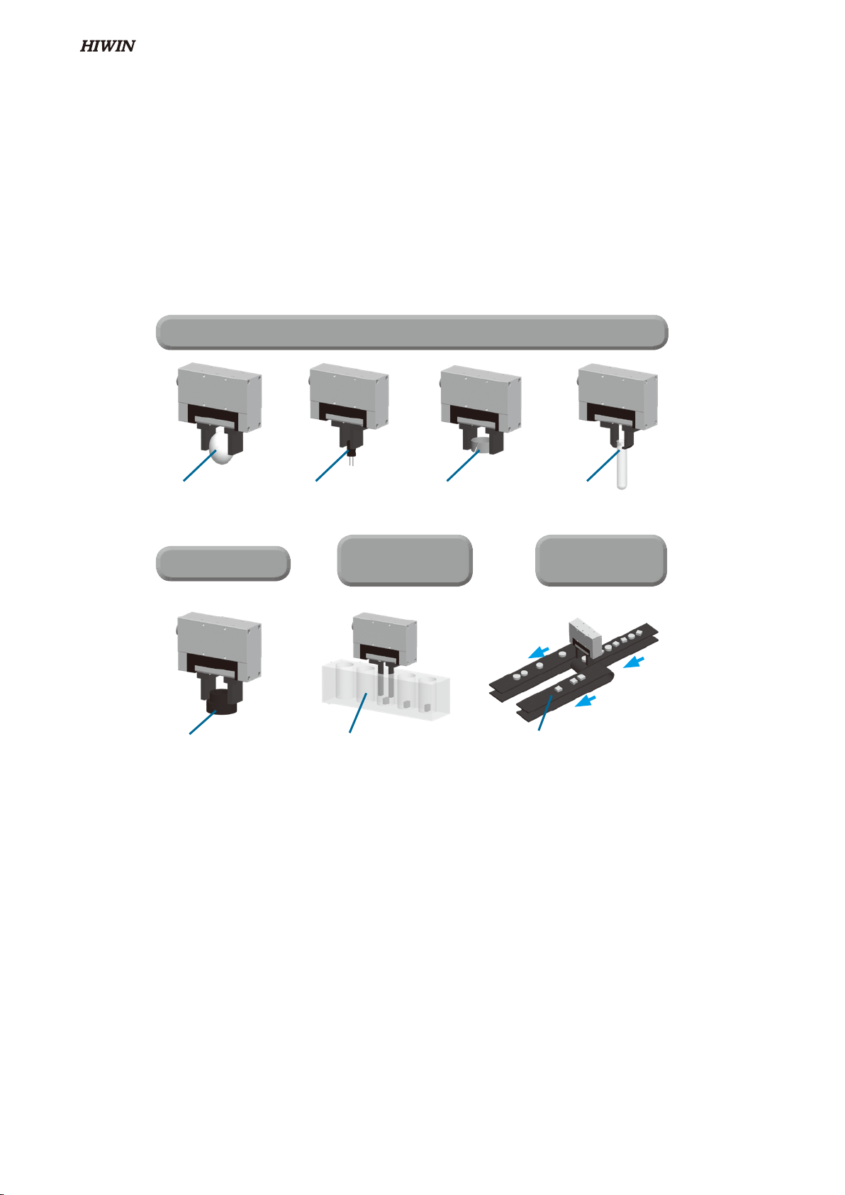
◎Please mount the product and jaws with
adequate screw tightening torque.
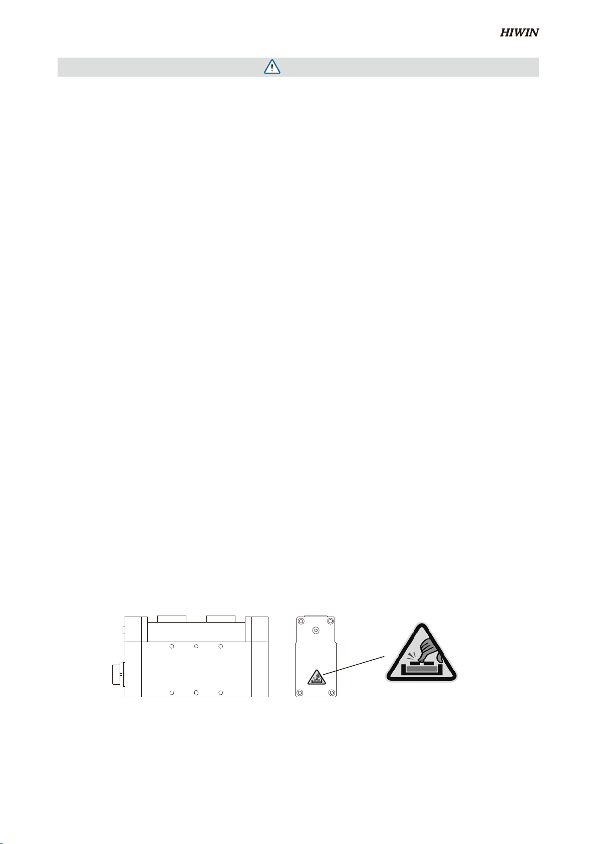
◎Please do not approach or touch the product
while the product is operating.
◎When a person is accidentally caught into
the machine, please turn off the power supply
immediately or push the emergency stop button
of external safety loop device, and then adjust the
jaws position or remove the jaws manually for
disengagement.
◎Do not touch the connectors or exposed
terminals of the controller. Doing so may result
in electric shock.
◎Turn off the power to the product in the event
of power failure. Failure to do so may cause the
product to suddenly start moving when the power
is restored, resulting in injury or product damage.
◎If the product is generating heat, smoke, a
strange smell or continual noise, turn off power
immediately. Continuing to use the product may
result in product damage or fire.
◎When the product gripping workpiece loses
the position coordinate, or the original point
return (RESET) cannot be performed due to the
product gripping workpiece after starting the
product, please move the product to the safe
area first, and then set the parameters of the
software interface (XEG-W1). In the JOG mode,
or in the reverse direction GRIP operation, after
confirming that the workpiece is released, then
performed the origin return.
◎If the product does not activate while gripping a
workpiece, please cut off the power immediately.
Remove the workpiece by adjusting the jaws
position or removing the jaws manually. After the
abnormal state is corrected restart the power.
◎Please do not grip live or hazardous objects.
◎Prevent load from applying force to one jaw
when gripping a workpiece.
◎When the product is activated, please do not
apply any external force on the gripper.
◎After the product output the HOLD signal, if the
GRIP command is executed, it is necessary to
confirm that the gripping stroke and whether
the motor are out of step, causing the workpiece
to fall.
Warning
equipment to ensure safety. When operating or
adjusting the gripper, be sure to observe safety
measures for the system.
◎Please do not disassemble, or modify the product
to avoid personal accident, electric shock, fire or
damage.
C02UE03-2007
2

Caution
◎Do not hold moving parts of the product or its
cables during installation. It may result in injury.
◎Do not insert a finger or object in the openings in
the product. It may cause fire, electric shock, or
injury.
◎The motor generates a large amount of heat
during operation, and the product surface
temperature is high. Ensure this will not affect a
workpiece near the gripper.
◎The actuator cables with the product are flexible,
but do not store the cables in a movable cable
duct that bends more than the specified bending
radius. (Rb ≥ 63mm )
◎Do not scratch the actuator cables. Please
perform periodic inspections monthly. Scratching,
forcible bending, straining, winding, and pinching
may cause short circuit and insulation failure,
which results in electric shock and malfunction.
◎When the product is unusable and scrapped,
please follow the local waste disposal regulations
for handling.
◎When using this product, please wear safety
shoes or the related protective equipment.
◎The mounting face has holes and slots for
positioning. Make use of them if necessary.
◎Design the jaws to be lightweight and minimum
length.
◎Mass of a workpiece that the jaws can grip
greatly differs depending on the material quality,
shape, and gripping surface condition of the jaws.
◎Use speed and parameters appropriate with the
product to avoid making a great impact to the
jaws.
◎Please assure there is sufficient space for
maintenance and inspection, and perform
regular maintenance every six (6) months or after
activating the product 500,000 times.
◎Please perform maintenance of transmission
components in manual mode. After adjusting the
gripper to the maximum opening position, please
use the greasing device to replenish the grease
or apply the grease on the screw shaft and both
sides of groove.
◎The measured result of actual noise level for
product is 61.2 dB. (Conditions: distance from
the product is 1 meter, height from the ground is
1.6 meters, maximum speed is 80% operating). If
the noise level is over 80dB(A) during operation,
personal protective equipment is required.
1.2 Warning Sign Location & Description
The warning sign shown below will be on the product to ensure the proper and safe operation.
Danger for Hand Injury
Please do not Insert Hand
C02UE03-2007 3

The warranty period for the product is 12 months or 5 million operations (whichever comes first), but it does
not include any of the following causes of failure:
◎Beyond the operation method, operating environment and storage specifications defined in the product
manual.
◎The damage caused by installation place movement, change of working environment, or improper transfer
after being installed by a professional installer.
◎Product damaged due to collision or accident caused by improper operation or installation.
The following conditions are not covered by the warranty.
◎Product serial number or date of production(month and year) can not be verified.
◎Gripper body and control components using non-Hiwin original products.
◎Adding or removing any element into/out the gripper or the controller.
◎Modifying the wire or the cables between the gripper body and the controller.
◎Any modification of the appearance of the gripper or controller; removal of the components inside the
gripper or the controller. e.g., demolition of the outer covering,product drilling or cutting.
◎Damage caused by any natural disaster. i.e., fire, earthquake, tsunami, lightning, windstorms, floods etc.
HIWIN does not provide any warranty or compensation to all the damage caused by above-mentioned
circumstances unless the user can prove that the product is defective.
For more information towards warranty terms and conditions, please contact the technician or the dealer who
you purchased with.
1.3 Warranty Coverage
C02UE03-2007
4

2.1 Features
2. Electric Gripper
• Gripping force control
- The gripping force can be set by increments of 1% in the range of 40 to 100%.
- Gently apply gripping force to components that are susceptible to deformation or damage.
• Position control
- The position setting and measurement can be adjusted by a minimum value of 0.01mm.
- Gripping position will be checked by the HOLD signal output to verify if the gripper is in the set
range.
• Speed control
- Motion speed can range from 1 to 100 mm/s by increments of 1 mm/s.
- Applies to fast tact times and low impacts.
Gripper Controller
Single Axis Robot
Stepper Motor
XEG-Series
- The whole series adopts stepper motor with encoder, which has signal output such as status
return, abnormal alarm and object identification.
- The use of a miniature both-hand linear module to achieve the advantages of high speed, high
precision, high rigidity, high efficiency and small size.
- Provide with intelligent functions such as origin return and gripping force model establishment,
adaptive capture and model adjustment, energy saving and tmeperature measurement.
- Direction of movement, stroke, gripping force and speed etc. can be set, and the operating
software has the function of using history record.
- Support serial and I/O signal communication, more flexible and convenient to use.
- All series achieve RoHS, uses lowest water pollution level(WGK1) grease and environmentally
friendly packaging materials(NBSK).
- In 2017, we won the Good Design Award in Japan and Taiwan Excellence Award.
Function Setting:
C02UE03-2007 5

2.2 Applications
Shell
structures
Electronic
components
Plastic or
Rubber
Glass or
Crystal
Measurement Gripping in a
narrow space
Detection /
Identification
Gripping of parts that are easily deformed or damaged.
Shape measurement Deep holes Selection and alignment
• Multi-point position control
- I/O signal communication mode: 31 or 62 group of action mode can be stored; Serial
communication mode: No limit for action group
• Identifying by position detection
- In I/O signal communication mode, provided 3 or 7 kinds of work object of the external size
detection and identification;In serial communication mode, the number of work object is not
limited and also the measurement size value can be fed back.
C02UE03-2007
6

2.3 Specifications
[Note 1] The weight of workpiece(kg) * acceleration of gravity 9.81(m/s2) should be 1/10~1/20 of the gripping force(N).If the
gripper holding a workpiece moves or turns with high-acceleration/deceleration, choose the model with higher
force allowance.
[Note 2] Set the parameters and operation mode to avoid application of excessive impact force to the attachments (fingers)
during operation.
[Note 3] Apply proper amount of grease to the grease hole of single axis robot by a grease supply device or on the surface of
ball screws with brushes, XEG-32-PR clean and oil the drive guide shafts regularly.
[Note 4] Mass of a workpiece that the attachments (fingers) can grip greatly differs depending on the material quality, shape,
and gripping surface condition of the attachments (fingers). Design the attachments (fingers) to be lightweight and
minimum length.
[Note 5] The gripping force of the specification sheet is measured at a speed of 2mm/s and a gripping point(L) of 20mm.
The accuracy of the maximum gripping force is XEG-16:±30%、XEG-32:±16.6%、XEG-48:±15%、XEG-64:
±13.3%、XEG-32-PR:±20%.
Model XEG-16 XEG-32 XEG-48 XEG-64 XEG-32-PR
Electric
Gripper
Stroke [both sides] (mm) 16 ±0.5 32 ±0.5 48 ±0.5 64 ±0.5 32 ±0.5
Gripping Force (N) 25~50 60~150 135~270 180~450 75~150
Speed (mm/s)
Motion 1~60 1~80 1~80 1~100 1~60
Gripping [Note 2] 1~10 1~20 1~20 1~20 1~10
Repeatability (mm) ±0.01 ±0.01 ±0.02 ±0.02 ±0.01
Weight (kg) 0.4 0.7 1.5 1.9 1.1
IP Class IP20 IP65
Cleanroom Class ISO Class 5 (Class 100) ISO Class 3
(Class 1)
Drive Device Single-Axis Robot
Grease Supply of Drive Device
[Note 3] 500,000 cycles or 6 months
Impact/Vibration Resistance
(m/s2)150 / 30
Operating Temperature Range
(。C) 5 ~ 45
Operating Humidity Range (%) RH 35~85 (No condensing)
C02UE03-2007 7

2.4 System Construction
I/O Cable (14 pins)
Actuator Cable
Actuator Cable
USB Cable
USB Cable [Note 4]
PC (Self Prep.)+XEG.dll
• Communication method:I/O signal
• Communication method:Serial Communication RS232
Power Cable
Power Cable
Power Supply
(DC 24V)
Power Supply
(DC 24V)
Controller
Controller
Electric Gripper
Electric Gripper
or
or
PC (Self Prep.) + Software Upper Controller (Self Prep.)
Upper Controller (Self Prep.)
PLC
C02UE03-2007
8

[Note 1] Actuator cable length: 1.5m (standard), 3m, 5m.
[Note 2] I/O cable length: 1.5m (standard), 3m, 5m or produced upon receipt of order.
[Note 3] USB cable length: 1.5m (standard)
[Note 4] If control the electric gripper with serial communication RS232, a special USB cable is required. Please specify when
ordering.
[Note 5] Power supply plug only.
[Note 6] The RS485 cable (RJ45) is an optional accessory. There are two specifications for the cable length, 0.5M and 5M,
please specify when ordering.
[Note 7] XEG Dynamic-Link Library (.dll) and user manual, please visit HIWIN official website to download.
[Note 8] Please download the MODBUS manual from the HIWIN website.
RS485
Cable
RS485
Cable
PLC (Self Prep.)
Upper Controller
(Self Prep.)
or
or
Power Cable
(Up to 15
units)
Power Supply (DC 24V)
(Self Prep.)
Actuator Cable Actuator Cable
Electric Gripper Electric Gripper
HMI (Self Prep.)
Controller
• Communication method:Serial Communication Modbus RTU
Controller
C02UE03-2007 9

2.5 Specification Illustration
[Note 1] Left side connector of the actuator cable connects to the electric gripper, and right side connector of the actuator
cable connects to the controller.
[Note 2] XEG-W2 can support XEG-C1 and XEG-C2, please visit HIWIN official website to download.
[Note 3] Please refer to HIWIN official website "TM quick installation guide".
https://www.hiwin.tw/download/tech_doc/ee/TM_Plug&Play_Version.pdf
[Note 4] Please refer to HIWIN official website "UR+ Technical Manual Guide".
https://www.hiwin.tw/download/tech_doc/ee/UR_Plus_Technical_Manual_Guide.pdf
The model number of Electric Gripper series contains the type, size, other kinds of cable
length or special order,etc..
XEG - 16 - C2 10 1 - W2 - S
A B C D E F G
1500 mm
3000 mm
3000 mm
5000 mm
1500 mm
5000 mm
10
30
1L
3L
50 5L
Code Item Illustration
AType XEG:2-finger type
BModel
16:total stroke is 16 mm
32:total stroke is 32 mm
48:total stroke is 48 mm
64:total stroke is 64 mm
32PR:total stroke is 32 mm (ISO Class 3, IP65)
CController C1:controller (Communication:I/O, USB)
C2:controller (Communication:I/O, Modbus RTU)
DActuator Cable Length and
Connector Type [Note1]
10:1.5M (Standard)
1L:1.5M-Right Angle type
30:3.0M
3L:3.0M-Right Angle type
50:5.0M
5L:5.0M-Right Angle type
EI/O Cable Length
1:1.5M (Standard)
3:3M
5:5M
FController Setting Kit W2:software [Note 2]
GNote
S:Customized order
TM:TM Plug & Play Version [Note 3]
UR:UR+ Solutions [Note 4]
SC:USB cable for serial communication
C02UE03-2007
10

A.When using the thread on the body
B.When using the thread on the mounting plate
C.When using the thread on the back of the body
2.6 Mounting Method
固定方向 固定方向
定位銷
固定方向
定位銷
定位銷
Mounting Direction
Positioning pin
Positioning pin
Positioning pin
Mounting
Direction
固定方向
定位銷
定位銷
Mounting
Direction
固定方向 固定方向
定位銷
固定方向
定位銷
定位銷
Mounting Direction
Positioning pin
Positioning pin
Positioning pin
Mounting
Direction
固定方向
定位銷
定位銷
Mounting
Direction
固定方向 固定方向
定位銷
固定方向
定位銷
定位銷
Mounting Direction
Positioning pin
Positioning pin
Positioning pin
Mounting
Direction
固定方向
定位銷
定位銷
Mounting
Direction
[Note 1] Do not drop or hit the gripper when mounting to avoid scratches and dents. It might cause the deterioration of accuracy
and operation failure.
[Note 2] Tighten the mounting screw of the products with the specified torque.
[Note 3] Tighten the mounting screw of the attachments (fingers) with the specified torque as below table.
[Note 4] The mounting face has holes and slots for positioning. Make use of them if necessary.
Model Bolt Recommended tightening
torque (N*m)
XEG-16 M2.5x0.45P 0.4~0.6
XEG-32 M3x0.5P 0.6~0.8
XEG-48
XEG-64 M5x0.8P 2.8~3.4
Model Bolt
Recommended
tightening
torque (N*m)
Effective
depth (mm)
XEG-16 M3x0.5P 0.6~0.8 8
XEG-32 M4x0.7P 1.2~1.6 10
XEG-48
XEG-64 M6x1P 4.6~5.2 12
Model Bolt Recommended tightening torque
(N*m) Effective depth (mm)
XEG-16 M3x0.5P 0.6~0.8 5
XEG-32 M3x0.5P 0.6~0.8 4
XEG-32-PR M3x0.5P 0.6~0.8 5
XEG-48
XEG-64 M3x0.5P 0.6~0.8 8
Model Bolt
Recommended
tightening
torque (N*m)
Effective
depth (mm)
XEG-16 M3x0.5P 0.6~0.8 3.5
XEG-32
XEG-32-PR M4x0.7P 1.2~1.6 4.5
XEG-48
XEG-64 M6x1P 4.6~5.2 8
C02UE03-2007 11

2.7 Maintenance
2.7.1 Applying Grease to Single Axis Robot
2.7.2 Greasing Device for Electric Gripper
The greasing device for electric gripper includes grease gun, grease nozzle adaptor, grease
nozzle and lubricating grease which are available for customers to select based on their usage
requirements.
Ø6
(Ø1.8)
Ø6
20
Ø6
Ø6
120 11
PT 1/8
13
Ø6
5M5x0.5P
Ø4
25
5
M5x0.5P
M5x0.5P
M5x0.5P
25
5
25
5
140
Grease nozzle adaptor
Grease nozzle
Ø2
XEG-16 XEG-32, XEG-48, XEG-64
◎Apply proper amount of grease to the grease hole
of single axis robot with a grease supply device or
on the surface of ball screws with brushes.
◎When mounting the fingers, a grease passage on
the fingers may be necessary.
◎Turn off power supply after adjusting the gripper to
the maximum opening position; or under the power
off condition, adjusting the gripper to the maximum
opening position manually after removing the bolt
on the manual adjustment part.
◎After removing the bolts on the dust cover, align
the nozzle of greasing device to the grease holes
shown in the figure below, and then proceed the
lubrication maintenance.
XEG-32-PR
◎Turn off power supply after adjusting the gripper to
the maximum opening position to clean and oil of the
drive guide shafts .
Drive guide shafts
Fingers
Grease passage
Grease hole (Ø2)
Grease hole (Ø2)
(Ø2)
(Ø2)
Manual
adjustment
Manual
adjustment Manual
adjustment
注脂孔
手動調整部
夾具
注脂孔
手動調整部 手動調整部
注脂孔
Fingers
Grease passage
Grease hole (Ø2)
Grease hole (Ø2)
(Ø2)
(Ø2)
Manual
adjustment
Manual
adjustment
Manual
adjustment
注脂孔
手動調整部
夾具
注脂孔
手動調整部 手動調整部
注脂孔
Fingers
Grease passage
Grease hole (Ø2)
Grease hole
(Ø2)
(Ø2)
(Ø2)
Manual
adjustment Manual
adjustment
Manual
adjustment
注脂孔
手動調整部
夾具
注脂孔
手動調整部 手動調整部
注脂孔
C02UE03-2007
12

Model no. Dimensions
GT-PT1/8-M5
Model no. Dimensions Lubricating Type
GNZ-L-M5 Minimized grease hole
GNZ-C1-M5
Nipple
(M3 Thread)
Ø6
(Ø1.8)
Ø6
20
Ø6
Ø6
120 11
PT 1/8
13
Ø6
5M5x0.5P
Ø4
25
5
M5x0.5P
M5x0.5P
M5x0.5P
25
5
25
5
140
Grease nozzle adaptor
Grease nozzle
Ø2
It is recommended that lubricating
grease used for the electric gripper have high
wear resistance, low friction resistance and
water resistance such as HIWIN G04 or other
lubricating grease with similar features.
If it is used in a clean room environment,
it is recommended to use HIWIN G03 with
low particle emitting rate or other lubricating
grease with similar features.
• Grease Gun (Optional Item)
• Grease Nozzle Adapter
• Grease Nozzle
• Lubricating Grease for Electric
Gripper (Optional Item)
Model
no. GN-80M GN-400C
Dimen-
sions
Spec.
1. Working pressure: 15 MPa
2. Output: 0.5~0.6 c.c./Stroke
3. Weight: 520 g(grease excluded)
4. Grease reload: 70 g flexible tube or 120 ml bulk loading
1. Working pressure: 15 MPa
2. Output: 0.8~0.9 c.c./Stroke
3. Weight: 1150 g (grease excluded)
4. Grease reload: 14 o.z. cartridge pipe or 400 ml bulk loading
222
(108) 320
(108) (20)
Ø10
彎管注油嘴
Ø10
彎管注油嘴
(20)
Nozzle Nozzle
Ø6
(Ø1.8)
Ø6
20
Ø6
Ø6
120 11
PT 1/8
13
Ø6
5M5x0.5P
Ø4
25
5
M5x0.5P
M5x0.5P
M5x0.5P
25
5
25
5
140
Grease nozzle adaptor
Grease nozzle
Ø2
M5x0.5P
6
13
5
Grease HIWIN G03 HIWIN G04
Color Cream Cream
Base Oil Synthetic
hydrocarbon oil Lipid/PAO
Thickener Special calcium soap Lithium Soap Based
Applicable
Temperature(℃)-45~125 -35~120
Dropping Point(℃)>210 >225
Penetration (0.1mm) 265-295 260-280
Viscosity(cst) 40℃30 25
100℃5.9 6
4 ball test (ASTM D2266) 366 μm 418 μm
C02UE03-2007 13

3.1 Controller Specifications
3.2 Names and Functions of Parts
3. Electric Gripper Controller
CN3
CN2
CN1
DC 24V
I/O電纜線
USB傳輸線
驅控電纜線
電源線
I/O Cable
USB Cable
Actuator Cable
Power Cable
Item Specifications
XEG-C1 XEG-C2
Compatible Motor Stepper motor
Compatible Encoder Optical rotary encoder
Min. Setting Position (mm) 0.01
Power Supply (V) DC 24 ±10%
Total Current (A) 0.5A
Operating Temperature Range (℃)5 ~ 45
Operating Humidity Range (%) RH 35~85 (No condensing)
IP Classification IP20
Weight (kg) 0.15 0.3
Number of Points
External I/O 30 points +original point 62 points +original point
Serial
Communication Not limited Not limited
External I/O Input 5 points: Command point setting
1 point: Command input
6 points: Command point setting
1 point: Command input
1 point: Firmware version update
Output 6 points: Control output 8 points: Control output
Serial Communication RS232 (USB) RS485 (Modbus-RTU)
LED Indicator
24V Power supply lamp:
(PWR: green)
24V Power supply lamp:
(PWR: green)
Error status lamp: (ALM: red) Error status lamp: (ALM: red)
5V Power supply lamp: (USB: green)
Emergency stop lamp: (EMG: red)
Safety Circuit N/A Trigger emergency stop (Servo OFF)
ID Setting N/A Rotary DIP switch (0~F), 15 stations
Terminal Resistor N/A 120Ω
3.2.1 XEG-C1
Name Illustration
PWR Power supply lamp (Green)
ALM Error status lamp (Red)
24V/0V Power supply terminal
CN1 Actuator terminal
CN2 Communication terminal
CN3 I/O connector
C02UE03-2007
14

3.2.2 XEG-C2
Code Part Name Illustration
PWR 24V Power supply lamp (Green) Lights after 24V / 0V power input
ALM Error status lamp (Red) Lights after error status occurs [Note 1]
USB 5V Power supply lamp (Green) Lights after USB cable is connected
EMG Emergency stop lamp (Red) Lights after emergency stop trigger
CN1 Power terminal and Emergency
stop terminal Connect power supply and emergency stop [Note 2]
CN2 Actuator terminal Connect actuator cable
CN3 Communication terminal Connect USB cable
CN4 Communication terminal Connect RS485 cable [Note 3]
CN5 Communication terminal Connect RS485 cable [Note 3]
CN6 I/O signal terminal Connect I/O cable
CN7 Station channel Set controller station number [Note 4]
CN8 Terminal resistor Two-stage switch, left direction is off, right direction
is on [Note 5]
[Note 1] The display mode of the ALM indicator in each abnormal state is as follows:
[Note 2] The description and wiring diagram of the power connector are as follows. When EMG + and EMG- are
disconnected, the emergency stop function is activated (Servo off) , and the electric gripper stops immediately.
[Note 3] The pin definition of the RS485 cable is as follows. Please use EIA-485 as the reference, use twisted pair
cables and recommend TIA/EIA CAT5e or more. A maximum of 15 controllers can be connected in series, and
the longest serial cable length is 50 meters in total.
Error Status ALM Indicator
1. Position fault After every 1 second, ALM indicator blinks 1 time
2. Over travel After every 1 second, ALM indicator blinks 2 times
3. Original point fault After every 1 second, ALM indicator blinks 3 times
4. Trigger emergency stop After every 1 second, ALM indicator blinks 4 times
5. Firmware version update Continuous flashing
PIN Define Color
1 N/A White/Orange
2 GND Orange
3 D+ White/Green
4 N/A Blue
5 GND White/Blue
6 D- Green
7 N/A White/Brown
8 N/A Brown
1 2 3 4 5 6 7 8
C02UE03-2007 15

3.3 I/O Connector Illustration
No. I/O Symbol Function
A1
Input
IN0 Position data bit0
A2 IN1 Position data bit1
A3 IN2 Position data bit2
A4 IN3 Position data bit3
A5 IN4 Position data bit4
A6 START Command input
A7 COM+Common ground(+)
A1 A2 A3 A4 A5 A6 A7
B1 B2 B3 B4 B5 B6 B7
[Note 4] The station number can be set up to 15 (1~F) at most, and station number 0 is Broadcast Mode, which is only
used in specific situations. The station number cannot be repeated in a single serial network. After setting the
station number, you have to power off and restart. The following is an example where the station number (ID)
is set to 15 (F):
[Note 5] When two or more controllers are connected in series and the total cable length is more than 10 meters, the
last controller must have the terminating resistor function enabled. The host system needs to be connected
with a terminating resistor (120Ω) between the two signal wires. The system wiring is as follows:
[Note 6] In order to reduce signal interference, please ground the controller's locking surface and avoid the signal
cable approaching the high-voltage circuit.
1
0
2
3
4
5
6
7
8
9
A
B
C
D
E
F
Function Setting
CN7 CN8 CN7 CN8 CN7 CN8 CN7 CN8
Station Number No.1 No.2 No.3 No.4
Terminal Resistor OFF OFF OFF ON
XEG
上位
控制器 -C2
(No.1)
XEG-C2
(No.2)
XEG-C2
(No.3)
XEG-C2
(No.4)
CN7 CN8 CN7
=120Ω
R
D-
D+
1
0
2
3
4
5
6
7
8
9
A
B
C
D
E
F
1
0
2
3
4
5
6
7
8
9
A
B
C
D
E
F
1
0
2
3
4
5
6
7
8
9
A
B
C
D
E
F
1
0
2
3
4
5
6
7
8
9
A
B
C
D
E
F
XEG
上位
控制器 -C2
(No.1)
XEG-C2
(No.2)
XEG-C2
(No.3)
XEG-C2
(No.4)
CN7 CN8 CN7
=120Ω
R
D-
D+
1
0
2
3
4
5
6
7
8
9
A
B
C
D
E
F
1
0
2
3
4
5
6
7
8
9
A
B
C
D
E
F
1
0
2
3
4
5
6
7
8
9
A
B
C
D
E
F
1
0
2
3
4
5
6
7
8
9
A
B
C
D
E
F
XEG
上位
控制器 -C2
(No.1)
XEG-C2
(No.2)
XEG-C2
(No.3)
XEG-C2
(No.4)
CN7 CN8 CN7
=120Ω
R
D-
D+
1
0
2
3
4
5
6
7
8
9
A
B
C
D
E
F
1
0
2
3
4
5
6
7
8
9
A
B
C
D
E
F
1
0
2
3
4
5
6
7
8
9
A
B
C
D
E
F
1
0
2
3
4
5
6
7
8
9
A
B
C
D
E
F
XEG
上位
控制器 -C2
(No.1)
XEG-C2
(No.2)
XEG-C2
(No.3)
XEG-C2
(No.4)
CN7 CN8 CN7
=120Ω
R
D-
D+
1
0
2
3
4
5
6
7
8
9
A
B
C
D
E
F
1
0
2
3
4
5
6
7
8
9
A
B
C
D
E
F
1
0
2
3
4
5
6
7
8
9
A
B
C
D
E
F
1
0
2
3
4
5
6
7
8
9
A
B
C
D
E
F
XEG
上位
控制器 -C2
(No.1)
XEG-C2
(No.2)
XEG-C2
(No.3)
XEG-C2
(No.4)
CN7 CN8 CN7
=120Ω
R
D-
D+
1
0
2
3
4
5
6
7
8
9
A
B
C
D
E
F
1
0
2
3
4
5
6
7
8
9
A
B
C
D
E
F
1
0
2
3
4
5
6
7
8
9
A
B
C
D
E
F
1
0
2
3
4
5
6
7
8
9
A
B
C
D
E
F
3.3.1 XEG-C1
Host
system
C02UE03-2007
16

Code Wire Color I/O Define Function
I1 Black
Input
IN0 Position data bit0
I2 Red IN1 Position data bit1
I3 Yellow IN2 Position data bit2
I4 Blue IN3 Position data bit3
I5 Gray IN4 Position data bit4
I6 Pink IN5 Position data bit5
I7 Light Blue START Command input
I8 Red / Black BOOT Firmware version update
I9 Brown / Black - COM+ Common ground (+)
O1 Green / Black
Output
POS Position check
O2 Orange HOLD Gripping range check
O3 Brown BUSY Executing command
O4 Green ALM-CODE1 Error status number
O5 Purple ALM-CODE2
O6 White CHK-CODE1
Identification numberO7 Light Green CHK-CODE2
O8 Yellow / Black CHK-CODE3
O9 White / Black - COM- Common ground (-)
[Note 1] After the controller firmware version is V2.0.16(inclusive), when the pins of A6,A7 and B7 are connected to
0V,24V and 0V respectively, the firmware version update mode is entered, and the controller status abnormality
indicator is displayed. (ALM) will continue to flash. For more details, please refer to the "XEG-C1 Firmware
Update User's Manual".
3.3.2 XEG-C2
No. I/O Symbol Function
B1
output
BUSY Executing command
B2 HOLD Gripping range check
B3 ALM-CODE1
Error status number
B4 ALM-CODE2
B5 CHK-CODE1
Identification number
B6 CHK-CODE2
B7 COM-Common ground(-)
C02UE03-2007 17
This manual suits for next models
5
Table of contents
Other Hiwin Industrial Equipment manuals
Popular Industrial Equipment manuals by other brands

Morgana
Morgana AutoCreaser Pro 33A instruction manual

Ossila
Ossila Slot-Die Coater user manual

Watts
Watts 994-FS Series INSTRUCTION, INSTALLATION, MAINTENANCE AND REPAIR MANUAL

Emerson
Emerson AS2-ACC Series RE-ASSEMBLY INSTRUCTIONS

Tractel
Tractel tirak Original manual

Edwards
Edwards CDP instruction manual