NJD Electronics Q-PEDAL User manual

Features of the Q-pedal
• Foot operated lighting controller
• Robust extruded aluminium case
• Four Channel Sound Chaser
• FLOOD and BLACKOUT.
• Individual Channel Indication
• Two F321 Output Sockets
• Interference free switching
Q-PEDAL

User Guide Q-PEDAL
IMPORTANT
Installer and Users please note:
These instructions should be read carefully and left with
the user of the product for future reference.
Installation
The Q-pedal is not fitted with a mains plug. This is because:
a) it is capable of controlling more than 13 Amps
b) it is an appliance for professional use.
Connect the Q-pedal to the mains supply with the built in mains
lead, Connect the wires as follows:
• Brown = live
• Blue = neutral
• Green/yellow = earth
• The Q-pedal must be earthed
Connect the output loads to the F321 sockets on the rear
panel using type F321BA plugs. Both sockets are connected the
same. Connections are shown below. Each channel of each socket
has its own 5 Amp fuse, so loads of more than 1150W per
channel should be distributed over
the two sockets.
(It is good practice to distribute any
load so that both sockets are
supplying approximately equal
amounts of power).
If connecting any other load than
filaments lamps, it should first be ascertained that the load is
suitable for switching on and off rapidly.
If used with a 16A or 20A supply then the internal Maximum
Current switch must be set accordingly.
Disconnect from the mains supply. Remove the left-hand end
cover (the opposite end to the mains cable) by removing the four
Torx screws using a Torx T20 Screwdriver. Slide out the fascia
panel. Move the 13A/20A switch (located adjacent to the "output
Earth
1
23
4
LIVE LIVE
Neutral Neutral
© NJD Electronics 2003 -Page 2-

mimic" LEDs) to the 20A position. Replace the fascia panel, and
the end cover.
• For a 20A supply, the maximum total load is 4600W
which can be made up of:
either: 1150W watts on each of the four channels
or: different loads on each channel so that the total does not
exceed 4600W (but not more than 2300W on any one channel)
or: loads of up to 2300W may be connected to all four
channels provided that the unit is operated so that the total load
that is switched on at any one time does not exceed 4600W.
If connected to a lower capacity supply, or by a standard
British 13Amp BS1363 plug and socket, the output must be
reduced as follows:
•For a 16A supply, the maximum total load is 3680W
which can be made up of:
either: 920W watts on each of the four channels
or: different loads on each channel so that the total does not
exceed 3680W (but not more than 2300W on any one channel)
or: loads of up to 2300W may be connected to all four
channels provided that the unit is operated so that the total load
that is switched on at any one time does not exceed 3680W.
•For a 13A supply, the maximum total load is 2990W
which can be made up of:
either: 745W watts on each of the four channels
or: different loads on each channel so that the total does not
exceed 2990W (but not more than 2300W on any one channel)
or: loads of up to 2300W may be connected to all six
channels provided that the unit is operated so that the total load
that is switched on at any one time does not exceed 2990W.
Inductive loads:
If connecting inductive loads such as motors or discharge
lighting (metal halide, fluorescent or neon) to the Q-pedal, make
sure that the VA rating of the load does not exceed the figures
above (1150VA per channel, 3450VA total). The VA rating should
be labelled on the apparatus being connected. If the VA rating is
not known, reduce the maximum handling capacity to 800W per
channel, and 2400W total.
User Guide Q-PEDAL
© NJD Electronics 2003 -Page 3-
High-inrush loads.
If connecting high inrush loads, such as halogen lamps or
apparatus incorporating a transformer, reduce the handling
capacity to 1500W per channel.
Intelligent Lighting Effects.
It is not recommended to switch intelligent effects (such as
NJD Predator, Datamoon, etc) from the Q-pedal. These units
should be connected directly to the mains supply (via an isolating
switch) and left running all the time that the installation is
switched on. A controller (either a DMX controller such as Merlin
or IQ-MX80, or a remote control such as AR1) should be used to
switch the effects from operating to standby. This avoids the delay
of up to half a minute caused by the internal electronics
performing its setting up procedure, which happens with all
intelligent motorized lighting effects.
Sound input
The Q-pedal has in internal microphone, so no connection to
the audio source is required. However, when mounted on the floor
it is likely to pick up sounds from the stage or the sound of the
push-buttons being used. For this reason, it is possible to disable
the internal microphone and connect an external sound signal. To
disable the internal microphone, disconnect from the mains
supply. Remove the left-hand end cover (the opposite end to the
mains cable) by removing the four Torx, screws using a Torx T20
Screwdriver. Slide out the fascia panel. Move the Microphone
switch (located adjacent to the jack socket) to the OFF position.
Replace the fascia panel, and the end cover.
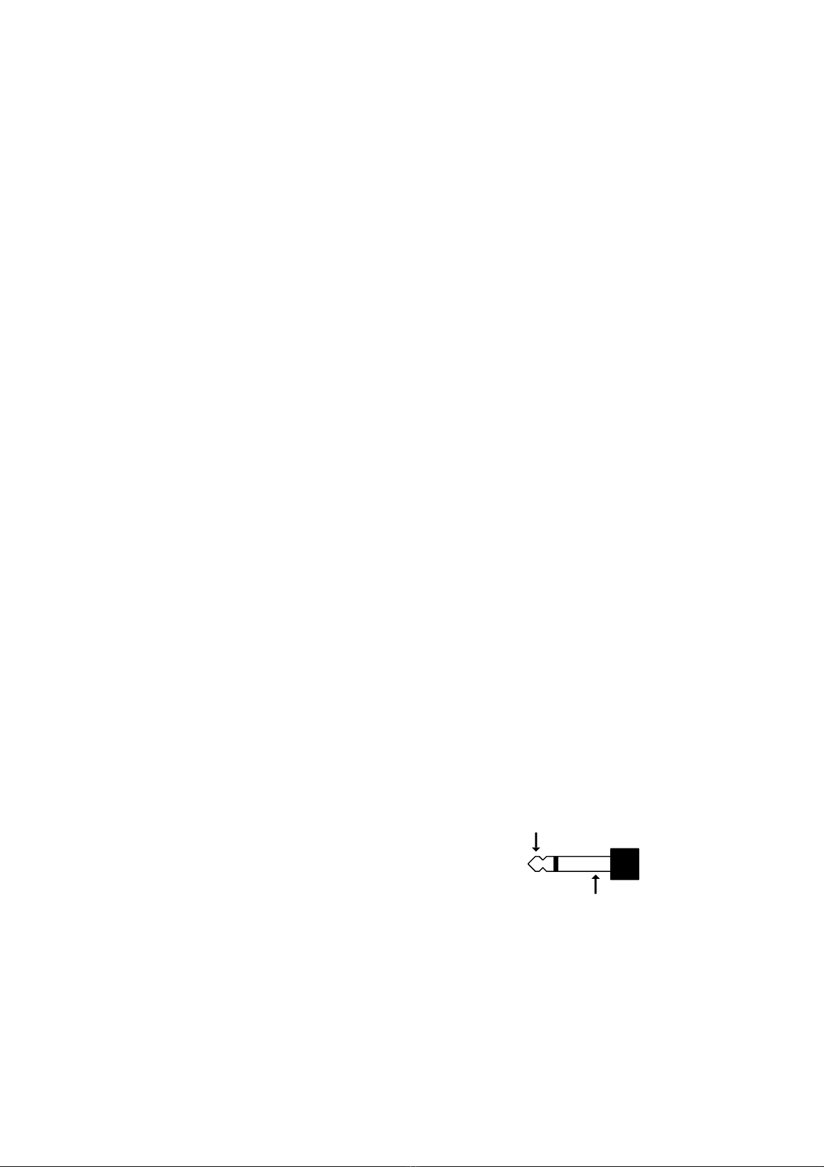
Connect an audio signal from the speaker output of a power
amplifier to the ¼” jack on the right hand end panel labelled
‘sound’. The sound input has an impedance of
3300Wso that it does not affect the
loudspeaker/amplifier loading. Voltages
greater than 50V rms may NOT be
connected to a jack plug, so the largest
amplifier that may be connected would be a
stereo amplifier that gives 1000W into 4W
User Guide Q-PEDAL
© NJD Electronics 2003 -Page 4-
signal
Ground

(500W per channel), or 600W into 8W(300W per channel).
The sound input requires a signal of at least 1.5V rms before
it will start to operate (about ½W into 4W). This means that the
sound-chase may not operate at low levels. (½W is about
96dB(A) on an average pair of PA speakers)
OPERATION
When first switched on,the Q-Pedal will be in blackout mode,
with the Blue LED lit. The chaser will be running (as shown on the
green LEDs to the right of the panel) but will not be connected to
the outputs.
FLOOD.
Pressing the Flood switch will switch all four channels on to
give a floodlight effect. The yellow LED illuminates to show that
FLOOD has been selected. The Q-Pedal has internal mains current
monitoring, so that if the mains current exceeds 13A (or 20A
depending on the setting of the internal Max. Current switch) the
fourth channel will be switched off to keep the current within
operating limits.
BLACKOUT.
Pressing the blackout switch turns all four channels off. The
blue LED illuminates to show that BLACKOUT has been selected.
The chaser continues to run although not connected to the
output, so that a new pattern can be selected whilst the outputs
are off.
CHASE.
Press the chase button twice to select chase. The chase
speed will be determined by the time between the two switch
presses. (Press twice in quick succession for a fast chase). The
CHASE LED illuminates green whilst it is waiting for the second
switch press, then red when in chase mode. The slowest chase
speed is 2.5 seconds between changes.
PATTERN.
The pattern switch selects the next chase pattern from a
choice of 12. The pattern may be changed at any time. The four
pattern LEDs show the selected pattern, so that patterns can be
User Guide Q-PEDAL
© NJD Electronics 2003 -Page 5-
Table of contents


