NKK SWITCHES IS-L0204-CS User manual
LCD 36x24 Logic Boards User Manual G.docx
www.nkkswitches.com • engineering@nkkswitches.com
Page 1 of 24
0821
LCD 36x24 Logic Boards User Manual
LCD 36x24 Logic
Boards User Manual
Revision G
All Rights Reserved Worldwide
NKK Switches makes no warranty for the use of these products and assumes no responsibility for any errors, which may
appear in this document, nor does it make a commitment to update the information contained herein.
SmartDisplay is trademark of NKK Switches.

LCD 36x24 Logic Boards User Manual G.docx
www.nkkswitches.com • engineering@nkkswitches.com
Page 2 of 24
0821
LCD 36x24 Logic Boards User Manual
7850 East Gelding Drive • Scottsdale, AZ 85260-3420
TABLE OF CONTENTS
Contents
LCD 36x24 Logic Boards User Manual ................................................................................................ 1
1. What are Logic Boards?........................................................................................................................ 3
2. Standard Part Numbers ....................................................................................................................... 4
3. Connectors ............................................................................................................................................. 5
5. Board Dimensions................................................................................................................................. 9
6. Schematics............................................................................................................................................ 15
7. Key Terms & Definitions.................................................................................................................... 23
Warranty................................................................................................................................................... 24

LCD 36x24 Logic Boards User Manual G.docx
www.nkkswitches.com • engineering@nkkswitches.com
Page 3 of 24
0821
LCD 36x24 Logic Boards User Manual
7850 East Gelding Drive • Scottsdale, AZ 85260-3420
1. What are Logic Boards?
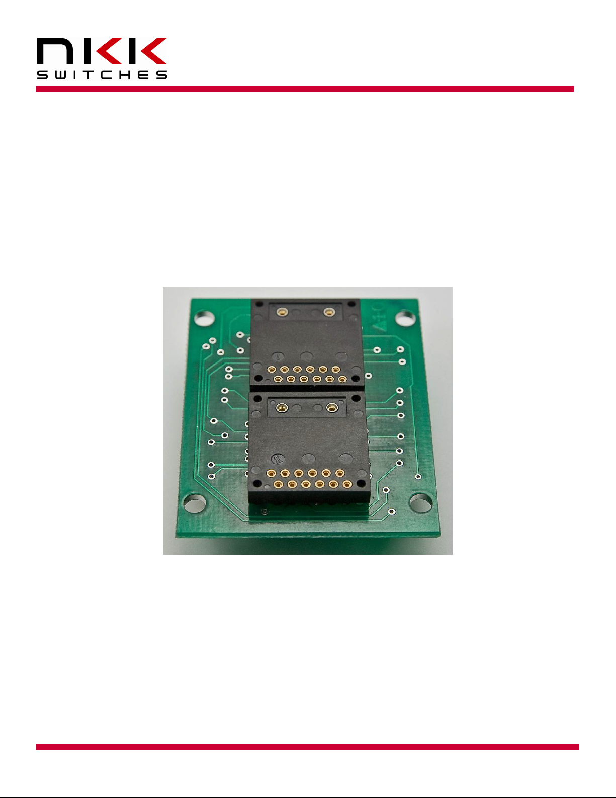
Logic Boards are switch panel that have glue logic to convert addressing and switch scanning to serial.
A Logic Board can be designed for any number of switches. The Logic Boards can be daisy-chained
using 14 pin ribbon cable hence allowing variable number of switches to be controlled via one port from
a controller.
Logic Board with any number of switches can be designed. Daisy-chain capability of the Logic
Boards allow the switches to be mounted at desire locations on the control panel.
The switches/displays can be soldered directly to the Logic Board or mounted on a sockets.

LCD 36x24 Logic Boards User Manual G.docx
www.nkkswitches.com • engineering@nkkswitches.com
Page 4 of 24
0821
LCD 36x24 Logic Boards User Manual
7850 East Gelding Drive • Scottsdale, AZ 85260-3420
2. Standard Part Numbers
The Logic Boards listed below are production parts. There are prototype boards that are not listed.
Additionally, NKK Switches will work with customers to design and build custom logic boards.
Item
Part number
with socket
and switch
Part number with switch
Description
1
-
IS-L0107-IS15BBFB4PRGB
Logic Board, LCD 36x24 RGB, 1SW.
Panel Mount
2
IS-L0204-CS
IS-L0204-S
LOGIC BOARD, 1x2, LCD 36x24 RGB, 2SW.
Side by side stackable
3
IS-L0271-CS
IS-L0271-S
LOGIC BOARD, 1x2, Compact LCD 36x24 RGB, 2SW.
Side by side stackable
4
IS-L0403-CS
IS-L0403-S
LOGIC BOARD, 2x2, LCD 36x24 RGB, 4SW.
Side by side stackable
5
IS-L1602-CS
IS-L1602-S
LOGIC BOARD, 4x4, LCD 36x24 RGB, 16SW.
Side by side stackable
There is a signal booster for when too many Logic Board are used in a daisy chain or very long cable are used for
interconnect.
Item
Part#
Description
1
IS-LBUF01
Signal booster for both LCD36x24 and LCD64x32
Note: Make sure the power is off when connecting or disconnecting the Logic Boards to or from
the controller or each other.
Note: Connecting the Logic Boards improperly could damage either/both the Logic Boards
and controller.
LCD 36x24 Logic Boards User Manual G.docx
www.nkkswitches.com • engineering@nkkswitches.com
Page 5 of 24
0821
LCD 36x24 Logic Boards User Manual
7850 East Gelding Drive • Scottsdale, AZ 85260-3420
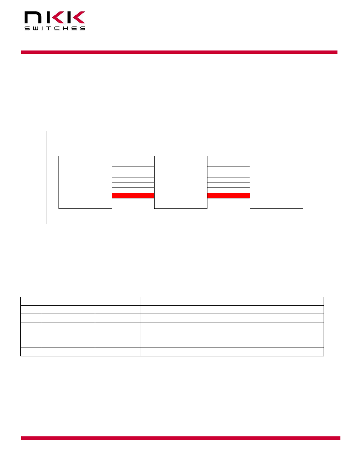
Illustration 1, Logic board connections
RIBBON RIBBON
CONTROLLER
LOGIC BOARD 1
LOGIC BOARD 2
3. Connectors
The SmartDisplay Controller connects to the J1 of the first logic board via 14 pin ribbon cables. The J2 of
the first logic board connect to J1 of the second logic board and so on. The switch numbering start with
switch one of the first Logic Board. The first switch of the next Logic Board will be one higher than the
last switch of the previous Logic Board.
J1
PIN 1
CABLE 1
J1 J2
PIN 1 PIN 1
CABLE 2
J1
PIN 1
Note: Attaching the ribbon cable without the red line on pin 1 on each of the headers may
cause damage to the controller or the logic board.
Ribbon Cables
These cables are used for connecting Logic Boards and the controller
Item
Part#
Length
Description
1
ISDCB81.2
1.2”
RIBBON CABLE, 14 CONDUCTORS, 28AWG, .050"
2
ISDCB83
3”
RIBBON CABLE, 14 CONDUCTORS, 28AWG, .050"
3
ISDCB88
8”
RIBBON CABLE, 14 CONDUCTORS, 28AWG, .050"
4
ISDCB812
12”
RIBBON CABLE, 14 CONDUCTORS, 28AWG, .050"
5
ISDCB824
24”
RIBBON CABLE, 14 CONDUCTORS, 28AWG, .050"
6
ISDCB836
36”
RIBBON CABLE, 14 CONDUCTORS, 28AWG, .050"

LCD 36x24 Logic Boards User Manual G.docx
www.nkkswitches.com • engineering@nkkswitches.com
Page 6 of 24
0821
LCD 36x24 Logic Boards User Manual
7850 East Gelding Drive • Scottsdale, AZ 85260-3420
The logic boards have two connectors:
J1 Input port: 7x2 male header .1”x.1” spacing.
This connector connects to the controller port or J2 of the previous logic board in the daisy chain.
Pin
Function
1
LP
Connected to LP of smart switches and J2
2
GND
Ground
3
FLM
Connected to FLM of smart switches and J2
4
GND
Ground
5
SCP1
Connected to clock of shift register and J2
6
Vsup
7V to 12V
7
LP1
Connected to LP of LED driver and J2
8
LED disable
Connected to LED driver enable (active low)
9
SCP
Connected to SCP of smart switches and J2
10
VLC
Connected to VLC of smart switches and J2
11
Din
Connected to Din of the first smart switch
12
Vsup
7V to 12V
13
Din1
Connected to data in of the first shift register
14
SWREAD
Switch Read bus for all SmartDisplays
J2 Output port: 7x2 male header .1”x.1” spacing.
This connector connects to J1 of the next logic board in the daisy chain.
Pin
Function
1
LP
Connected to Dout of the last SmartSwitch
2
GND
Connected to J1
3
FLM
Connected to J1
4
GND
Connected to J1
5
SCP1
Connected to J1
6
Vsup
Connected to J1
7
LP1
Connected to J1
8
LED disable
Connected to J1
9
SCP
Connected to J1
10
VLC
Connected to J1
11
Dout
Connected to Dout of the last SmartSwitch
12
Vsup
Connected to J1
13
Dout1
Connected to last shift register bit used
14
SWREAD
Connected to J1

LCD 36x24 Logic Boards User Manual G.docx
www.nkkswitches.com • engineering@nkkswitches.com
Page 7 of 24
0821
LCD 36x24 Logic Boards User Manual
7850 East Gelding Drive • Scottsdale, AZ 85260-3420
4. How to control the Logic Board mounted LCD64x32 switches
If you are using NKK controllers, you can skip this section. This section cover detail on how to control
LCD 64x32s mounted on the Logic Boards.
Please note the controller with the same port can control the LCD36x24. If you want the same design
have capability to control both type of the LCDs Please check the LCD36x24 Logic Board user manual
as some of indicated ground in below table need to be changed to LCD36x24 Logic Boards requirement.
Pin
J1 of the first
Logic Board
Controller connection
1
LP
Microcontroller pin (output)
2
GND
GND
3
FLM
Microcontroller pin (output)
4
GND
GND
5
SCP1
Microcontroller pin (output)
6
Vsup
7V to 12V. Closer to 7V is better
7
LP1
Microcontroller pin (output)
8
LED Disable
Microcontroller pin (output)
9
SCP
Microcontroller pin (output)
10
VLC
7.2V
11
Din
Microcontroller pin (output)
12
Vsup
7V to 12V. Closer to 7V is better
13
Din1
GND
14
SWRD
Microcontroller pin (input) and 2K pull down to
GND
Clock and data can be connected to SPI/UART mode 0 or any pin of microcontroller. For SCP and Din,
LP, FLM signal please refer to the application note for LCD64x32 switches.
Switch Numbering
On each Logic Board the first switch is in the upper left-hand corner. Row by row with the last
switch in the lower right-hand corner. The switch numbering starts with switch one of the first
Logic Board. The first switch of the next Logic Board will be one higher than the last switch of the
previous Logic Board. Please note if a switch is missing the data does not get to any switch after
missing switch.
Controlling Backlighting
Four bits are used to control each switch backlight. The bits are shifted by SCP1 and Din1. The first
bit shifted is for red backlight, the second bit shifted is for green backlight, the third bit shifted is for
blue backlight, the fourth bit shifted is dummy bit. The last 4 bits shifted are for switch #1. Once the
all the backlight data are shifted The LP1 is taken high and then low. A bit =0 turn backlight ON and
a bit=1 Turn the backlight OFF. The LED Disable has to be Low for the backlight to go to effect. The
LED Disable can be used for brightness control disabling/Enabling the backlights.

LCD 36x24 Logic Boards User Manual G.docx
www.nkkswitches.com • engineering@nkkswitches.com
Page 8 of 24
0821
LCD 36x24 Logic Boards User Manual
7850 East Gelding Drive • Scottsdale, AZ 85260-3420
Switch Scan
One terminal of each switch is connected to the SWRD (switch Read). The output of the serial
to parallel shift register is connected to another switch terminal via a diode. Four bit is shifted
for each switch using Din and CLK. The third bit of 4 bits shift is used for the switch scan. The
last 4 bits shifted will be for switch #1.
Switch Scan is accomplished by sending low bits via Din and CLK for all the switches except the
switch being scanned. Then the SWRD is checked. If the SWRD is low, the switch is not pressed. If
the SWRD is high, the switch is pressed.
The switch scans should be more than 10ms apart to prevent de-bouncing read and less than 80ms
to prevent missing a read.


This manual suits for next models
7
Table of contents
Other NKK SWITCHES Computer Hardware manuals


