NKT Photronics Koheras BOOSTIK HP E15 User manual

Koheras BOOSTIK HP
PRODUCT GUIDE
CW SLM PM Amplifier

PRODUCT GUIDE
This guide includes the following NKT Photonics Lasers:
Koheras BOOSTIK HP
Continuous Wave Fiber Amplifier
Koheras BOOSTIK HP Product Guide Revision 1.0 02-2020 W-10456

3
GUIDE OVERVIEW
This product guide is intended to provide functional, operational and installation
information for the Koheras BOOSTIK HP laser amplifiers. The guide is divided
into three chapters:
• Koheras BOOSTIK HP Description - introduces the laser, its functionality,
interfaces and chassis variants.
• Operating the BOOSTIK HP Amplifier – provides information and
procedures on how to connect, configure and manage the laser amplifier.
• Connecting the BOOSTIK HP Amplifier – includes the details on how to
install the laser amplifier and connect optional interfaces.
Warning: Do not operate the amplifier (laser) before first reading and under-
standing all warnings, cautions and handling information stated within the docu-
ment:
Koheras BOOSTIK HP Safety, Handling and Regulatory Information
Note: The paper copy of this document is included with your laser however it can
also be downloaded from:
https://www.nktphotonics.com/lasers-fibers/support/product-manuals/
Terminology This guide may refer to the Koheras BOOSTIK HP as “the amplifier” or “the laser”.
In specific cases where a distinction is required, this guide will use the actual laser
model names.
Target audience This guide is for technical personnel involved in the selection, planning and
deployment of lasers in laboratory and industrial settings. The guide assumes a
reasonable knowledge level of lasers, photonic principles and electrical interface
connectivity.
Chapters inside This guide includes the following chapters:
• Chapter I “Description” — Describes the laser including its general operational
principles, management and interfaces.
• Chapter 2 “Operating the BOOSTIK HP Amplifier” — Provides information and
procedures on how to setup a PC with the laser’s management software and
connect it to the laser.
• Chapter 3 “Connecting the BOOSTIK HP” — This chapter provides the
information on connecting the safety interlock, power, the optical
connections, and the USB RS-232 communications interface.

4
• Appendices — The guide includes multiple appendices including laser
specifications, support contact details, a configuration ID cross-reference and
troubleshooting the amplifier.
Added information
and safety notices
Lasers are highly dangerous devices that can cause serious injury and property
damage. This guide use the following symbols to either highlight important safety
information or provide further information in relation to a specific topic.
Note: Highlights additional information related to the associated topic and/or
provides links or the name of the NKT guides describing the additional informa-
tion.
Caution: Alerts you to a potential hazard that could cause loss of data, or damage
the system or equipment.
Warning: The laser safety warning alerts you to potential serious injury that may
be caused when using the laser.
Revision The section records the document revision details.
Date Revision Changes
2019-11 1.0 First release - documents rewritten and overhauled from earlier releases.
2020-02 1.1 Added Table 1, “BOOSTIK HP system optical output,” on page 11.

5
CONTENTS
Guide Overview ................................................................................................................... 3
Terminology ............................................................................................................ 3
TABLES ..................................................................................................................... 7
FIGURES ...................................................................................................................9
1 Description ............................................................................................................................11
Configuration ID ................................................................................................... 12
Amplifier features ................................................................................................ 12
Front and rear panels ............................................................................................... 13
Front panel .............................................................................................................13
Rear panel ............................................................................................................. 15
Optical output ..............................................................................................................17
Miscellaneous .............................................................................................................17
Safety .......................................................................................................................17
Managing the amplifier ............................................................................................ 18
Operations interface ........................................................................................... 18
Emission LEDs ............................................................................................................ 18
Chassis labels ............................................................................................................. 19
2 Operating the BOOSTIK HP Amplifier ..........................................................................21
Front Panel Operation .............................................................................................. 21
Switching AC power ON ................................................................................... 22
Connect and switch ON the seed laser ........................................................ 22
Turn the key ON ................................................................................................. 22
Set the Amplifier Current Control ....................................................................23
Enable Emission .................................................................................................. 24
Disable emission ................................................................................................. 24
Status and Alarms .................................................................................................... 24
Alarms .................................................................................................................... 25
Command Line Operation .......................................................................................27

6
Connecting the PC ............................................................................................. 27
Launch and connect a terminal window ....................................................... 27
Check the amplifier information ...................................................................... 28
Connect and switch ON the seed laser ........................................................ 28
Turn the key ON .................................................................................................. 28
Set the Amplifier Current Control ................................................................... 28
Enable Emission .................................................................................................. 29
Disable emission ................................................................................................. 29
CLI Command list ..................................................................................................... 30
Command syntax ................................................................................................ 30
3 Connecting the BOOSTIK HP ........................................................................................ 31
Connecting the safety interlock ............................................................................. 31
Interlock connection ........................................................................................... 31
Connecting an interlock switch ....................................................................... 32
Connecting power .................................................................................................... 32
USB PC connection .................................................................................................. 33
Connecting the optical input from a seed laser ............................................... 33
Seed input connection ...................................................................................... 33
A Specifications .................................................................................................................... 35
B Service and support Information .................................................................................. 39
Servicing the laser .................................................................................................... 39
Opening the laser chassis ................................................................................ 39
WARRANTY VOID IF REMOVED Label ......................................................... 39
Support contact details ........................................................................................... 40
Support Email ....................................................................................................... 40
Online support web-page ................................................................................. 40
Shipping address ................................................................................................ 40
C Troubleshooting and Errors ............................................................................................ 41
Troubleshooting ......................................................................................................... 41

7
TABLES
Table 1: BOOSTIK HP system optical output................................................................... 11
Table 2: Optical output types .............................................................................................17
Table 3: Emission LEDs........................................................................................................ 18
Table 4: Module labels......................................................................................................... 19
Table 5: CLI terminal emulator settings...........................................................................27
Table 6: CLI command list.................................................................................................. 30
Table 7: Pin assignments..................................................................................................... 31
Table 8: Power specifications ........................................................................................... 32
Table 9: USB-B port pin assignments ............................................................................. 33
Table 10: Optical specifications ....................................................................................... 35
Table 11: Mechanical dimensions .................................................................................... 36
Table 12: Operating and storage environment ............................................................ 36
Table 13: Electrical................................................................................................................ 36
Table 14: Mechanical dimensions ................................................................................... 36
Table 15: Safety and regulatory compliances .............................................................. 36
Table 16: Laser Troubleshooting ...................................................................................... 41

8

9
FIGURES
Figure 1: Koheras BOOSTIK HP with Koheras ADJUSTIK seed laser ...................... 11
Figure 2: BOOSTIK HP front panel layout ...................................................................... 13
Figure 3: BOOSTIK HP rear panel layout ....................................................................... 15
Figure 4: Front panel display and controls .................................................................... 21
Figure 5: BOOSTIK HP initializing ................................................................................... 22
Figure 6: Initialized .............................................................................................................. 22
Figure 7: Seed laser on ...................................................................................................... 22
Figure 8: Key in ON position ............................................................................................ 23
Figure 9: ACC selected ...................................................................................................... 23
Figure 10: ACC set to a low current setting .................................................................. 23
Figure 11: ON BLUE LED emission indicator – ............................................................. 24
Figure 12: Selecting STATUS ........................................................................................... 25
Figure 13: Status display – no alarms ............................................................................. 25
Figure 14: Selecting ALARMS ........................................................................................... 25
Figure 15: ALARMS display – Interlock alarm .............................................................. 25
Figure 16: DB-15 pin numbering ....................................................................................... 31
Figure 17: Mechanical dimensions ...............................................................................................37
Figure 18: Optical output type dimensions ...............................................................................38
Figure 19: Warranty seal .................................................................................................... 39
white

10

11
1 Description
The Koheras BOOSTIK HP system is a Continuous Wave Fiber Amplifier (CW) system.
The amplifier produces ultra-bright, near-diffraction-limited, infrared laser light,
delivered to a flexible output fiber and collimating optics.
The amplifier contains reliable, high-brightness diode lasers that pump a double-clad,
ErYb-doped or Yb-doped optical fiber. Microprocessor controlled electronics power
the diode lasers and control the fiber amplifier operation. A heat sink and fan
provides the necessary cooling for reliable operation. All components of the amplifier
are housed within a rack mountable chassis and includes front panel controls and
display.
The Koheras BOOSTIK HP emits TEM00 continuous wave radiation in the 1064nm or
1550nm range with a maximum continuous optical power of 1 to 15 W (depending on
model) at nominal current.
The amplifier can be equipped with a Koheras ADJUSTIK laser as part of an
integrated Koheras BOOSTIK HP system. The Koheras ADJUSTIK acts as a seed laser
when combined with the amplifier. When the amplifier is used in a Koheras BOOSTIK
HP system, the laser’s optical output is defined by an ultra-narrow line width in the
Hertz range and exceptionally low frequency and intensity noise. These
characteristics make the laser suitable for applications such as quantum optics,
computing and other phenomena like optical trapping, optical lattice, Bose-Einstein
condensate, atom interferometer, and squeezing.
Figure 1 Koheras BOOSTIK HP with Koheras ADJUSTIK seed laser
Note:
Other lasers that meet the input optical specifications can also be used as a
seed laser with the amplifier.
BOOSTIK HP systems, using the amplifier, have a center wavelength of either 1550.12
nm (E15 model) or 1064.00 nm (Y10 model). However, the system may have a custom
center wavelengths in the ranges of either 1550-1570 nm or 1050-1090 nm. The
output power of the systems depend on the variant and is listed in
Table 1
below.
Table 1 BOOSTIK HP system optical output
Model Optical Output Power (W)
E15 2, 5, 10
Y10 2, 5, 10, 15

12
Note:
Other applications for a BOOSTIK HP system include using it as a linear optics
pump source (SHG, DFG, OPO) and for laser-based metrology.
Configuration ID
Koheras modules are defined by their configuration ID which includes the options.
Refer to
Appendix F
for a list of Koheras BOOSTIK HP configuration IDs.
Amplifier features
The amplifier includes the following key features:
• Interlock and Key switch – shuts the laser off upon unauthorized or
accidental access and prevents unauthorized operation.
• Front panel controls and display – operation menu with selection dial and
navigation buttons
• Enable/Disable button with emission LED indicator
• Remote PC control – Command Line Interface over a serial USB connection
• FC connectors for both optical input and output
• 19 inch rack mounting flanges with chassis handles
2

13
Front and rear panels
Front and rear panels
Front panel Figure 2
shows the front panel of a BOOSTIK HP amplifier chassis
Figure 2 BOOSTIK HP front panel layout
USB type B port
Connect the port to a PC to manage the laser from CONTROL.
LED display panel
The display panel provides a control and monitoring interface for the laser. All laser
operations can be undertaken using the display.
Enter button
Enters a display panel menu item or confirms a new value for a parameter.
Emission control button
Pressing the button enables or disables emission from all lasers inserted in the
chassis. The button features a rectangular blue LED which flashes during amplifier
stage warm-up and is continuously ON when emissions are fully enabled.
Warning: When the LED is flashing or ON, dangerous laser emissions are emit-
ted. Take all proper safety precautions necessary. The Koheras BOOSTIK HP
Safety, Handling and Regulatory Information document provides multiple safety
information that should be adhered to along with applicable regional safety regu-
lations.
Optical output
The optical output for the BOOSTIK HP can be one of the following.
1 USB-RS-232 serial port 6 Rack mounts with handles
2 LCD display panel – operation menu 7 Key switch - ON/OFF switch
3 Enter button 8 Selection dial
4 Enable/disable button with emission LED 9 Exit button
5 Optical output – FC/APC connector 10 Optical input – FC/APC connector
135
6
2
8
4
910 67

Front and rear panels
14
• FC/APC connector
• Collimated FC/APC connector
• Collimator
• Collimator/Isolator assembly
The type of optical output included with the amplifier depends on the amplifier
wavelength, power and output number specifications. See
“Optical output” on
page 17
for further information.
Rack mounting handles
Use the handles as grips when transporting the amplifier or mounting it in a 19 inch
equipment rack.
Key switch
The key switch must be ON to enable emission. Turn the key to the OFF position and
remove the key to prevent unauthorized laser operation.
Note:
If the interlock disables the laser the key switch must be cycled to the OFF po-
sition and then ON again to reset the safety interlock.
Selection dial
The selection dial moves the front panel prompt between menu items and modifies
the amplifier current settings.
Exit button
Exits from a lower level menu to the top menu level.
Optical input
1 meter FC/APC connector pig tail. However the BOOSTIK HP can be specified with
multiple outputs and inputs for integration with for example an Koheras ACOUSTIK
chassis with multiple Koheras BASIK modules.
15
Front and rear panels
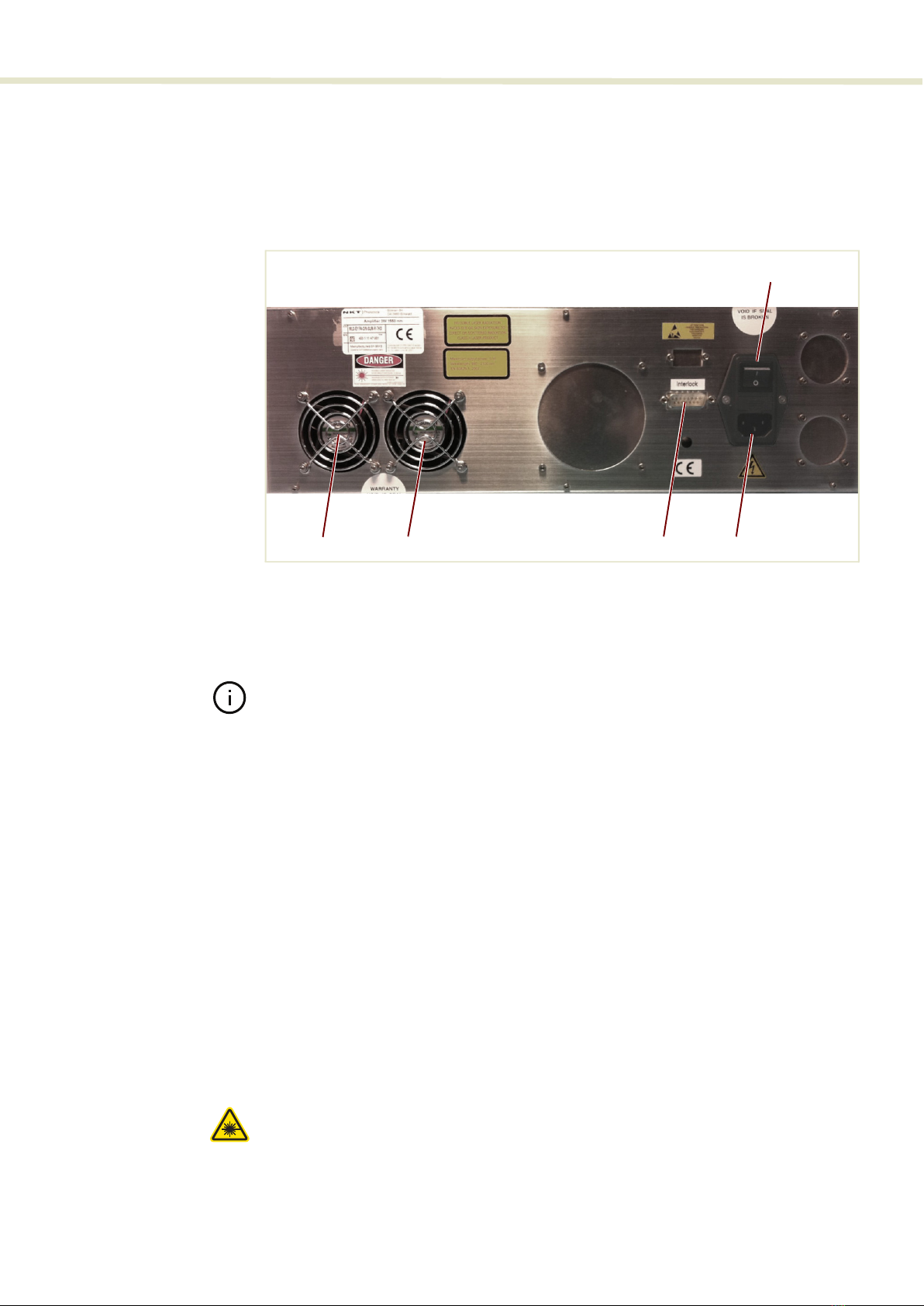
Rear panel Figure 3
shows the rear panel is made up of multiple connectors and a large cooling
fin array to maintain the BASIK modules at an optimum operational temperature.
The panel provides connectivity for control signals, safety interlock, accessories, and
AC mains.
Figure 3 BOOSTIK HP rear panel layout
Note:
The pin assignments of the Interlock are described in
“Connecting the BOOS-
TIK HP” on page 31
.
AC mains switch
Press ( I ) to turn on the amplifier and ( 0 ) to turn it off.
Cooling fans
The fans blow hot air out from the chassis, ensure there is adequate clearance for
proper airflow.
AC mains input
AC inlet - standard IEC C-14 mains inlet connector - see “Connecting power” on
page 32.
Interlock
Male DB-15 connector – connect to a safety interlock switch which is operated by the
access door to the laser operational area.
“Connecting the safety interlock” on
page 31
.
Warning: DO NOT BYPASS the interlock by jumping the pins on the connector.
Laser regulations require that the interlock is connected to a safety door switch.
When the door switch circuit is open the laser is immediately disabled.
1 AC mains ON/OFF switch 3 Interlock connectori
i. Interlock pin assignments – see Appendix Connecting the safety interlock
2 Cooling fans 4 AC mains input
5
34
1
2 2

Front and rear panels
16
Warning:
The Koheras BOOSTIK HP system has built-in safety relay and interlock
features to help ensure laser radiation is emitted only when desired and only when
predetermined conditions are met.
The Koheras BOOSTIK HP system has built-in safety relay and interlock features to
help ensure laser radiation is emitted only when desired and only when
predetermined conditions are met.
The remote interlock and remote stop features render the system inoperable when a
predefined condition occurs, such as the opening of a door. The internal safety relay
is analogous to a beam shutter. It interrupts drive current to the diode pump lasers,
and it is open each time the system is turned on. This means it will be impossible to
apply current to the diode pump lasers until you close the circuit and reset the front
panel key switch.

17
Optical output
Optical output
Optical output can be one of five types. The type used is dependent on the amplifier
power level, wavelength and on some models the output number. Refer to
Table 2
below for details.
Note: For dimensions of the Optical output types, refer to Figure 18 on page 38.
Table 2 Optical output types
Miscellaneous
Safety
Warning: The lasers output from the chassis is rated as class 4 laser and is there-
fore hazardous. Before turning on the BOOSTIK HP and connected seed laser,
ensure to read and understand all safety statements of the document:
Koheras ACOUSTIK Safety, Handling and Regulatory Information
A paper copy of this document is included with your laser. If you do not have access
it, you can download a copy from:
https://www.nktphotonics.com/lasers-fibers/support/product-manuals/
Optical output type
Wavelength
(nm)& fiber type
Output
power (W)
Fiber
length
(m)
Collimated
FC/APC
Collimator
only
Collimator
with Isolator
type 1
Collimator
with isolator
type 2
10xx PM 2 2
1030 PM 5 2
1050 PM 5 2
1064 PM 5 2
10xx PM 10 1.5
15 1
1550-1570 PM 2 2
5 2
10 1.5
15 1
1550-1570 SM 2 2
Multiport 1 i
i. Standard FC/APC connector (non-collimated)

Managing the amplifier
18
Managing the amplifier
Operations
interface
The amplifier is operated either from the front panel or through a Command Line
Interface accessible through the USB RS-232 connection on the front panel.
“Operating the BOOSTIK HP Amplifier” on page 21
includes information on how to
operate the amplifier with both interfaces.
Emission LEDs
The Emission Enable/Disable button on the front panel houses an Emission LED LED
as described in
Table 3
. The LED is located in the center of the button as shown in
Figure 2
.
Table 3 Emission LEDs
Note:
DO NOT OPERATE the BOOSTIK HP until you are familiar with the controls and
have taken all precautions necessary as described in the document: Koheras BOOS-
TIK HP Safety, Handling and Regulatory Information.
LED Name Condition Description
Emission ON Blue Laser emission is ON.
OFF Laser emission is OFF.

19
Chassis labels
Chassis labels
A Koheras BOOSTIK HP chassis has a number of labels on it that indicate hazards,
regulatory, or manufacturing information. The labels are located on the panels
described in
Table 4
.
Table 4 Module labels
Label Panel Description
Classification -
Emission
Hazards
Top Safety information stating the laser emission
hazards and the laser’s class rating.
Product
Information
Top Safety label showing the emission
specifications of the laser.
Laser Radiation
Warning
Front Safety information alert indicating this
area of the laser is near a source of
dangerous laser emissions.

Chassis labels
20
This manual suits for next models
1
Table of contents


