NKT Koheras BOOSTIK User manual

Koheras BOOSTIK
Compact Fiber Amplifier
User Guide
1
Package Contents
Confirm all items are included with your amplifier.
Description
.
Koheras BOOSTIK
Specification Sheet, Safety
notice and this guide
USB Stick with GUI Software
and Documentation
Warning:
The Koheras BOOSTIK amplifiers are rated as Class
3B and Class 4 laser devices. Before any operation is attempted,
ensure the notices within this manual and the hazard labels on the
product, are read, noted, and adhered to.
In addition, make sure to follow all safety recommendations listed
in the Koheras BOOSTIK Safety and Handling Information
document shipped with your amplifier. If in doubt, consult your
laser safety officer.
Warning:
Not installing a door interlock may expose persons to
harmful laser emissions. The responsible party must ensure that
staff is properly trained in the safe operation of a Class 4 laser.
Note:
DO NOT dispose of the packaging your amplifier was
shipped in. It is vital to keep it available for future shipping
requirements.
Reference documentation
The Koheras BOOSTIK is a module which is a component of a laser system. For further information regarding
Koheras modular system components refer to the following documentation
• Koheras ACOUSTIK User Manual V4
• Koheras BASIK User Manual V5
BEFORE OPERATING THIS DEVICE: READ and UNDERSTAND the information listed in the included document:
• Koheras BOOSTIK Laser Safety and Handling Information
The Koheras BOOSTIK is a compact fiber amplifier module for
low-noise, narrow-linewidth Koheras seed lasers. It operates in
the 1060-1075 nm or 1545-1565 nm wavelength range.
Depending on the variant, the amplifier is designed to extend
the output power of an associated seed laser to either 200
mW or 2 W output power. The amplifier achieves this while
preserving the seed laser’s ultra-low noise and narrow
linewidth optical output. BOOSTIK amplifier modules are
components of a laser system designed to be inserted into two
slots of a Koheras ACOUSTIK cabinet and coupled with
Koheras BASIK seed lasers. For slot installation, the module
includes a slot alignment pin hole to ensure the electrical
connector mates correctly. Additionally, a front panel (not
shown) can be fastened to the cabinet front face. The module
can also be implemented as a component in custom laser
systems. For these applications, NKT Photonics’ SDK is
available to integrate the module with the system control
platform.
Status LEDs
Optical output
Optical input
Main electrical interface
Handle
Handle
Alignment
pin hole
M4 M4
FRONT PANEL REAR PANEL
Koheras BOOSTIK User Guide Revision 1.3 08-2020 W-10456
Koheras BOOSTIK
User Guide
2
Standard Optical specifications
Status LEDs
Labels
Koheras BOOSTIK modules include multiple labels that indicate hazards, compliances, or manufacturing
information. The table below lists the labels, their panel location and description. Before operating the amplifier
module, ensure that you understand all safety labels and their content.
Specification
Mode of operation Continuous wave - inherently single frequency
Output power 2.0 W
Wavelength range 1060-1075 nm or 1545-1565 nm
Output fiber PM980i
i. 1060-1075 nm amplifier
PM1550 or SMF28ii
ii. 1545-1565 nm amplifier
Input power 1 – 50 mW
Input and output optical termination FC/APCiii
iii. For other connector solutions contact NKT Photonics
LED Name Condition Description
Power ON Green DC Voltage at the DC power input pins is OK.
ON Red DC voltage at the DC power input pins is too low.
Flashing Amber The module is transmitting data.
OFF No DC power at the module power input pins.
Emission ON Red Laser amplifier emission is ON.
OFF Laser amplifier emission is OFF.
Status ON Green Output power OK
ON Amber Module ready
Interlock ON Green The interlock status is OK – the door circuit is closed and energized.
ON Red The interlock status is Not OK – the door circuit is open or not energized.
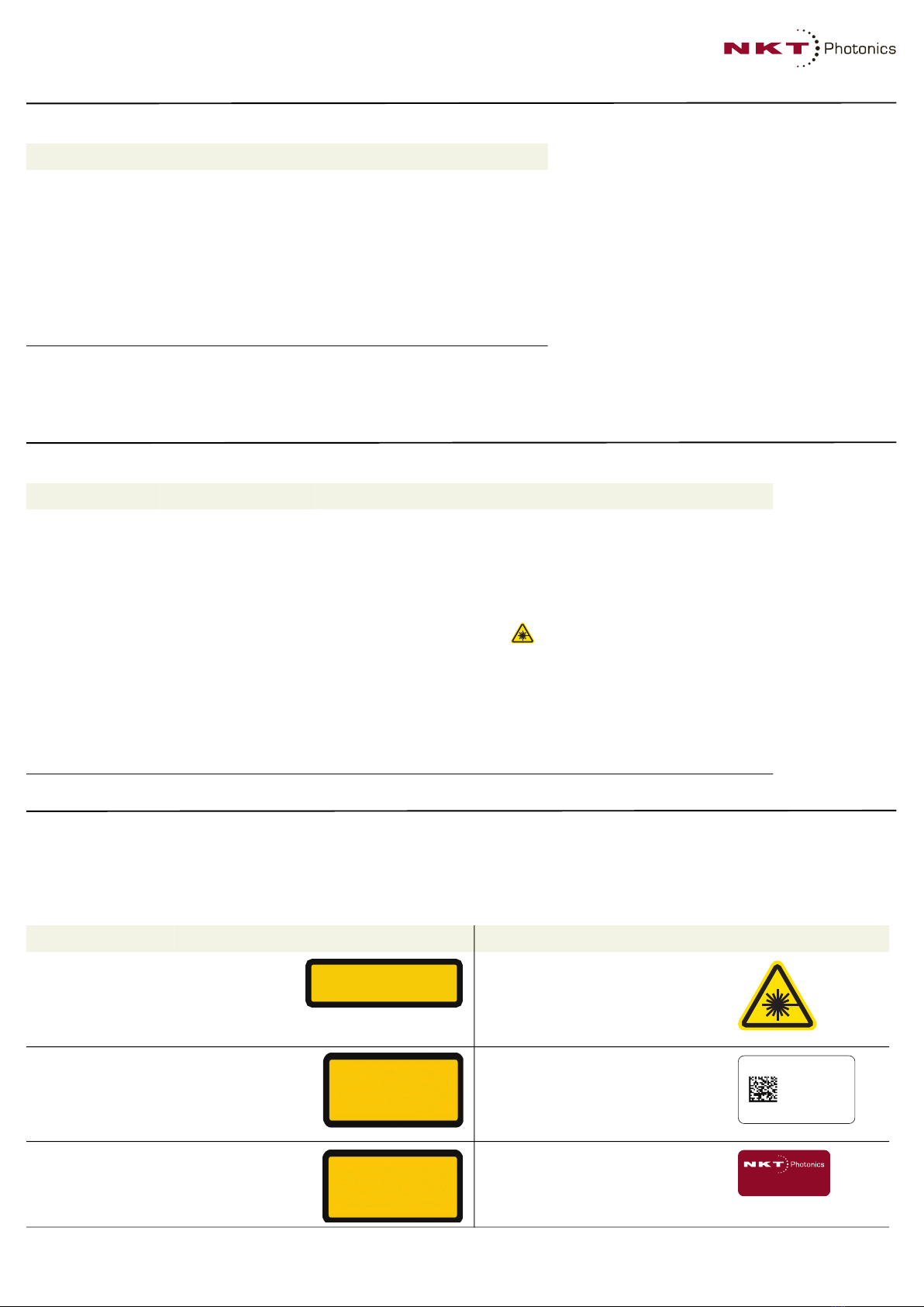
Label Panel Description Label Panel Description
Laser
component
designation
Top Statement
indicating the
device is a
component of a
laser system.
Laser
Radiation
Warning
Top Safety information
alert indicating this
area of the laser is
near a source of
dangerous laser
emissions.
Classification
emission
hazards
Top Safety information
stating the laser
emission hazards and
the amplifier’s laser
class rating.
Manufac-
turing
Side Manufacturing
information
including address,
part and serial
number, and date
manufactured.
Product
information
Top Safety label showing
the emission
specifications the
amplifier is capable of.
Warranty Top The module is
sealed with this
label. It is prohibited
to remove the
chassis cover.
DESIGNATED FOR USE SOLELY AS A COMPONENT,
AND DOES NOT COMPLY WITH IEC 60825-1 OR
21 CFR 1040.10 AS A COMPLETE LASER PRODUCT
DANGER - INVISIBLE LASER RADIATION
AVOID EYE OR SKIN EXPOSURE TO
DIRECT OR SCATTERED RADIATION
CLASS 4 LASER COMPONENT
NKT Photonics
K592-CR
K009862
Manufactured: 12-2019
MAXIMUM OUTPUT POWER: 5 W
WAVELENGTH: 900 - 2100 nm
EN60825-1:2014
WARRANTY VOID IF SEAL
IS BROKEN OR REMOVED
Koheras BOOSTIK
User Guide
3
Main Electrical Interface
Pin # Signal Description
A1 Module OK Low: module enable low OR module power low
High: module power high
A2 RS485- Negative/inverted RS485 differential data signal
A3 Interlock loop+ Positive connection of interlock loop. Should be connected to Interlock loop- (pin no. 4) to enable
emission from the system.
A4 Interlock loop- Negative connection of interlock loop. Should be connected to Interlock loop+ (pin no. 3) to
enable emission from the system.
A9 N/C
A10 N/C
B1 Service NKTP Technical Support
B2 Service NKTP Technical Support
B3 Service NKTP Technical Support
B4 N/C
B9 AGND Analog ground for amplitude and wavelength modulation signals.
B10 AGND Analog ground for amplitude and wavelength modulation signals.
C1 Emission Collector output with internal 240 Ω resistor in series. The output is high when the amplifier
emission is ON. An LED anode can be connected directly to this pin and the Cathode to GND to
indicate emission externally.
C2 RS485 Positive/non-inverted RS485 differential data signal
C3 Enable Logic input that permits emission when a high (5V) i is applied. During emission if Enable is set
low, emission is shut off.
C4 Enable logic input Logic input that permits emission when a high is applied. If during emission the input is set low,
emission is shut off. This control input is for personal safety and is designed with redundancy
within the module.
C9 N/C
C10 N/C
A5, A6,
B5, B6,
C5, C6
GND 0 volt / ground
A7, A8,
B7, B8,
C7, C8
12V 12 volt supply voltage for the module.
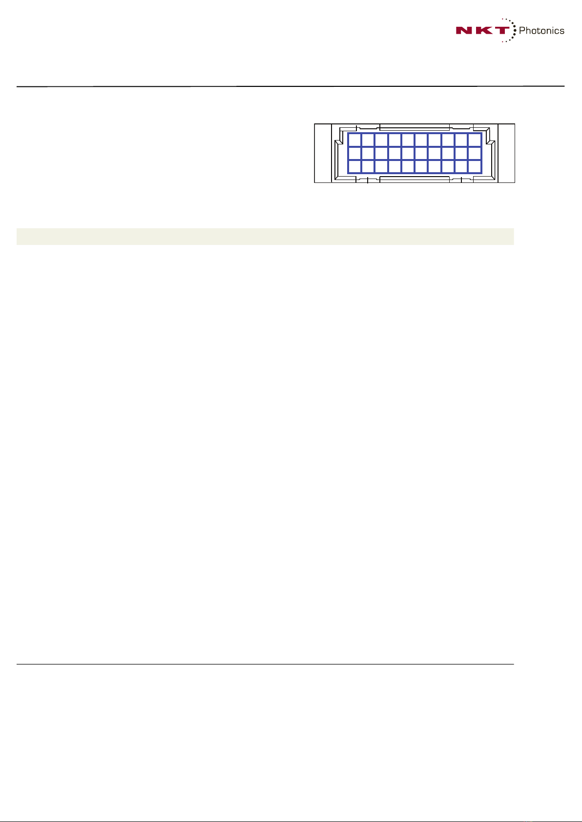
The main electrical interface is a 30-pin male C/3 connector
located on the rear panel of the module. The pins are arranged as
shown in the figure on the right with the pin assignments listed
below.
C
B
A
10 987654321
30 pin DIN41612 male C/3 type
Koheras BOOSTIK
User Guide
4
Custom stand-alone installation
For simple custom systems, the amplifier module must be placed on a
level and stable surface. The module can be bolted for example, to a
table using a custom mounting bracket (not included) attached to the
side of the module.
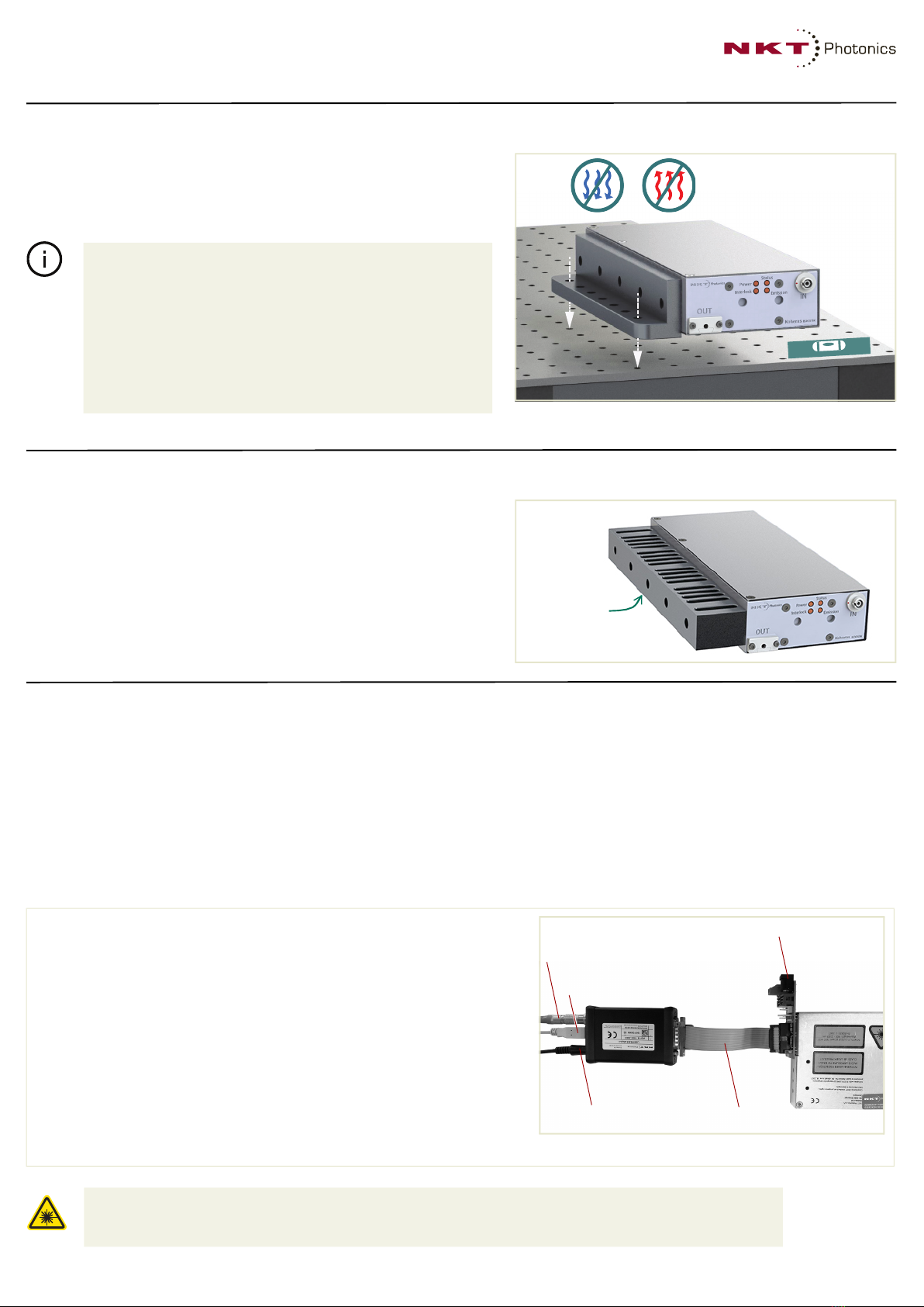
Cooling
The amplifier module generates substantial heat during operation. For
proper operation, you must ensure that the heat is dissipated by
providing an efficient thermal path from either the rear panel or the
side panel as illustrated. (Cooling blocks or heat sinks are not included.)
Connect the module to a CONTROL PC
The amplifier module is designed as a component in a laser system that includes safety and communication
functionality. The module can be operated using NKT Photonics CONTROL application installed on a PC. To
establish communication between a CONTROL PC and the amplifier, first make the following connections to the
appropriate main electrical interface:
• 12 VDC power and ground
• A door switch safety interlock circuit that complies with applicable safety regulations.
• An RS-485 data connection between a PC and the amplifier.
Note:
Follow these installation rules:
• Allow for proper ventilation and cable access.
• Do not store or place anything on the top panel of the amplifier.
• Ensure the ambient operating temperature and humidity is
stable as stated in the “Amplifier Specifications”. Avoid placing
the amplifier near sources that could cause temperature
fluctuations.
• The surface the amplifier is placed on, must be free of vibration
or mechanical shocks.
Optional RS-485 adapter kit
For system integration and testing, the amplifier module can be provided with an
optional kit that provides the necessary power, interlock and communications to
operate a stand-alone module. To use the kit, follow the steps below and refer to
the adapter description “RS-485 Adapter” on page 8:
a. Connect the BOOSTIK interface board to the main interface 30 pin C/3
connector on the rear panel of the module.
b. Using the IDC 16 pin to DB-15 ribbon cable, connect the NKT Photonics RS-485
adapter to the 16 pin main interface connector on the BASIK interface board.
c. Connect the RS-485 adapter to your PC using the USB-A to USB-B cable.
d. Connect a door safety switch circuit using the two-pin LEMO connector to the
interlock port of the RS-485 connector.
e. To power on the module, connect the power supply to the RS-485 adapter
power jack and AC mains.
Warning:
When using the adapter kit, DO NOT CONNECT a laser seed source and ONLY use the adapter kit for
temporary test purposes. Connecting the BOOSTIK to a laser seed source along with an RS-485 adapter is UNSAFE
and contravenes IEC standard 60825-1 Safety of Laser Products.
M6 xM6 x ?boltbolt
M6 xM6 x ?boltbolt
Cooling block
attached to
side panel
Ribbon cable
USB to PC
12 VDC input
Interlock
BOOSTIK interface board

Koheras BOOSTIK
User Guide
5
Start and connect CONTROL
1 Start the NKT Photonics CONTROL application on the connected
PC.
2 Click the Connect button.
3 Wait for CONTROL to scan all available ports.
4 When CONTROL connects to the module, the Control Panel and
Status Panel will appear.
Set the module amplifier to power or current mode
1 In the status panel, click on the settings gear icon and from the
drop down menu, select Power/current mode.
2 In the Settings panel, click on the Mode drop down menu, and
select Power or Current.
3 Selecting:
• Power mode configures the amplifier booster output power to be
held constant at the set level.
• Current mode configures the amplifier booster pump current is held
constant at the set level.
4 Click the icon to return to the main Control panel view.
Note:
The CONTROL installer can be downloaded from the
following URL:
https://www.nktphotonics.com/lasers-fibers/support/software-
drivers/
Click the
Connect
button
Status panelControl panel
Click Standby:
1: Standby indicator Blinks &
Listen indicator stays ON
2: Standby indicator ON Amber
& Listen indicator extinguished
3. Laser is now warmed up.
Mode drop
down menu
Koheras BOOSTIK
User Guide
6
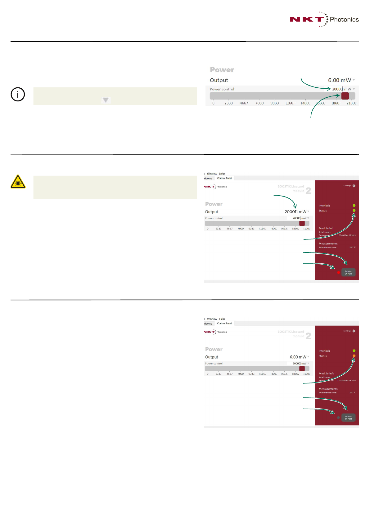
Set the output power level
1 If Power mode is selected, set the output power in mW or dBm by
moving the slide control (click-hold and drag it).
2 Alternatively, enter the level directly in the power level text box.
Enable emission
1 Check to ensure all safety measures are in place and the interlock
indicator is ON Green.
2 To enable emission, click the Emission button once.
3 The indicator next to the button turns ON Red when emissions are
enabled.
4 If emissions are enabled correctly. the Status indicator changes to
ON Green.
5 The system measured output level is shown on the right in the
Control panel above the power level slider.
Disable emission
1 To disable emission, click the Emission button once.
2 The indicator next to the button turns OFF (grey) when emissions
are disabled.
3 When emissions are disabled. the Status indicator changes back to
ON Amber.
Note:
The power unit can be changed between mW and dBM by
clicking on the down arrow next to the power text input box.
Warning:
When emission is enabled. dangerous emissions are
present. Take all possible safety precautions beforehand and
during when operating the amplifier module.
Slide the red button to the desired power
(shown set to 200 mW
Power level text input box
Emission button
Emission indicator
Status indicator
Measured power
Emission button
Emission indicator
Status indicator
Koheras BOOSTIK
User Guide
7
Amplifier Specifications
Support
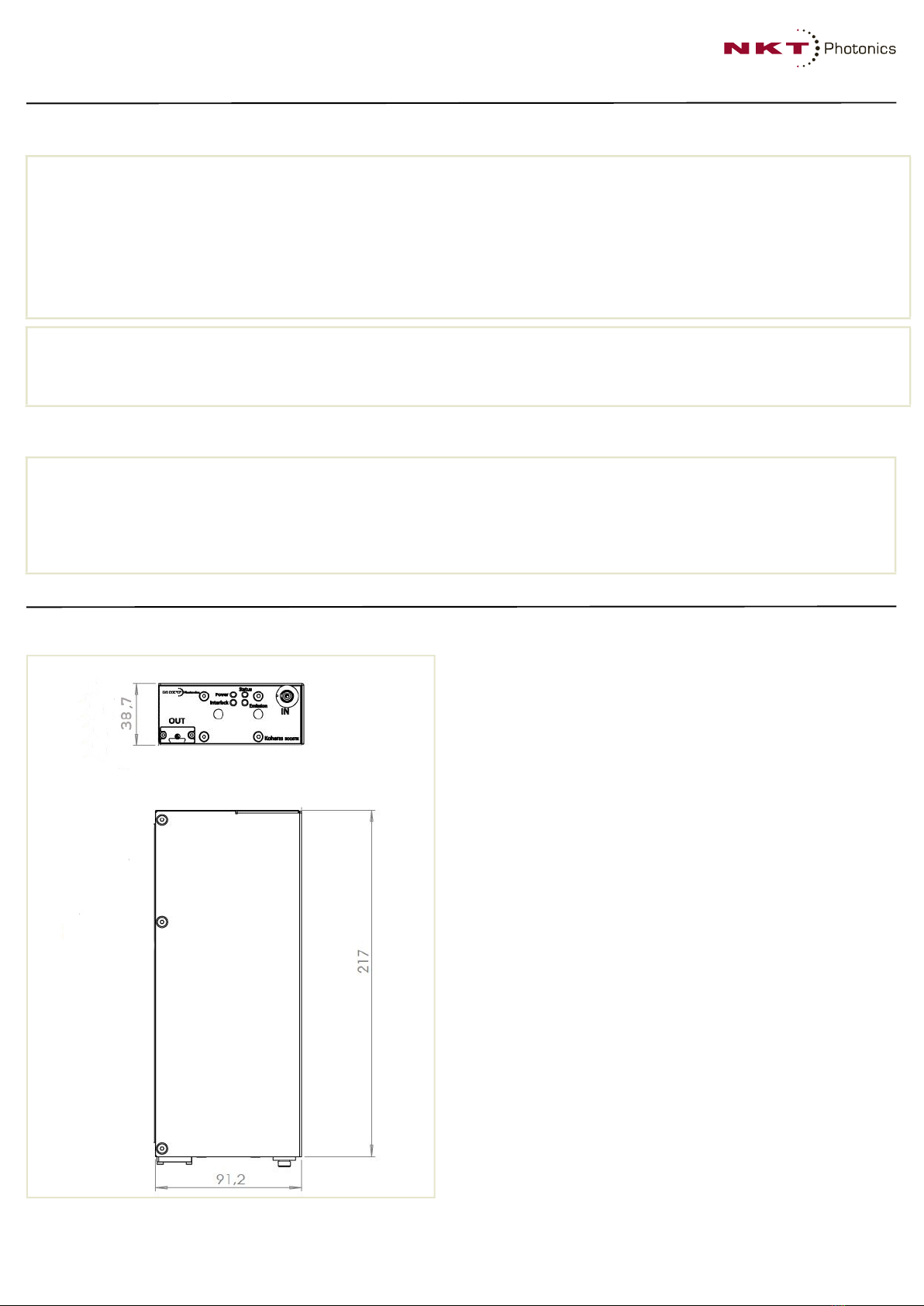
Mechanical Dimensions
Chassis Compliances
Size (W x D x H) 92 x 220 x 39 mm Safety N/A
Weight < 1 kg Regulatory N/A
Operating Temperature Range 15°C to 55°C (internal case/module temperature)
Storage Temperature -20°C to 60°C
Ambient Operating Humidity 20 to 80% (relative, non-condensing)
DC Input Power
DC Input Power 12 V, 2.5 A
Maximum Power Consumption 30 W
Web http://www.nktphotonics.com/ (click on support)
Email s[email protected]
Shipping Address NKT Photonics A/S
Blokken 84
3460 Birkerød
Denmark

Koheras BOOSTIK
User Guide
8
RS-485 Adapteri
An RS-485 adapter kit can be provided separately. The adapter functions include:
• Input for DC power
• USB to RS-485 communication ports
• Interlock connections and defeater (jumper)
• Status LEDs
The adapter connects and converts the module’s RS-485 communication signals to USB. The USB level signals
can then be connected to a CONTROL PC or a custom control platform using the SDK. The adapter connects to
the module using a 16 pin ribbon cable with a male DB-15 connector. For USB connectivity the adapter is
equipped with a B-type USB port that can typically connect to a PC using a standard Type A to Type B USB cable.
The adapter also provides a two pole power input socket to connect with an external power supply. The
connected DC supply powers the adapter and also provides power to the module through the DB-15 connector
and ribbon cable.
To connect the module’s interlock pins to a door switch, the adapter is equipped with a standard 2 pin LEMO
connector. The LEMO connector is connected internally to the adapter’s DB-15 connector and the interlock pins
on the module’s main interface connector through the ribbon cable.
i. If not included, A connector kit with the adapter is available by contacting NKT Photonics support - see “Support” on page 7
Warning:
When using the adapter kit, DO NOT CONNECT a laser seed source and ONLY use the adapter kit for
temporary test purposes. Connecting the BOOSTIK to a laser seed source along with an RS-485 adapter is UNSAFE
and contravenes IEC standard 60825-1 Safety of Laser Products.
1. 2-pin LEMO interlock connector 4 12 VDC power input
2 USB type B connector 5 Interlock defeater (jumper)
3 Status LEDs – see descriptions below 6 DB-15 module interface
Status LED Condition Description Status LED Condition Description
Power OFF No power connected Emission OFF No emission
ON Green 12 VDC power connected ON RED Emission enabled
TX/RX Flashing RED Adapter receives USB data
(from PC)
Flashing GREEN Adapter receives RS-485 data
(from laser)
1 2 3 4 5
6
External Module
Connections Connection
Table of contents


