4
Configure Stage1 / Input1 Operating Mode
Normal Mode—When Stage1 and/or Input1 is configured for Normal operation the AMS-500
will immediately apply the pressure selected with the Stage1 Programming switches when Input1 be-
comes active. If Stage2 / Input2 is active the Stage1 setting will override the Stage2 setting.
Example—Stage1 set at 12psi, Stage2 psi set at 8psi. When Stage1 is activated the AMS-500 would ap-
ply 12psi to the system whether Stage2 is active or not. The Stage2 Green LED will blink four times at
power up to indicate this mode is active.
Launch Mode—When Stage1 / Input1 is configured for Launch Mode operation the AMS-500
will ignore the Stage2 / Input2 activation until Input1 is released. This allows a Launch psi to be set for
Stage1 and then Stage2 can be used to Ramp the target pressure up / down after the launch. Typical op-
eration would be to connect Input1 to a clutch and/or trans brake switch and Input2 to a wide open throt-
tle switch. The Stage1 Green LED will blink four times at power up to indicate this mode is active.
Dual Stage Mode—When Stage1 / Input1 is configured for Dual Stage Mode operation the
AMS-500 allows both Inputs/Stages to be combined. Whichever Input is activated first becomes the
First Stage, this Input may remain ON or OFF while the second Input is Activated. The Stage1&2 Green
LED’s will blink four times at power up to indicate this mode is active.
Switching between modes of operation
1—Set Stage1 and Stage2 programming switches to 0. Set Stage2 Ramp Rate select
switch to 1.
2—Turn AMS-500 on, the Stage1 Green LED will blink once per second for 10 sec-
onds. To change Stage1 operating mode you must wait 10 seconds with the Red LED blinking.
3—After 10 seconds the AMS-500 will automatically switch Stage1 operating modes.
The new operating mode selected will be indicated by flashing the either the Stage or Stage2
Green LED. Use the guide below to determine the current Stage1 Mode selected.
Normal Mode—Stage2 Green LED will blink 5 times per second.
Launch Mode—Stage1 Green LED will blink 5 times per second.
Dual Stage Mode—Stage1&2 Green LED’s will blink 5 times per second.
4—Turn power off, set switches for desired target psi and ramp rate for Stage2.
5—Turn power back on and AMS-500 is ready to operate in selected mode.
IMPORTANT—At least one Stage Programming switch must be non-zero for operation.
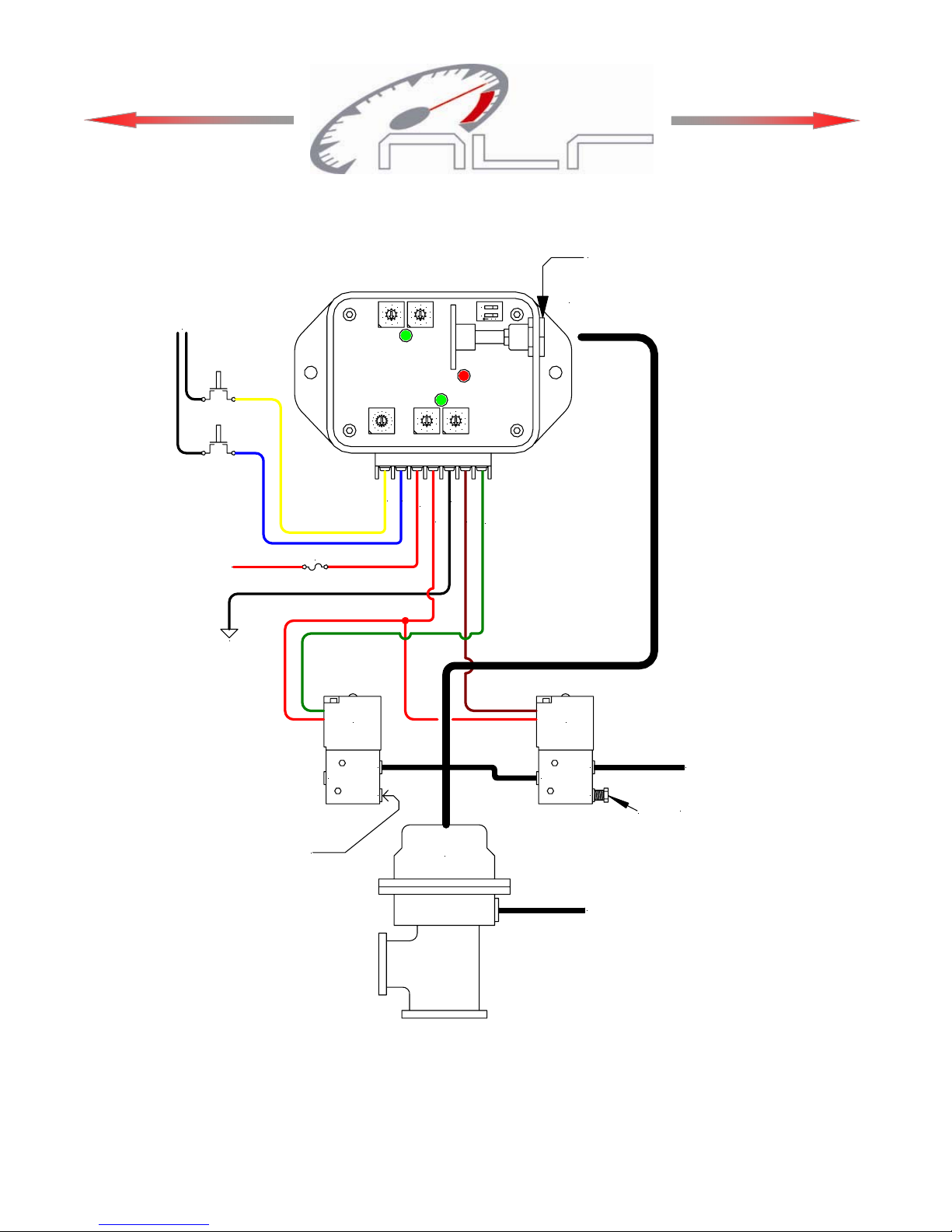
IMPORTANT—The AMS-500 controls the pressure on the Waste Gate so the actual
boost level obtained is a combination of the Waste Gate Spring pressure and pressure
applied by the controller www.nlrsystems.com or
Phone 334-741-7100