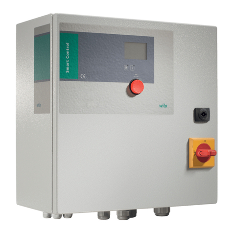
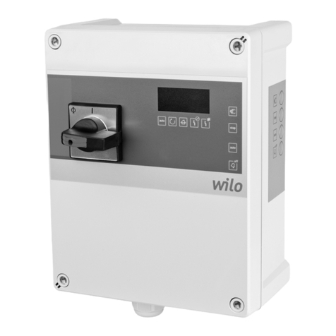
Wilo Control MS-L User manual

Pioneering for You
·
Wilo-Control MS-L
2552612 • Ed.02/2022-05
en Installation and operating instructions

Control MS-L
https://qr.wilo.com/1393

Fig. 3: Control MS-L1...
L1
L1L2L3N
L1 N
1 2 3 4
1 2 3 4
L2 L3 PE WSK
M
3~400V 50/60Hz
3~
M
L N PE
N
WSK
1~230V 50/60Hz
1~
L N
ON / OFF ON /
U V W
L N
min. 12 VDC, 10 mA
max. 250 VAC, 1 A
120
60
0
Seconds
ON
100 K
DIP
12345678
PE 1 2 37 8 9 4 5 6
GLWSK HW
T1
1 3 5 13 A1
2 4 6 14 A2
T2 T3
L1 L2
1/L1 3/L2 5/L3 N
2/T1 4/T2 6T3 N
L3 NO
1
15
6
8
2
34
73
7
7
SSM
A
B
D F
C

Fig. 3: Control MS-L1...-O
L1L2L3N
L1 N
PE WSK
M
3~400V 50/60Hz
3~
M
PE WSK
1~230V 50/60Hz
1~
L N
ON / OFF ON /
U V W
L N
1 2 3 4
1 2 3 4
120
60
0
Seconds
ON
100 K
DIP
12345678
PE 1 2 37 8 9 4 5 6
GLWSK HW
T1
1 3 5 13 A1
2 4 6 14 A2
T2 T3
L1 L2 L3 NO
5
6
8
2
34
73
7
7
SSM
min. 12 VDC, 10 mA
max. 250 VAC, 1 A
A
B
D F
C

Fig. 3: Control MS-L1...-LS
WSK
M
3~
WSK
M
1~
L N
ON / OFF
NW21/NW22
U
bk
bn
V W
N L
L1 L2 L3 PE
3~400V 50/60Hz
L1
(L)
L2
(N)
PE
1~230V 50/60Hz
30
15
0
Seconds
ON
100 K
DIP
1234567
PE 1 2 57 8 9 6
WSK
T1
1 3 5 13 A1
2 4 6 14 A2
T2 T3
L1 L2 L3 NO
5
6
8
ON
1 2 3
10
2
3 34
Sensor
+ ln
SSM
min. 12 VDC, 10 mA
max. 250 VAC, 1 A
G
C

Fig. 3: Control MS-L2...
WSK
M
3~
WSK
M
1~
ON / OFF
P1 P2
P1 P2
P1 P2
ON / ON
U V W U V W
L N L N
120
60
0
Seconds
ON
100 K
DIP
1234567
SSM Alarm
GL
WSK
-P2
WSK
-P1 SL
10161514131211 987654321
HW
T1
1 3 5 13 A1
2 4 6 14 A2
T2 T3
L1 L2 L3 NO
L1 L2 L3 N
WSK
M
3~
WSK
M
1~
T1
1 3 5 13 A1
2 4 6 14 A2
T2 T3
L1 L2 L3 NO
ON DIP
1234567
PE
L1 L2 L3 PE
3~400V 50/60Hz
NL1 L2 L3 N
L1 N
1 2 3 4
1 2 3 4
L N PE
1~230V 50/60Hz
1/L1 3/L2 5/L3 N
2/T1 4/T2 6/T3 N
L N
1
1
9
5
8
2 2
7
7
7
4
6
33
min. 12 VDC, 10 mA
max. 250 VAC, 1 A
A
B
D E F
C

Fig. 3: Control MS-L2...-O
WSK
M
3~
WSK
M
1~ ON / OFF
P1 P2
P1 P2
P1 P2
ON / ON
U V W U V W
L N L N
120
60
0
Seconds
ON
100 K
DIP
1234567
SSM Alarm
GL
WSK
-P2
WSK
-P1 SL
10161514131211 987654321
HW
T1
1 3 5 13 A1
2 4 6 14 A2
T2 T3
L1 L2 L3 NO
L1 L2 L3 N
WSK
M
3~
WSK
M
1~
T1
1 3 5 13 A1
2 4 6 14 A2
T2 T3
L1 L2 L3 NO
ON DIP
1234567
PE
PE
3~400V 50/60Hz
L1 L2 L3 N
L1 N
1 2 3 4
1 2 3 4
PE
1~230V 50/60Hz
L N
9
5
8
2 2
7
7
7
4
6
33
min. 12 VDC, 10 mA
max. 250 VAC, 1 A
A
B
D E F
C

Fig. 3: Control MS-L2...-LS
P1 P2
L1 L2 L3 PE
WSK
M
3~400V 50/60Hz
3~
L1
(L)
L2
(N)
PE
WSK
M
1~230V 50/60Hz
1~
L N
P1 P2
P1 P2
U
bk
bn
V W
30
15
0
Seconds
ON
100 K
DIP
1234567
SSM Alarm
WSK
-P2
Sensor
+ ln
WSK
-P1
161514131211 1094321
T1
1 3 5 13 A1
2 4 6 14 A2
T2 T3
L1 L2 L3 NO
WSK
M
3~
WSK
M
1~
U V W
N L N L
T1
1 3 5 13 A1
2 4 6 14 A2
T2 T3
L1 L2 L3 NO
ON DIP
1234567
PE
L1 L2 L3 N
9
5
8
2 2
4
6
3 3
ON
1 2 3
10
ON / OFF
NW21/NW22
min. 12 VDC, 10 mA
max. 250 VAC, 1 A
G
C

en
Installation and operating instructions • Wilo-Control MS-L • Ed.02/2022-05 9
Table of contents
1 General information .................................................................10
1.1 About these instructions ...................................................10
1.2 Digital instructions..............................................................10
1.3 Copyright .............................................................................10
1.4 Subject to change ...............................................................10
1.5 Exclusion from warranty and liability ...............................10
2 Safety.........................................................................................10
2.1 Identification of safety instructions.................................10
2.2 Personnel qualifications.....................................................11
2.3 Electrical work .....................................................................12
2.4 Monitoring devices .............................................................12
2.5 Installing/dismantling.........................................................12
2.6 During operation .................................................................12
2.7 Maintenance tasks..............................................................13
2.8 Operator responsibilities....................................................13
3 Application/use.........................................................................13
3.1 Intended use ........................................................................13
3.2 Improper use........................................................................13
4 Product description..................................................................13
4.1 Structure ..............................................................................13
4.2 How it works ........................................................................14
4.3 Technical data .....................................................................14
4.4 Inputs and outputs .............................................................15
4.5 Functions..............................................................................15
4.6 Type key ...............................................................................15
4.7 Operation on electronic start-up controllers .................16
4.8 Installation in potentially explosive atmospheres..........16
4.9 Scope of delivery.................................................................16
4.10 Accessories ..........................................................................16
5 Transportation and storage.....................................................16
5.1 Delivery.................................................................................16
5.2 Transport..............................................................................16
5.3 Storage .................................................................................16
6 Installation ................................................................................17
6.1 Personnel qualifications.....................................................17
6.2 Installation types.................................................................17
6.3 Operator responsibilities....................................................17
6.4 Installation ...........................................................................17
6.5 Electrical connection ..........................................................18
6.6 Functions..............................................................................25
7 Operation ..................................................................................26
7.1 Operating elements ............................................................26
7.2 How it works ........................................................................28
8 Commissioning .........................................................................28
8.1 Operator responsibilities....................................................28
8.2 Commissioning in explosive atmospheres ......................29
8.3 Connection of signal transmitters within potentially ex-
plosive atmospheres...........................................................29
8.4 Activating the device .........................................................29
8.5 Installing the rechargeable battery ..................................30
8.6 Check the direction of rotation of the connected pumps
...............................................................................................30
8.7 Start automatic mode..........................................................31
8.8 During operation ..................................................................31
9 Shut-down.................................................................................31
9.1 Personnel qualifications ......................................................31
9.2 Operator responsibilities.....................................................31
9.3 Shut-down............................................................................31
9.4 Removal.................................................................................32
10 Maintenance and repair............................................................32
10.1 Maintenance intervals .........................................................32
10.2 Maintenance tasks ...............................................................32
11 Faults, causes and remedies ....................................................33
11.1 Operator responsibilities.....................................................33
11.2 Fault indication.....................................................................33
11.3 Fault acknowledgement .....................................................33
11.4 Error messages .....................................................................33
11.5 Fault memory........................................................................33
11.6 Further steps for troubleshooting .....................................34
12 Disposal......................................................................................34
12.1 Rechargeable battery ..........................................................34
12.2 Information on the collection of used electrical and elec-
tronic products .....................................................................34
13 Appendix....................................................................................34
13.1 System impedances.............................................................34
en
10 Installation and operating instructions • Wilo-Control MS-L • Ed.02/2022-05
1 General information
1.1 About these instructions These instructions form part of the product. Compliance with the instructions is essential
for correct handling and use:
•Read the instructions carefully before all activities.
•Keep the instructions in an accessible place at all times.
•Observe all product specifications.
•Observe the markings on the product.
The language of the original operating instructions is German. All other languages of these
instructions are translations of the original operating instructions.
1.2 Digital instructions The digital version of the instructions is available on the following product page:
https://qr.wilo.com/1393
1.3 Copyright WILO SE © 2022
The reproduction, distribution and utilization of this document as well as the communica-
tion of its contents to others without express authorization is prohibited. Offenders will be
held liable for the payment of damages. All rights reserved.
1.4 Subject to change Wilo shall reserve the right to change the listed data without notice and shall not be liable
for technical inaccuracies and/or omissions. The illustrations used may differ from the ori-
ginal and are intended as an example representation of the device.
1.5 Exclusion from warranty and liabil-
ity
Wilo shall specifically not assume any warranty or liability in the following cases:
•Inadequate configuration due to inadequate or incorrect instructions by the operator or
the client
•Non-compliance with these instructions
•Improper use
•Incorrect storage or transport
•Incorrect installation or dismantling
•Insufficient maintenance
•Unauthorised repairs
•Inadequate construction site
•Chemical, electrical or electrochemical influences
•Wear
2 Safety This chapter contains basic information for the individual phases
of the life cycle. Failure to observe this information carries the
following risks:
•Risk of personal injury from electrical, electromagnetic or
mechanical influences
•Environmental damage from discharge of hazardous sub-
stances
•Damage to property
•Failure of important functions
Failure to observe the information contained herein will result in
the loss of claims for damages.
The instructions and safety instructions in the other chapters
must also be observed!
2.1 Identification of safety
instructions
These installation and operating instructions set out safety in-
structions for preventing personal injury and damage to property,
which are displayed in different ways:
•Safety instructions relating to personal injury start with a signal
word and are preceded by a corresponding symbol.

en
Installation and operating instructions • Wilo-Control MS-L • Ed.02/2022-05 11
DANGER
Type and source of the danger!
Consequences of the danger and instructions for avoidance.
•Safety instructions relating to property damage start with a
signal word and are displayed without a symbol.
CAUTION
Type and source of the danger!
Consequences or information.
Signal words
•Danger!
Failure to observe safety instructions will result in serious injury
or death!
•Warning!
Failure to follow instructions can lead to (serious) injury!
•Caution!
Failure to follow instructions can lead to property damage and
possible total loss.
•Notice!
Useful information on handling the product
Markups
✓Prerequisite
1. Work step/list
⇒Notice/instructions
▶Result
Symbols
These instructions use the following symbols:
Danger of electric voltage
Danger – explosive atmosphere
Useful information
2.2 Personnel qualifications Personnel must:
•Be instructed about locally applicable regulations governing ac-
cident prevention.
•Have read and understood the installation and operating in-
structions.
Personnel must have the following qualifications:
•Electrical work: A qualified electrician must carry out the elec-
trical work.

en
12 Installation and operating instructions • Wilo-Control MS-L • Ed.02/2022-05
•Installation/dismantling: The technician must be trained in the
use of the necessary tools and fixation materials for the relev-
ant construction site.
•Operation/control: Operating personnel must be instructed in
the functioning of the complete system.
Definition of “qualified electrician”
A qualified electrician is a person with appropriate technical edu-
cation, knowledge and experience who can identify and prevent
electrical hazards.
2.3 Electrical work •Electrical work must be carried out by a qualified electrician.
•Before commencing work, disconnect the product from the
mains and safeguard it from being switched on again.
•Observe applicable local regulations when connecting to the
mains power supply.
•Adhere to the requirements of the local energy supply com-
pany.
•Earth the product.
•Observe technical information.
•Replace a defective connection cable immediately.
2.4 Monitoring devices Circuit breaker
The size and switching characteristics of the circuit breakers must
conform to the rated current of the connected consumer. Ob-
serve local regulations.
2.5 Installing/dismantling •Locally applicable laws and regulations on work safety and ac-
cident prevention must be complied with.
•Disconnect the product from the mains and secure it against
being switched on again.
•Suitable fixation material must be used for the existing bearing
surface.
•The product is not watertight. Select an appropriate installation
site!
•Do not deform the housing during installation. Seals could leak
and affect the stated IPprotection class.
•The product may not be installed in potentially explosive areas.
2.6 During operation •The product is not watertight. Comply with protection class
IP54.
•Ambient temperature: -30 … +60°C.
•Maximum humidity: 50%, non-condensing.
•Do not open the switchgear.
•The user must notify the person in charge of every fault or ir-
regularity immediately.
•In case of damage to the product or connection cable, switch
off the product immediately.

en
Installation and operating instructions • Wilo-Control MS-L • Ed.02/2022-05 13
2.7 Maintenance tasks •Do not use any aggressive cleaners or scouring agents or fluids.
•The product is not watertight. Do not submerse the product in
fluids.
•Only carry out maintenance tasks mentioned in these installa-
tion and operating instructions.
•Only original parts from the manufacturer may be used for
maintenance and repairs. Use of parts other than the original
parts releases the manufacturer from any liability.
2.8 Operator responsibilities •Provide installation and operating instructions in a language
which the personnel can understand.
•Make sure that the personnel has had the corresponding train-
ing for the specified work.
•Safety and information signs mounted on the device must al-
ways be legible.
•Train the personnel on how the system operates.
•Eliminate risk from electrical current.
•To ensure safe working practice, define personnel responsibilit-
ies.
Children and persons younger than 16years or with reduced
physical, sensory or mental capacities or limited experience are
prohibited from handling the product! A technician must super-
vise persons younger than 18years!
3 Application/use
3.1 Intended use The switchgear is designed for level-dependent control of up to twopumps.
Intended use includes compliance with this manual. Any other use is regarded as non-com-
pliant with intended use.
3.2 Improper use •Installation in potentially explosive atmospheres
•Overflow of the switchgear
4 Product description
4.1 Structure
1
2
3
Fig.1: Control MS-L 1
1 Main switch
2 LED indicators
3 Control panel with buttons
Microcontroller-controlled switchgear for control of one or two pumps. Separate main switch
for directly switching the switchgear on and off. NOTICE!The MS-L...-LS and MS-L...-O ver-
sions do not have a main switch!

en
14 Installation and operating instructions • Wilo-Control MS-L • Ed.02/2022-05
1
2
3
Fig.2: Control MS-L 2
The current operating states (operation and fault) are visually indicated via LEDs on the front
side. Faults are also indicated audibly via an integrated buzzer. The last error is stored in the
fault memory.
LED indicators MS-L 1... MS-L 2...
Automatic mode • •
Pump operation • •
High water • •
Overload fault • •
Winding fault • •
Service interval indicator − •
Monitoring of certain operating parameters − •*
Key
− = not available, • = available
* Only “LS” version
Operation is via four or five buttons on the side-mounted control panel:
•Automatic mode
•Manual mode (for each pump)
•Stop (all pumps off)
•Buzzer off/reset
4.2 How it works The pumps are automatically switched on and off depending on the fill level:
•Control MS-L…/MS-L…-O:
–The level is detected via a two-position control with a float switch for each pump.
–The high water level is detected by a separate float switch.
•Control MS-L…-LS:
–The level is detected continuously via a rod float sensor (4…20mA signal).
–The high water level is detected by a separate switching point.
A follow-up time can be set for deactivation. When the high water level is reached, there is:
•A visual and audible alarm signal.
•Forced switch-on of all pumps.
•Collective fault signal activation.
•Activation of the external alarm signal (only Control MS-L2…).
4.3 Technical data Date of manufacture* See rating plate
Mains connection See rating plate
Mains frequency 50/60Hz
Max. current consumption per pump See rating plate
Max. rated power per pump See rating plate
Pump activation type direct
Ambient/operating temperature -30 … +60°C
Storage temperature -30 … +60°C
Max. relative humidity 50%, non-condensing
Protection class IP54
Electrical safety Pollution degree II
Control voltage 24VDC
Housing material UV-resistant polycarbonate
*The date of manufacture is stated in accordance with ISO8601: JJJJWww
•JJJJ = year
•W = abbreviation for week
•ww = calendar week

en
Installation and operating instructions • Wilo-Control MS-L • Ed.02/2022-05 15
4.4 Inputs and outputs
Inputs/outputs
Control MS-L 1...
Control MS-L 1...-O
Control MS-L 1...-LS
Control MS-L 2...
Control MS-L 2...-O
Control MS-L 2...-LS
Inputs
Float switch for level detection 1 1 − 2 2 −
Float switch for detecting the high water level 1 1 − 1 1 −
Analogue input 4...20mA for level detection with rod float sensor − − 1 − − 1
Input for thermal winding monitor with bimetallic strip. 1 1 1 2 2 2
Outputs
Potential-free changeover contact for the collective fault signal 1 1 1 1 1 1
Potential-free changeover contact for an external alarm signal − − − 1 1 1
Key
1/2 = number of inputs and outputs, − = not available
NOTICE!PTC sensors cannot be connected!
Output contact load:
•Minimum: 12VDC, 10mA
•Maximum: 250VAC, 1A
4.5 Functions The switchgear is equipped with the following functions. All functions are switched off at
the factory. The functions must be switched on as required.
Inputs/outputs
Control MS-L 1...
Control MS-L 1...-O
Control MS-L 1...-LS
Control MS-L 2...
Control MS-L 2...-O
Control MS-L 2...-LS
Internal buzzer • • • • • •
Pump kick • • • • • •
Service interval indicator − − − • • •
Monitoring operating parameters − − − − − •
Follow-up time • • • • • •
Adjustable switching points for pump ON and high water* − − • − − •
Key
• = available, − = not available
* The switching points can be selected from eight sets of parameters for the respective lift-
ing unit.
4.6 Type key Example: Wilo-Control MS-L 2x4kW-DOL-T4-X
MS Micro Control switchgear for fixed speed pumps
L Level-dependent control of pumps to drain objects
2x Max. number of pumps that can be connected
4kW Max. permissible rated power (P2) per pump
DOL Activation type of connected pump: Direct
T4 Mains connection version:
•Without: 3P+N+PE
•T4: 3P+PE

en
16 Installation and operating instructions • Wilo-Control MS-L • Ed.02/2022-05
Example: Wilo-Control MS-L 2x4kW-DOL-T4-X
X Version:
•Without = standard version with main switch
•O = without main switch, without plug (mains isolator to be provided by
the customer!)
•LS = version for lifting units without main switch, with cable and plug
4.7 Operation on electronic start-up
controllers
The switchgear must be connected directly to the pump and the mains. Intermediate
switching of additional electronic start-up controllers, e.g. a frequency converter, is not
permitted!
4.8 Installation in potentially explosive
atmospheres
The switchgear does not have its own explosion protection class. It may not be installed in
potentially explosive areas.
4.9 Scope of delivery Standard version and MS-L...-O version
•Switchgear
•2x reducing seals for threaded cable gland
•2x assembled jumper wires for mains connection
•Rechargeable battery for mains-independent alarm signals
•Installation and operating instructions
“MS-L...-LS” version for lifting units
•Switchgear with 1.5m connection cable and plug:
–1~230V: Shockproof plug or CEE32-plug
–3~400V: CEE16-plug
•Rechargeable battery for mains-independent alarm signals
•Installation and operating instructions
4.10 Accessories •Float switch for drainage and sewage
•Signal lamp
•Flash light
•Horn
5 Transportation and storage
5.1 Delivery After receiving the shipment, check it immediately for defects (damage, completeness).
The transport company or the manufacturer must be notified of any defects the day the
shipment is received, and the damage noted on the freight documentation. Claims cannot
be asserted if the notification of defects takes place at a later date.
5.2 Transport •Clean switchgear.
•Close housing apertures, ensuring they are sealed watertight.
•Impact-resistant and watertight packaging.
Replace soaked packaging immediately!
CAUTION
Soaked packaging may tear!
The product may fall on the ground if unprotected and may be damaged.
Lift wet packaging carefully and replace it immediately!
5.3 Storage •Pack the switchgear in dustproof and watertight packaging.
•Storage temperature: -30 … +60°C, max. relative humidity: 50%, non-condensing.
•Frost-proof storage at a temperature of 10 … 25°C with relative humidity of 40 … 50%
is recommended.
•Avoid the formation of condensation at all times!
•All open threaded cable glands must be sealed to prevent water ingress into the hous-
ing.
•Attached cables should be protected against kinking, damage, and ingress of moisture.
•To prevent damage to the components, protect the switchgear from direct sunlight and
heat.
•Clean the switchgear after storage.
•If there has been water ingress or condensation has formed, have all the electronic com-
ponents tested for correct function. Contact customer service!

en
Installation and operating instructions • Wilo-Control MS-L • Ed.02/2022-05 17
6 Installation •Check the switchgear for damage caused during transport. Do not install defective
switchgears!
•Observe the local guidelines for the design and operation of electronic controls.
6.1 Personnel qualifications •Electrical work: A qualified electrician must carry out the electrical work.
•Installation/dismantling: The technician must be trained in the use of the necessary
tools and fixation materials for the relevant construction site.
6.2 Installation types •Wall fixation
6.3 Operator responsibilities •The installation location is clean, dry and free of vibration.
•The installation location is overflow-proof.
•The switchgear is not exposed to direct sunlight.
•Installation location outside of potentially explosive atmospheres.
6.4 Installation
DANGER
Risk of explosion if the switchgear is installed in potentially ex-
plosive areas!
The switchgear does not have its own explosion protection class and
must always be installed outside of potentially explosive areas! The con-
nection must be made by a qualified electrician.
•Level sensor and connection cable provided by the customer.
•While laying the cables, ensure that there is no tension, no kinking and no pinching that
could damage the cable.
•Check the cable cross-section and length for the routing type chosen.
•Seal unused threaded cable glands.
•Ensure that the following ambient conditions are adhered to:
–Ambient/operating temperature: -30 … +60°C
–Relative humidity: 40 … 50%
–Max. relative humidity: 50%, non-condensing
6.4.1 Basic advice on fixing the
switchgear in place
Various structures can be used for installation (concrete wall, mounting rail, etc.). For this
reason, the fixation material for the relevant construction must be provided by the cus-
tomer and the following information must be observed:
•To prevent cracks in the masonry and chipping of the construction material, ensure suf-
ficient clearance to the edge of the structure.
•The depth of the borehole depends on the length of the screws. Drill the borehole ap-
prox. 5mm deeper than the screw length.
•Drilling dust impairs retention force. Always blow the borehole clean or vacuum it out.
•Do not damage the housing during installation.
6.4.2 Installation of switchgear Attach the switchgear to the wall with four screws and wall plugs:
•Max. screw diameter: 4mm
•Max. screw head diameter: 7mm
✓Switchgear is disconnected from the mains and is voltage-free.
✓“LS” version for lifting units: There is a socket available within a radius of 1m around
the switchgear.
1. Mark boreholes at the installation site.
- drilling distances (W×H) MS-L1: 129×238mm
- drilling distances (W×H) MS-L2: 288×200mm
2. Drill and clean the mounting holes in accordance with the specifications of the fixation
material.
3. Loosen the screws on the cover and open the cover at the side.
4. Attach the lower part to the wall with the fixation material.
Check the lower part for deformations! Realign deformed housing (e.g. by placing
alignment plates below it) to ensure the housing cover closes securely. NOTICE!If the
cover does not close correctly, the protection class is compromised!
5. Close the cover and fasten it with the screws.

en
18 Installation and operating instructions • Wilo-Control MS-L • Ed.02/2022-05
▶Switchgear installed. Next steps: Connect the power supply, pumps and signal
transmitters.
NOTICE!The Control MS-L...-LS is pre-wired to the lifting unit.
6.4.3 Level control Control MS-L.../MS-L...-O
Install a level control device for the automatic control of the pumps. Connect one float
switch per pump for this purpose. The float switches must be installed according to the
system's installation plan. Please observe the following points:
•The float switches can move freely in the operating space (pump chamber, tank)!
•Do not undercut the minimum water level of the pumps!
•Do not exceed the switching frequency of the pumps!
Control MS-L...-LS
The rod float sensor is installed in the lifting unit at the factory. No further float switches
are required.
6.4.4 High water alarm Control MS-L.../MS-L...-O
Install a separate float switch for detecting the high water level. If there is an alarm, a
forced switch-on of all pumps occurs!
Control MS-L...-LS
A switching point is stored in the set of parameters for detecting the high water level. No
separate float switch is required. If there is an alarm, a forced switch-on of all pumps oc-
curs!
6.5 Electrical connection
DANGER
Risk of fatal injury due to electrical current!
Improper conduct when carrying out electrical work can lead to death
due to electric shock!
• Electrical work must be carried out by a qualified electrician!
• Observe local regulations!
DANGER
Risk of explosion if signal transmitters are installed in poten-
tially explosive areas!
The switchgear does not have an intrinsically safe circuit for connecting
the signal transmitters. The signal transmitters must always be installed
outside of potentially explosive areas! The connection must be made by
a qualified electrician.
NOTICE
• Depending on the system impedance and the maximum connections/
hour of the connected consumers, voltage fluctuations and/or drops
may occur.
• When using shielded cables, attach the shielding to the earth rail on
one side of the switchgear!
• Always have connection carried out by a qualified electrician!
• Observe the installation and operating instructions for the connected
pumps and signal transmitters.
•The mains connection current and voltage must be as stated on the rating plate.
•Execute fuse protection on the mains side in accordance with the local guidelines.
•If circuit breakers are used, the switching characteristics should be selected according to
the connected pump.
•Follow local guidelines if residual-current devices (RCD, type A, sinusoidal current, uni-
versal-current-sensitive) are installed.

en
Installation and operating instructions • Wilo-Control MS-L • Ed.02/2022-05 19
•Route connection cable in accordance with the local guidelines.
•Do not damage the connection cable during routing or installation.
•Earth the switchgear and all electrical consumers.
6.5.1 Overview of components
Fig.3: Components and connections
Connections
AMains connection: Three-phase current
BMains connection: Single-phase current
CCollective fault signal connection (SSM)
DFloat switch connection for pump 1 level measurement
EFloat switch connection for pump 1 level measurement
FFloat switch connection for high water
GConnection for lifting unit sensors (MS-L…-LS)
Components
1Main switch, in the cover
2Motor contactor
3Terminal strip: Sensors
4Terminal strip: Earth (PE)
5Potentiometer for follow-up time
6Slot 9V rechargeable battery
7Terminal strip: Mains connection
8DIP switch1
9DIP switch2
10 DIP switch3: Setting the switching points (only MS-L…-LS)
6.5.2 DIP switch The switchgear is equipped with DIP switches. These DIP switches are used to switch vari-
ous functions on/off.
Description
DIPs
Control MS-L 1...
Control MS-L 1...-O
Control MS-L 1...-LS
Control MS-L 2...
Control MS-L 2...-O
Control MS-L 2...-LS
DIP switch1, above the potentiometer
Motor protection: Adjustment rated current 1-5 • • • • • •
Pump kick: On/Off 6 • • • • • •
Internal buzzer: On/Off 7 • • • • • •
Pre-selected mains voltage: 1~230V or 3~400V 8 • • − − − −
DIP switch2, below the potentiometer
Pre-selected mains voltage: 1~230V or 3~400V 1 − − − • • −
Monitoring operating parameters 1-3 − − − − − •
Specifying the service intervals 4/5 − − − • • •
Activating/deactivating the connected pumps 6/7 − − − • • •
DIP switch3, left next to the buttons
Setting the switching points 1-3 − − • − − •
Key
•• = available , − = not available
•DIP on: DIP top (ON)
•DIP off: DIP bottom (OFF)

en
20 Installation and operating instructions • Wilo-Control MS-L • Ed.02/2022-05
6.5.3 Switchgear mains connection
CAUTION
Risk of material damage due to incorrectly set mains voltage!
The switchgears Control MS-L… and MS-L…-O are suitable for connec-
tion to the mains voltages 1~230V and 3~400V. The switchgears are set
to the mains voltage 3~400V at the factory. Install the two cable bridges
on the mains terminal strip for connection to the mains voltage 1~230V.
Incorrect connection destroys the switchgear!
The switchgear Control MS-L…-LS is only suitable for the stated mains
voltage!
Control MS-L…: Mains connection 1~230V, with main switch
Insert the connection cables laid by the customer through the threaded cable glands and
secure. Connect the wires to the main switch as per connection diagram.
L
L1 N
1 2 3 4
PE
1~230V
50/60Hz N
1/L1 3/L2 5/L3 N
2/T1 4/T2 6T3 N
1
4
7
PE
ON DIP
12345678
8
Control MS-L1 ...
ON DIP
12345678
9
Control MS-L2 ...
Fig.4: Mains connection 1~230V with main
switch
1 Main switch
4 Terminal strip: Earth
7 Terminal strip: Mains connection
8 DIP switch1
9 DIP switch2
NOTICE!Install two cable bridges on the mains terminal strip: Terminal 1/2 and terminal
3/4.
•Cable: 3-core
•Terminals: 4/T2 (L), N (N)
•Connect the protective earth conductor (PE) to the terminal strip: earth (;).
•Pre-selected mains voltage:
–Control MS-L1…: DIP switch1, DIP8: OFF
–Control MS-L2…: DIP switch2, DIP1: OFF
Control MS-L…: Mains connection 3~400V, with main switch
L1
L1L2L3N
1 2 3 4
L2 L3 PE
3~400 V
50/60 Hz
N
1/L1 3/L2 5/L3 N
2/T1 4/T2 6T3 N
1
7
4
PE
ON DIP
12345678
9
Control MS-L2...
ON DIP
12345678
8
Control MS-L1...
Fig.5: Mains connection 3~400V with main
switch
1 Main switch
4 Terminal strip: Earth
7 Terminal strip: Mains connection
8 DIP switch1
9 DIP switch2
NOTICE!Do not install any cable bridges on the mains terminal strip!
•Cable: 5-core
•Terminals: 2/T1 (L1), 4/T2 (L2), 6/T3 (L3), N (N)
There must be a clockwise rotating field!
•Connect the protective earth conductor (PE) to the terminal strip: earth (;).
•Pre-selected mains voltage:
–Control MS-L1…: DIP switch1, DIP8: ON
–Control MS-L2…: DIP switch2, DIP1: ON
Table of contents
Other Wilo Controllers manuals

Wilo
Wilo AlarmControl 1 User manual

Wilo
Wilo HiControl 1 User manual

Wilo
Wilo Wilo-Control MS-L User manual

Wilo
Wilo Control EC-Booster User manual

Wilo
Wilo IR-Monitor User manual

Wilo
Wilo SC-HVAC SC User manual

Wilo
Wilo Control MR-Lift User manual

Wilo
Wilo HiControl 1/FC User manual

Wilo
Wilo Stratos Demo User manual

Wilo
Wilo SK 602N User manual