Nobel NBL-HPM-NT-AC012-V1 User manual

Technical Manual
Installation, maintenance & use instructions
Multifunctional
Heat Pump R32

2Technical Manual - Multifunctional Heat Pump R32
CONTENTS
1. GENERAL ........................................................................................................................... 3
2. SAFETY WARNINGS......................................................................................................... 3
2.1. Usage and installation warnings .................................................................................... 3
2.2. Personal safety warnings............................................................................................... 3
2.3. Transport, storage and handling warnings..................................................................... 4
2.4. Freeze protection warnings ........................................................................................... 4
3. SYSTEM DESCRIPTION ................................................................................................... 5
4. TECHNICAL SPECIFICATION ......................................................................................... 6
4.1. Internal View .................................................................................................................. 6
4.2. Dimensions (mm)........................................................................................................... 9
4.3. Specication ................................................................................................................ 10
4.4 . System Drawing............................................................................................................11
5. INSTALLATION ................................................................................................................ 12
5.1. General points for installation engineer ....................................................................... 12
5.1.1. Preparation before installation .................................................................................. 12
5.1.2. Sitting the heat pump................................................................................................ 12
5.1.3. Location requirements between machine and building............................................. 13
5.1.4. Condensate drainage ............................................................................................... 15
5.1.5. Accessories supplied ................................................................................................ 16
5.1.6. Controller .................................................................................................................. 17
5.2 . Installation design ........................................................................................................ 17
5.3. Pipe Connection ........................................................................................................... 21
5.4. Electrical Connection ................................................................................................... 22
5.4.1. Wiring Diagram ......................................................................................................... 23
5.4.2. Auxiliary electrical heater connection........................................................................ 26
5.4.3. Installation Drawing .................................................................................................. 26
5.5. Commissioning ............................................................................................................ 28
5.5.1. Preparations ............................................................................................................. 28
5.5.2. Inspection before Start up......................................................................................... 28
5.5.3. Start up and Commissioning..................................................................................... 28
6. CONTROLLER MANUAL................................................................................................ 29
6.1. Electric Parts Control Program working theory............................................................ 29
6.1.1. Compressor .............................................................................................................. 29
6.1.2. Start up / Shut down Cycle ....................................................................................... 29
6.1.3. 2nd heat source starting ........................................................................................... 29
6.1.3. DHW Auxiliary Electric Heater E1............................................................................. 29
6.1.4. Multifunctional port E2 .............................................................................................. 30
6.1.5. Motorized 3 way Valve G1 ........................................................................................ 30
6.1.6. DHW antifreeze3 ...................................................................................................... 30
6.1.7. AC antifreeze ............................................................................................................ 30
6.2. Operating Mode Principle ............................................................................................ 31
6.3. Wired controller............................................................................................................ 31
6.3.1. Controller .................................................................................................................. 31
6.3.2. Main interface ........................................................................................................... 32
6.3.3. Buttons denition and action..................................................................................... 32
6.3.3-1. Turn on / o ............................................................................................................ 33
7. MAINTENANCE................................................................................................................ 41
7.1. Maintenance and Cleaning for User ............................................................................. 41
8 . HOW TO GET THE MOST OUT OF YOUR HEAT PUMP............................................. 42

Multifunctional Heat Pump R32
3
Technical Manual - Multifunctional Heat Pump R32
- 3-
11 GGeenneerraall
Thank you for choosing a N
N
O
O
B
B
E
E
L
L
heat pump. This is a heat pump capable of providing
the ideal level of comfort for your home, always with a suitable hydraulic installation. The
unit is an air source heat pump for space heating/cooling and sanitary water heater for
houses, apartment blocks and small industrial premises. Outdoor air is used as a heat
source creating free energy to heat your home.
This manual forms an essential part of the product and it must be given to the user.
Read the warnings and recommendations in the manual carefully, as they contain
important information on the safety, use and maintenance of the installation. This
heat pump must be installed by qualified personnel only, in accordance with the
legislation in force and following the manufacturers instructions.
The start-up of this heat pump and any maintenance operations must be carried
only by qualified personnel only.
Incorrect installation of this heat pump could result in damage to people, animals or
property, and the manufacturer will not be held liable in such cases.
2
2
S
S
a
a
f
f
e
e
t
t
y
y
w
w
a
a
r
r
n
n
i
i
n
n
g
g
s
s
2
2
.
.
1
1
U
U
s
s
a
a
g
g
e
e
a
a
n
n
d
d
i
i
n
n
s
s
t
t
a
a
l
l
l
l
a
a
t
t
i
i
o
o
n
n
w
w
a
a
r
r
n
n
i
i
n
n
g
g
s
s
The heat pump must be installed by personnel authorized by the Ministry of Industry, in
compliance with the applicable laws and regulations. The precautions detailed here cover
very important issues. Please be sure to follow them carefully. Read carefully this
instruction manual and keep it in a safe, easily-accessible place. The manufacturer will
not be liable for any damages caused by failure to follow these instructions.
This heat pump is suitable for use in both heating and cooling installations and can be
combined with fan coils, underfloor heating/cooling, low-temperature radiators, and
domestic hot water tanks (optional). It must be connected to a heating/cooling
installation and/or a domestic hot water distribution network and compatible with its
performance and power. Liable under any circumstances for damage caused by
unsuitable, erroneous or irrational use. Remove all the packaging and check the contents
are complete. In case of doubt, do not use the heat pump. Contact your supplier. Keep
the packaging elements out of reach of children, as they can be dangerous.
Improper installation or placement of equipment or accessories may cause electrocution,
short circuit, leakage, fire, or other damage to the equipment. Use only accessories or
optional equipment designed specifically to work with the products presented in this
manual. Do not modify, replace or disconnect any safety or control device without first
consulting the manufacturer. When it is decided not to use any more the heat pump,
disable the parts that could represent a potential hazard.
2
2
.
.
2
2
P
P
e
e
r
r
s
s
o
o
n
n
a
a
l
l
s
s
a
a
f
f
e
e
t
t
y
y
w
w
a
a
r
r
n
n
i
i
n
n
g
g
s
s
Always wear appropriate personal protective equipment (gloves, safety goggles, etc.)
when performing installation and/or maintenance on the unit. Do not touch any switch
with wet fingers. Touching a switch with wet fingers may cause electric shock. Before
accessing the electrical components of the heat pump, disconnect the main power supply
completely. Disconnect all electricity sources before dismantling the cover panel from the
electric panel or before making any connections or accessing electrical parts.
To avoid electrocutions, be sure to turn off the power for 1 minute (or more) before servicing
the electrical parts. Even after 1 minute, always measure the voltage at the terminals of the
main circuit capacitors and other electrical parts before touching them and make sure that the
voltage is equal to or less than 36 V AC/DC. When the cover panels are disassembled, the
energised parts can be easily accessed. Never leave the unit unattended during installation or
during maintenance work when the cover panel is removed. Do not touch the refrigerant
pipes, water piping, or internal parts during and immediately after operation. Pipes and
internal parts may be excessively hot or cold, depending on the use of the unit.
The hands may be burned by cold or heat in case of improperly touching pipes or internal
parts. To avoid injury, wait until the pipes and internal parts return to their normal
temperature. Alternatively, if access is required, be sure to wear appropriate safety gloves.
4Technical Manual - Multifunctional Heat Pump R32
- 5-
2
2
.
.
3
3
T
T
r
r
a
a
n
n
s
s
p
p
o
o
r
r
t
t
,
,
s
s
t
t
o
o
r
r
a
a
g
g
e
e
a
a
n
n
d
d
h
h
a
a
n
n
d
d
l
l
i
i
n
n
g
g
w
w
a
a
r
r
n
n
i
i
n
n
g
g
s
s
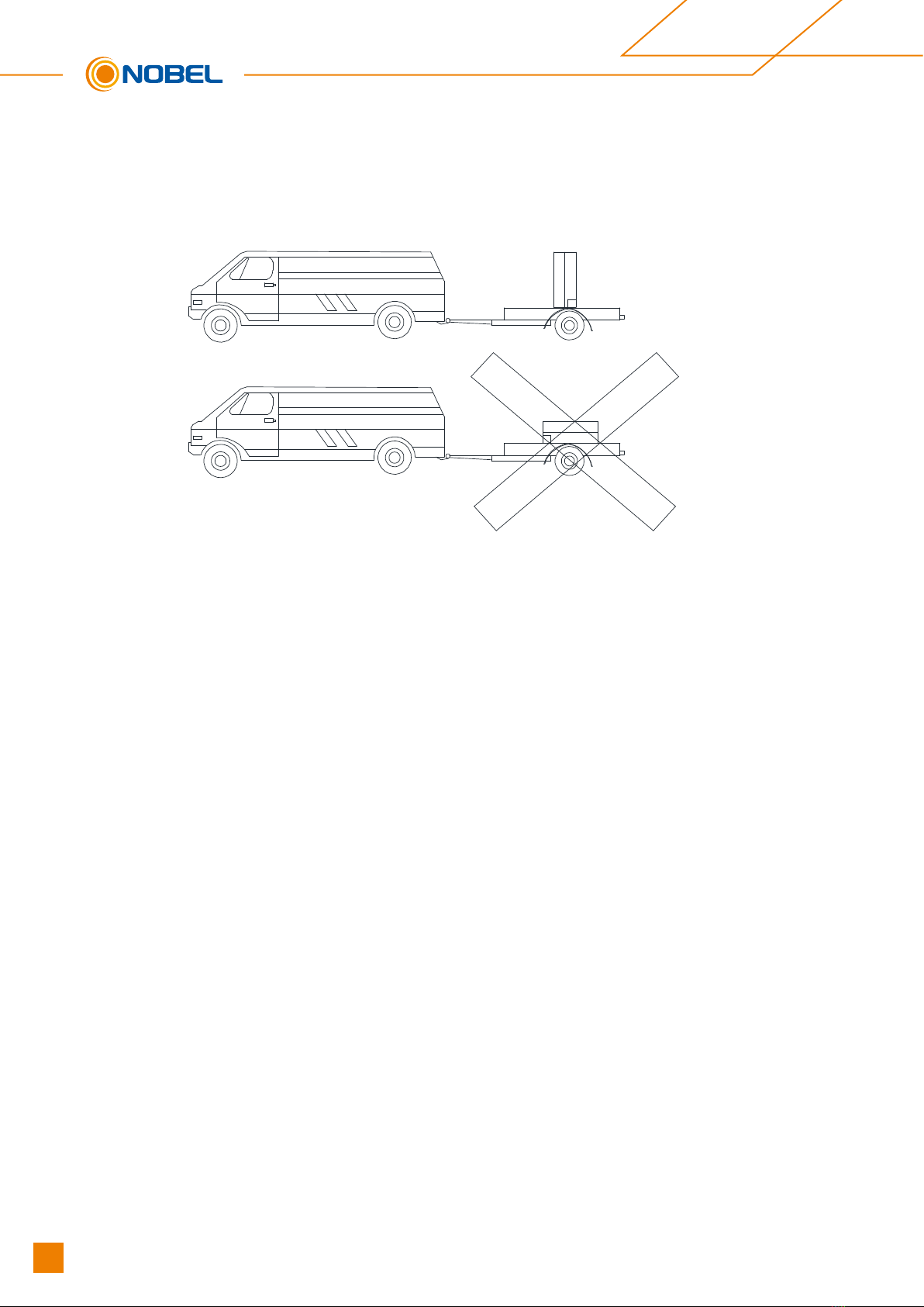
The heat pump must be transported, handled and stored vertically. Tipping the machine
may cause the compressor or other components damage.
Do not twist, loosen or pull the external electric cables of the heat pump.
Do not insert any sharp objects through the fan grille or into the fan itself.
Do not wash the interior of the heat pump with water as this may result in electric
shock or fire. For any cleaning and /or maintenance operations, disconnect the main
power supply.
2
2
.
.
4
4
F
F
r
r
e
e
e
e
z
z
e
e
p
p
r
r
o
o
t
t
e
e
c
c
t
t
i
i
o
o
n
n
w
w
a
a
r
r
n
n
i
i
n
n
g
g
s
s
The heat pump is a machine that is installed in the exterior of the house, so that it will
be exposed to the extreme climatic conditions of cold in the periods of frost. Due to
this, it is of paramount importance that this type of machine is protected against such frost.
The freezing of the water inside the heat pump causes the heat pump to breakdown,
with the subsequent interruption of its operation and major economic expenses
involving its repair.
It is mandatory to use a safety system in the installation to prevent the freezing of the
water in the machine. We proposes the use of glycol in the water circuit of the heat
pump, or some antifreeze valve system to empty the installation in conditions of low
temperatures. Carefully read the Freeze Protection section in this manual for more
detailed information on these systems. We will not cover damages caused by the lack
of any of these antifreeze safety systems.
The electronic controller of the heat pump has a function for protection against the
freezing of the water in its interior in periods of frost. For this function to remain active
and on alert, the heat pump must be connected to the mains and have a power supply,
even if it is switched off or not in use.
A water filter should be installed in the installation, in order to avoid obstructions in the water
circuit of the heat pump. It must be installed in the return circuit of the heat pump and MUST
be installed before filling and circulating the water through the installation. The water filter
should be checked and cleaned, if necessary, at least once a year. IN new installations,
however, it is advisable to check it within the first few months of its commissioning.

Multifunctional Heat Pump R32
5
Technical Manual - Multifunctional Heat Pump R32
- 6-
3 System description
The unit is a monoblock (single unit) air/water heat pump, specially designed for the
colder climate. There is no need for bore holes and usually the system can be installed
within 1 day.
The unit can both heat hot water effectively at high outdoor temperatures and give a high
output to the heating system at low outdoor temperatures. If the outdoor temperature drops to
a level lower than minus 0℃ (factory setting), the auxiliary heater switches on to ensure the
heat pump unit works normally. The unit is also capable of cooling in the summer. The heat
pump controller is an intelligent wired system. The unit is rated as 6KW/9KW/12KW/18KW.
The Material/components are chosen to provide a long service life and to fully withstand
harsh outdoor conditions.
The unit has two different installation options:
1). Space heating/cooling + DHW (Domestic hot water)
2). Space heating/cooling only or DHW only

6Technical Manual - Multifunctional Heat Pump R32
- 7-
1 2
3 4
5 6
7 8
9 10
11 12
13 14
15 16
17 18
19 20
21
Top cover Evaporator
Electrical box
Right side support
Electrical box support
Plate type heat exchanger
Base plate
Plate type heat exchanger support
Front plate
Mid-support plate
Fan motor
Left side pore plate 22
Evaporator
Behind plate
Expansion vessel
Compressor
Water pump
Right side service plate
Front service plate
Fan grille
Fan blade
Fan motor support
Left side support
4
4
T
T
e
e
c
c
h
h
n
n
i
i
c
c
a
a
l
l
s
s
p
p
e
e
c
c
i
i
f
f
i
i
c
c
a
a
t
t
i
i
o
o
n
n
4
4
.
.
1
1
I
I
n
n
t
t
e
e
r
r
n
n
a
a
l
l
V
V
i
i
e
e
w
w
NBL-HPM-NT-AC006-V1 / AC009-V1

Multifunctional Heat Pump R32
7
Technical Manual - Multifunctional Heat Pump R32
- 8-
1 2
3 4
5 6
7 8
9 10
11 12
13 14
15 16
17 18
19 20
21 22
Evaporator
Behind plate
Expansion vessel
Compressor
Water pump
Base plate
Plate type heat exchanger support
Front plate
Mid-support plate
Fan motor
Left side pore plate
23
Top cover Evaporator
Electrical box
Right side support
Electrical box support
Gas-liquid separator
Plate type heat exchanger
Right side service plate
Front service plate
Fan grille
Fan blade
Fan motor support
Left side support
NBL-HPM-NT-AC012-V1 / AC012-V3

8Technical Manual - Multifunctional Heat Pump R32
- 9-
1 2
3 4
5 6
7 8
9 10
11 12
13 14
15 16
17 18
19 20
21 22
Evaporator
Behind plate
Expansion vessel
Compressor
Water pump
Right side service plate
Plate type heat exchanger support
Front plate
Mid-support plate
Fan motor
Left side pore plate
23
Top cover Evaporator
Electrical box
Right side support
Electrical box support
Gas-liquid separator
Base plate
Plate type heat exchanger
Front service plate
Fan grille
Fan blade
Fan motor support
Left side support
NBL-HPM-NT-AC018-V1 / AC024-V3

- 10-
4
4
.
.
2
2
D
D
i
i
m
m
e
e
n
n
s
s
i
i
o
o
n
n
s
s
(
(
m
m
m
m
)
)
A
B L
D
C
EE
G
H
F
I
K
J
N
Units A B C D E F G H I J K L N
6/9kW 898 1115 485 415 180 150 470 429 38 60 128 472 62.5
12kW 982 1115 485 415 180 180 470 450 38 60 128 472 62.5
18/23kW 1330 1115 485 415 180 180 470 770 38 60 128 472 62.5
Multifunctional Heat Pump R32
9
Technical Manual - Multifunctional Heat Pump R32

4.3 Specification
Model In
Heating Capacity Range kW 1.2-7.0 2-10 4-14 4-14 6-20 6.5-25
Rated Heating Capacity kW 6.40 9.14 12.20 12.2 18.50 23.00
Rated Heating Input kW 1.34 2.04 2.73 2.73 4.00 5.00
Rated Heating Current A 5.83 8.87 11.87 4.61 17.39 8.44
COP W/W 4.78 4.49 4.47 4.47 4.63 4.60
Rated Cooling Capacity kW 6.25 8.99 11.00 11.00 17.82 21.00
Rated cooling Input kW 1.54 2.41 3.08 3.08 4.92 5.66
Rated cooling Current A 6.70 10.48 13.39 5.20 21.39 9.56
EER W/W 4.05 3.73 3.57 3.57 3.62 3.71
Start Current A 0.5 0.5 1.5 1.5 3.0 5.0
Rated voltage/Frequency/phase V/Hz 230/50/1 230/50/1 230/50/1 380/50/3 230/50/1 380/50/3
Maximum input power kW 2.76 3.45 3.95 4.00 6.21 7.10
Maximum input current A 12 15 17 7 27 12
High pressure protect MPa 4.50
Low pressure protect MPa 0.10
Brand/Type of Compressor /Mitsubishi / Twin Rotary
Refrigerant / R32 R32 R32 R32 R32 R32
Brand of Water pump WILO or GRUNDFOS
Defrost / Auto defrost with 4 way valve
Waterproof grade / IPX4
Noiseat 1m dB(A) 51 54 54 54 56 58
Max water outlet temperature C 60 60 60 60 60 60
Diameter of water connection / DN25 DN25 DN25 DN25 DN25 DN32
Rating water flow m/h 1.1 1.6 2.1 2.1 3.1 4.0
Water pressure drop at rating flow kPa 22 40 50 50 60 40
Min/Max heating water pressure bar 0.5/3.0 0.5/3.0 0.5/3.0 0.5/3.0 0.5/3.0 0.5/3.0
Main board Fuse A 10 10 10 10 10 10
Ambient operational temp. C -15~45 -15~45 -15~45 -15~45 -15~45 -15~45
Water operation temp.(DHW mode ) C 10~60 10~60 10~60 10~60 10~60 10~60
Water operation temp.(Heating mode) C 10~60 10~60 10~60 10~60 10~60 10~60
Water operation temp.(cooling mode) C 10~30 10~30 10~30 10~30 10~30 10~30
Net Dimensions ( L/W/H ) mm 1115/415/8 1115/415/8 1115/415/9 1115/415/9 1115/415/1 1115/415/1
98 98 82 82 332 332
Net Weight kg 80 82 125 125 175 180
Rated test conditions: Heating: DB/WB 7C/6C, In/Out: 30C/35C. Cooling: DB/WB: 35C/24C, In/Out: 23C/18C
-11-
NBL-HPM-NT-
AC006-V1
NBL-HPM-NT-
AC009-V1
NBL-HPM-NT-
AC012-V1
NBL-HPM-NT-
AC012-V3
NBL-HPM-NT-
AC018-V1
NBL-HPM-NT-
AC024-V3
10 Technical Manual - Multifunctional Heat Pump R32
- 12-
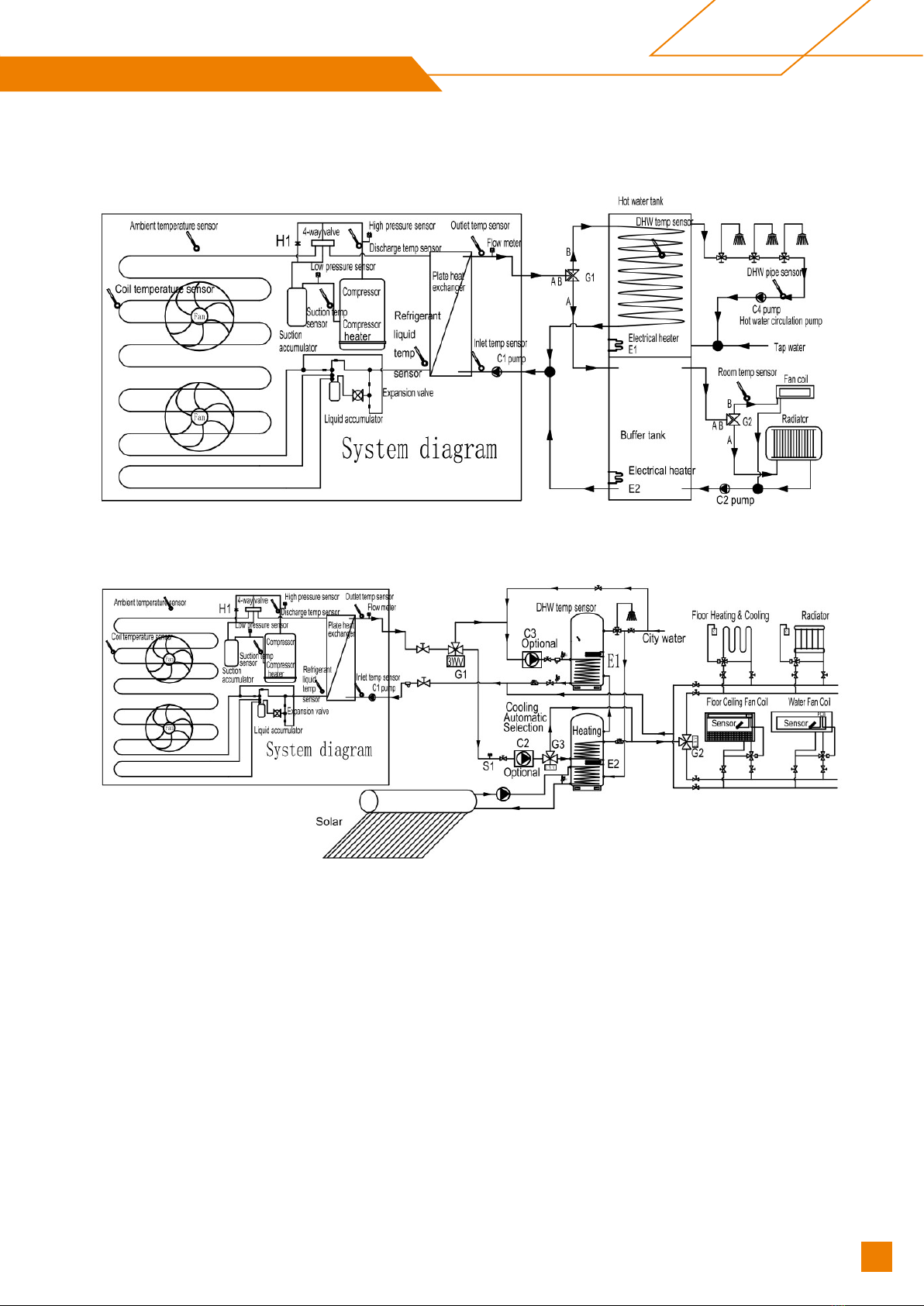
44..44 SSyysstteemm DDrraawwiinngg
P
P
8
8
8
8
=
=
1
1
P
P
6
6
5
5
=
=
1
1
S
S
y
y
s
s
t
t
e
e
m
m
s
s
c
c
h
h
e
e
m
m
a
a
t
t
i
i
c
c
P
P
8
8
8
8
=
=
0
0
P
P
6
6
5
5
=
=
0
0
S
S
y
y
s
s
t
t
e
e
m
m
s
s
c
c
h
h
e
e
m
m
a
a
t
t
i
i
c
c
Multifunctional Heat Pump R32
11
Technical Manual - Multifunctional Heat Pump R32

- 13-
5 Installation
5
5
.
.
1
1
G
G
e
e
n
n
e
e
r
r
a
a
l
l
p
p
o
o
i
i
n
n
t
t
s
s
f
f
o
o
r
r
i
i
n
n
s
s
t
t
a
a
l
l
l
l
a
a
t
t
i
i
o
o
n
n
e
e
n
n
g
g
i
i
n
n
e
e
e
e
r
r
5
5
.
.
1
1
.
.
1
1
P
P
r
r
e
e
p
p
a
a
r
r
a
a
t
t
i
i
o
o
n
n
b
b
e
e
f
f
o
o
r
r
e
e
i
i
n
n
s
s
t
t
a
a
l
l
l
l
a
a
t
t
i
i
o
o
n
n
Make sure the site is large enough to hold all the equipment and has enough
operation space. Measure the hoisting path to ensure that the path to the installation site is
unobstructed and prevent the equipment from reaching the site during installation Confirm
that the power meter capacity and the wire capacity are sufficient and the phase (three-
phase, two-phase) meets the requirements.
Plan the layout of the equipment according to the customers site. And strive to have the
shortest and the most straight water pipe and enough space for operation and maintenance.
For the heat pump with side outlet wind, consider the local wind direction and choose a
reasonable installation direction to avoid the wind direction being opposite. Current
regulations require the heating installation to be inspected before it is commissioned. The
inspection must be carried out by a suitably qualified person and should be documented. If
the heat pump is replaced, the installation must be inspected again. In the event of
installation with unvented (closed) heating systems, Make sure the line has an exhaust valve
(the system comes with an automatic exhaust valve). If necessary, installation engineer may
add additional exhaust valves to the line.
5.1.2 Sitting the heat pump
The heat pump should be firmly fixed to a base, preferably a concrete baseIt is the
most suitable that the right end is 5-10mm higher than the left end .As shown below:
≥100mm
The receiving surface of the device must:
- Allow a solid fixation (preferably concrete).
- Fully support its weight.
- Have a permeable area below the condensate drainage hole
(earth, gravel bed, sand, etc ).
12 Technical Manual - Multifunctional Heat Pump R32

- 14-
- Do not transmit any vibration to the home, recommending the installation of the
anti-vibration dampers supplied with the heat pump.
In case of installing the device on wall mounts, it will be especially important to isolate the
machine from the transmission of vibrations and noise inside the house, it may be necessary
to install more suitable anti-vibration dampers for the wall mount in addition to those supplied
with the heat pump. Nevertheless, the installation on the ground is the most advisable.
Straighten the heat pump well to ensure that the condensate water cannot exit through any
paths other than the intended drain hole.
Fasten it firmly using 4 sets of M12 bolts suitable for the base material, with nuts and
washers (available on the market). Make sure that the protruding distance of the bolt
does not exceed 10mm inside the metallic support of the device(leg).
5
5
.
.
1
1
.
.
3
3
L
L
o
o
c
c
a
a
t
t
i
i
o
o
n
n
r
r
e
e
q
q
u
u
i
i
r
r
e
e
m
m
e
e
n
n
t
t
s
s
b
b
e
e
t
t
w
w
e
e
e
e
n
n
m
m
a
a
c
c
h
h
i
i
n
n
e
e
a
a
n
n
d
d
b
b
u
u
i
i
l
l
d
d
i
i
n
n
g
g
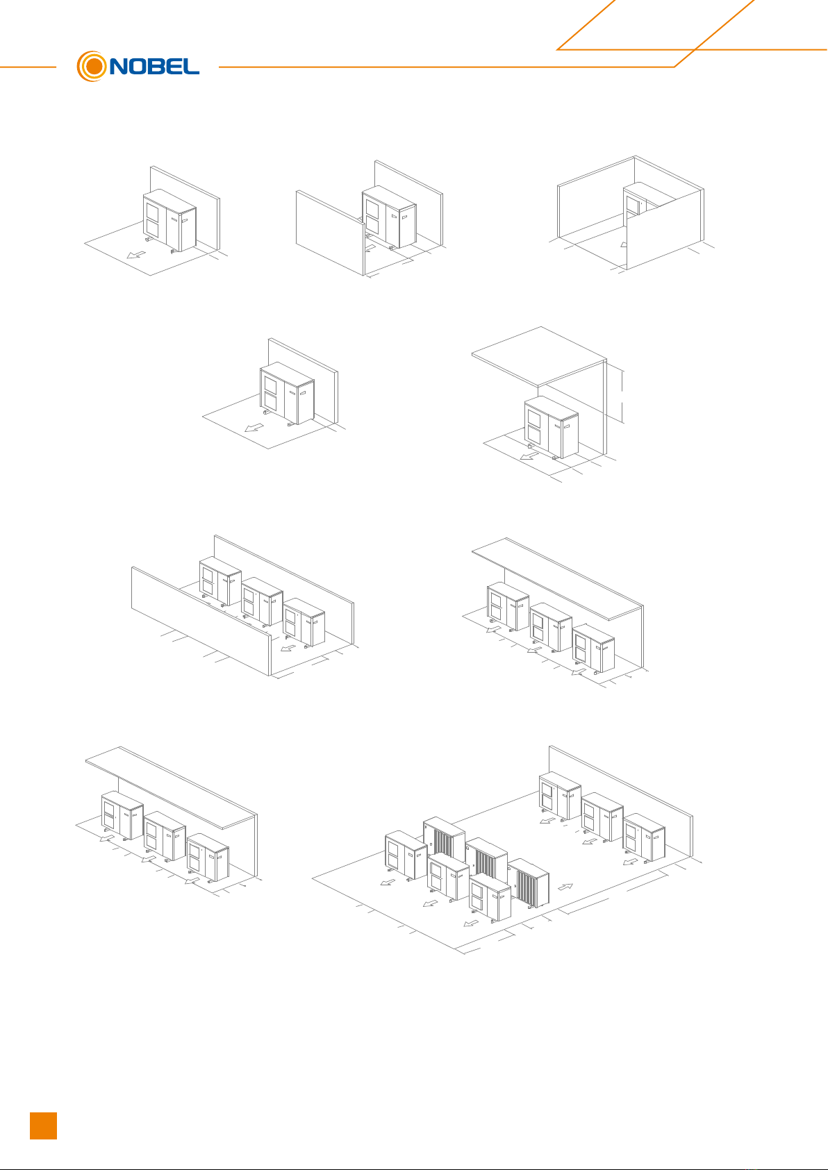
The heat pump must be installed exclusively outside the home and, where possible, in
a completely clear area. If a protection is needed around the appliance, it should
have wide openings on the 4 sides and the installation separations indicated in the
following figure must be respected. No obstacle should prevent the circulation of air
through the evaporator and the fan outlet.
Multifunctional Heat Pump R32
13
Technical Manual - Multifunctional Heat Pump R32
- 15-
≥ 2 00
≥ 3 50
≥ 10 00
≥ 3 50
≥ 4 00
≥ 2 00
≥ 2 00
≥ 3 50
≥ 1000
M a x . 500
Mininum separations for the installation of a unit(mm)
≥ 5 00
≥ 15 00
≥ 4 00
≥ 4 00
≥ 5 00
M a x . 300
≥ 4 00
≥ 4 00
≥ 5 00
M a x . 300
≥ 4 00
≥ 4 00
≥ 15 00
≥ 30 00
≥ 5 00
≥ 6 00
≥ 4 00
≥ 4 00
Mininum separations for the installation of multiple units in the same location(mm)
14 Technical Manual - Multifunctional Heat Pump R32
- 16-
Consult with the user before choosing the location of the device. It should not be
placed next to sensitive walls, such as on the wall next to a bedroom. Make sure that
the location of the heat pump is not disruptive to neighbors (sound level, air currents
generated, low temperature of the air blown with risk of freezing plants in the path,
etc.).
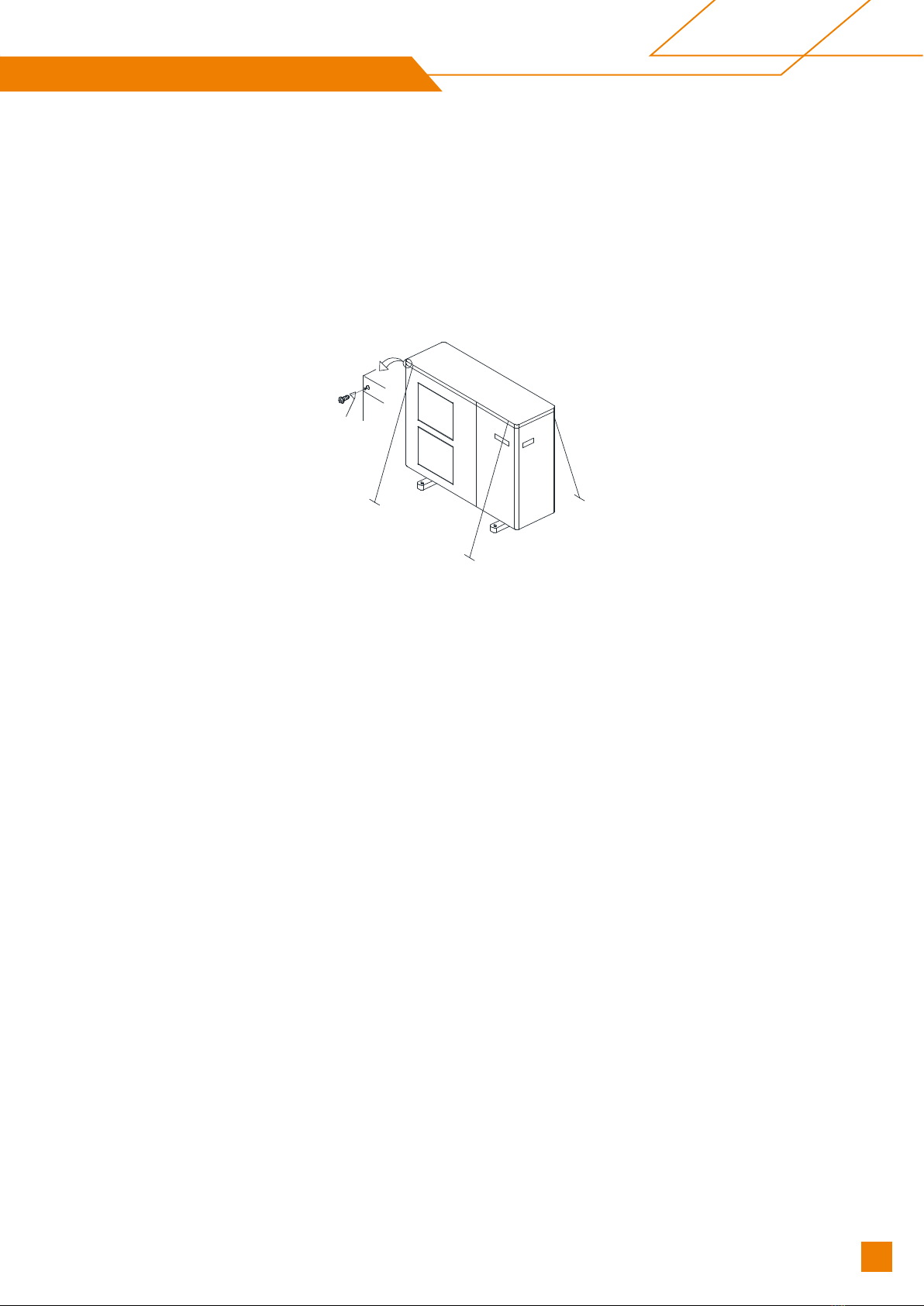
Choose a location that preferably has sunlight and is protected from strong and cold
winds. If the heat pump is exposed to gusts of wind that make it possible to overturn
it, it should be supported by suitable guys, as indicated in the figure.
The device must be sufficiently accessible for subsequent installation and maintenance
work. Make sure that the passage of the hydraulic and electrical connections to the
interior of the house is possible and comfortable. The spacing measures indicated in
the figure above are those strictly necessary to ensure correct operation of the device;
however, sometimes, it will be essential to provide more space for maintenance work.
The heat pump is a device specially designed for outdoor installation. Nevertheless,
avoid installing it in a place where it may be exposed to significant water stains or
spills (e.g. under a faulty gutter, near gas outlets, etc.) . Move the appliance away
from heat sources and flammable products. In areas where abundant and copious
snowfalls occur, special care must be taken to protect the heat pump from possible
obstructions due to accumulation of snow around it. The obstruction of the air inlet and/
or outlet of the machine due to the accumulation of snow may cause malfunction of the
unit and possible breakdowns. The heat pump must be raised at least 100 millimeters
above the maximum expected snow level. In turn, the roof should be protected from
accumulation of snow, by means of a roof projecting from the building or a similar
structure.
5
5
.
.
1
1
.
.
4
4
C
C
o
o
n
n
d
d
e
e
n
n
s
s
a
a
t
t
e
e
d
d
r
r
a
a
i
i
n
n
a
a
g
g
e
e
In normal operation, the heat pump can evacuate large amounts of water, for which the
heat pump provides a hole in the bottom of the appliance. Be sure not to obstruct this
hole during the installation process of the appliance.
Multifunctional Heat Pump R32
15
Technical Manual - Multifunctional Heat Pump R32

- 17-
Preferably install the device in a well-drained place. To do this, it is advisable to
provide a bed of gravel, sand or similar materials below said hole. If the drain hole of
the heat pump is covered by a mounting base or by the floor, lift the unit to leave a
free space of at least 100mm below it.
If it is installed on a terrace or facade, the condensate outlet must be led to a drain to
avoid inconvenience and/or damage caused by the dripping of condensate water. If the
installation is carried out in a region where the temperature can be below 0 for a long
period of time
5
5
.
.
1
1
.
.
5
5
A
A
c
c
c
c
e
e
s
s
s
s
o
o
r
r
i
i
e
e
s
s
s
s
u
u
p
p
p
p
l
l
i
i
e
e
d
d
The following accessories are supplied in the interior of the heat pump. Be fore
proceeding with the installation of the machine, make sure that you receive them and
that they are in good condition.
Documentation:
Inside the machine, open the front door to find the documentation bag, where all the
manuals and documents necessary for the use and installation of the heat pump are
included.
Controller:
It is supplied inside the machine and can be found by removing cover of the electronic
boards. Before connecting the power supply to the machine, the controller should be
installed inside the house. See 6.3.1 for the physical drawing
Drain valve:
It is supplied inside the machine, tied with a flange to one leg of the compressor.
Front
Behind
16 Technical Manual - Multifunctional Heat Pump R32
- 18-
This key must be installed in the drain socket on the back of the heat pump before
filling the water in the heating/cooling circuit.
4x Anti-vibration dampers:
Four units are supplied in a bag stuck on the back of the machine, next to the drain
socket.
5
5
.
.
1
1
.
.
6
6
C
C
o
o
n
n
t
t
r
r
o
o
l
l
l
l
e
e
r
r
The unit is equipped with an external electronic controller that handles all functions
necessary for heat pump operations. Defrosting, stop at max/min temperature,
connection of the compressor heater as well as enabling the aux electrical heater,
monitoring of motor protection and pressure sensors are all controlled.
The number of starts and the operating time after this power-on can also be read. The
controller is set during installation and can be used during a service. Under normal operating
conditions the home owner does not need to have access to the controller. The unit has an
integrated electronic outlet water temperature sensor that limits the outlet temperature up to
60℃.
5
5
.
.
2
2
I
I
n
n
s
s
t
t
a
a
l
l
l
l
a
a
t
t
i
i
o
o
n
n
d
d
e
e
s
s
i
i
g
g
n
n
The unit can be installed in several different ways.
The safety equipment must be installed in accordance with current regulations for all
installation options.
When connecting with the unit, the total water volume in the heat pump pipe system
and buffer tank must be at least 10 liters per 1 kW of output.
Multifunctional Heat Pump R32
17
Technical Manual - Multifunctional Heat Pump R32

- 19-
A
A
)
)
N
N
B
B
L
L
-
-
H
H
P
P
M
M
-
-
N
N
T
T
-
-
A
A
C
C
0
0
0
0
6
6
-
-
V
V
1
1
/
/
A
A
C
C
0
0
0
0
9
9
-
-
V
V
1
1
/
/
A
A
C
C
0
0
1
1
2
2
-
-
V
V
1
1
/
/
V
V
3
3
/
/
A
A
C
C
0
0
1
1
8
8
-
-
V
V
1
1
S
S
p
p
a
a
c
c
e
e
H
H
e
e
a
a
t
t
i
i
n
n
g
g
/
/
C
C
o
o
o
o
l
l
i
i
n
n
g
g
+
+
D
D
H
H
W
W
B
B
)
)
N
N
B
B
L
L
-
-
H
H
P
P
M
M
-
-
N
N
T
T
-
-
A
A
C
C
0
0
0
0
6
6
-
-
V
V
1
1
/
/
A
A
C
C
0
0
0
0
9
9
-
-
V
V
1
1
/
/
A
A
C
C
0
0
1
1
2
2
-
-
V
V
1
1
/
/
V
V
3
3
/
/
A
A
C
C
0
0
1
1
8
8
-
-
V
V
1
1
S
S
p
p
a
a
c
c
e
e
H
H
e
e
a
a
t
t
i
i
n
n
g
g
/
/
C
C
o
o
o
o
l
l
i
i
n
n
g
g
M
M
o
o
d
d
e
e
O
O
n
n
l
l
y
y
18 Technical Manual - Multifunctional Heat Pump R32

- 20-
C
C
)
)
2
2
x
x
N
N
B
B
L
L
-
-
H
H
P
P
M
M
-
-
N
N
T
T
-
-
A
A
C
C
0
0
0
0
6
6
-
-
V
V
1
1
/
/
A
A
C
C
0
0
0
0
9
9
-
-
V
V
1
1
/
/
A
A
C
C
0
0
1
1
2
2
-
-
V
V
1
1
/
/
V
V
3
3
/
/
A
A
C
C
0
0
1
1
8
8
-
-
V
V
1
1
I
I
n
n
s
s
t
t
a
a
l
l
l
l
a
a
t
t
i
i
o
o
n
n
.
.
S
S
p
p
a
a
c
c
e
e
H
H
e
e
a
a
t
t
i
i
n
n
g
g
/
/
C
C
o
o
o
o
l
l
i
i
n
n
g
g
+
+
D
D
H
H
W
W
D
D
)
)
3
3
x
x
N
N
B
B
L
L
-
-
H
H
P
P
M
M
-
-
N
N
T
T
-
-
A
A
C
C
0
0
0
0
6
6
-
-
V
V
1
1
/
/
A
A
C
C
0
0
0
0
9
9
-
-
V
V
1
1
/
/
A
A
C
C
0
0
1
1
2
2
-
-
V
V
1
1
/
/
V
V
3
3
/
/
A
A
C
C
0
0
1
1
8
8
-
-
V
V
1
1
I
I
n
n
s
s
t
t
a
a
l
l
l
l
a
a
t
t
i
i
o
o
n
n
.
.
S
S
p
p
a
a
c
c
e
e
H
H
e
e
a
a
t
t
i
i
n
n
g
g
/
/
C
C
o
o
o
o
l
l
i
i
n
n
g
g
+
+
D
D
H
H
W
W
Multifunctional Heat Pump R32
19
Technical Manual - Multifunctional Heat Pump R32
- 21-
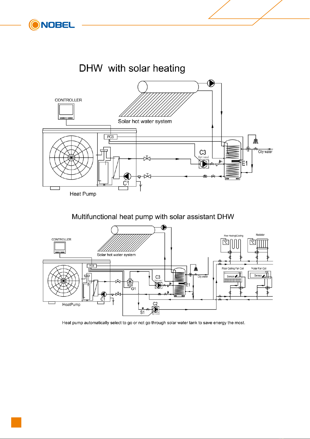
Solar Application 1
Solar Application 2
20 Technical Manual - Multifunctional Heat Pump R32
This manual suits for next models
1
Other Nobel Heat Pump manuals

Popular Heat Pump manuals by other brands


Rheem
Rheem 953060DP Owner's guide and installation instructions

Maritime Geothermal
Maritime Geothermal NORDIC W Series Product application, installation and service manual

Kaisai
Kaisai KHY-12PY3 user manual

ANTEK
ANTEK AIR MAGNA 100 Installation and maintenance instructions

Daishiba
Daishiba DSP?45HCA user manual

OEM
OEM DC BWA-SS-9 Installation and maintenance instructions