Nobel R290 User guide

Technical Manual
Installation, maintenance & use instructions
Multifunctional
Heat Pump R290


CONTENTS
1. GENERAL ............................................................................................................ 4
2. SAFETY WARNINGS ........................................................................................... 4
2.1. Usage and installation warnings ........................................................................... 4
2.2. Personal safety warnings...................................................................................... 5
2.3. Transport, storage and handling warnings............................................................ 6
2.4. Freeze protection warnings .................................................................................. 6
3. SYSTEM DESCRIPTION ..................................................................................... 7
4. INSTALLATION .................................................................................................... 8
4.1. General points for installation engineer ................................................................ 8
4.1.1.Preparation before installation .............................................................................. 8
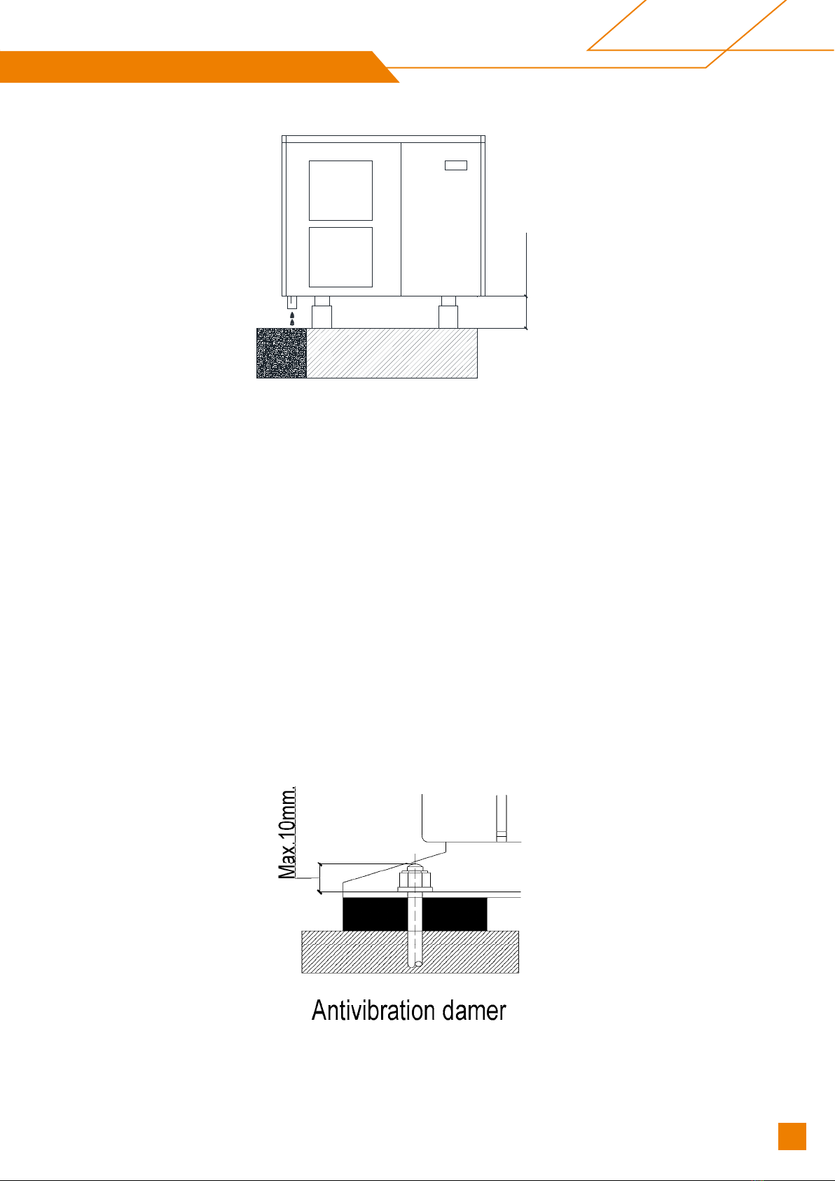
4.1.2.Sitting the heat pump............................................................................................ 8
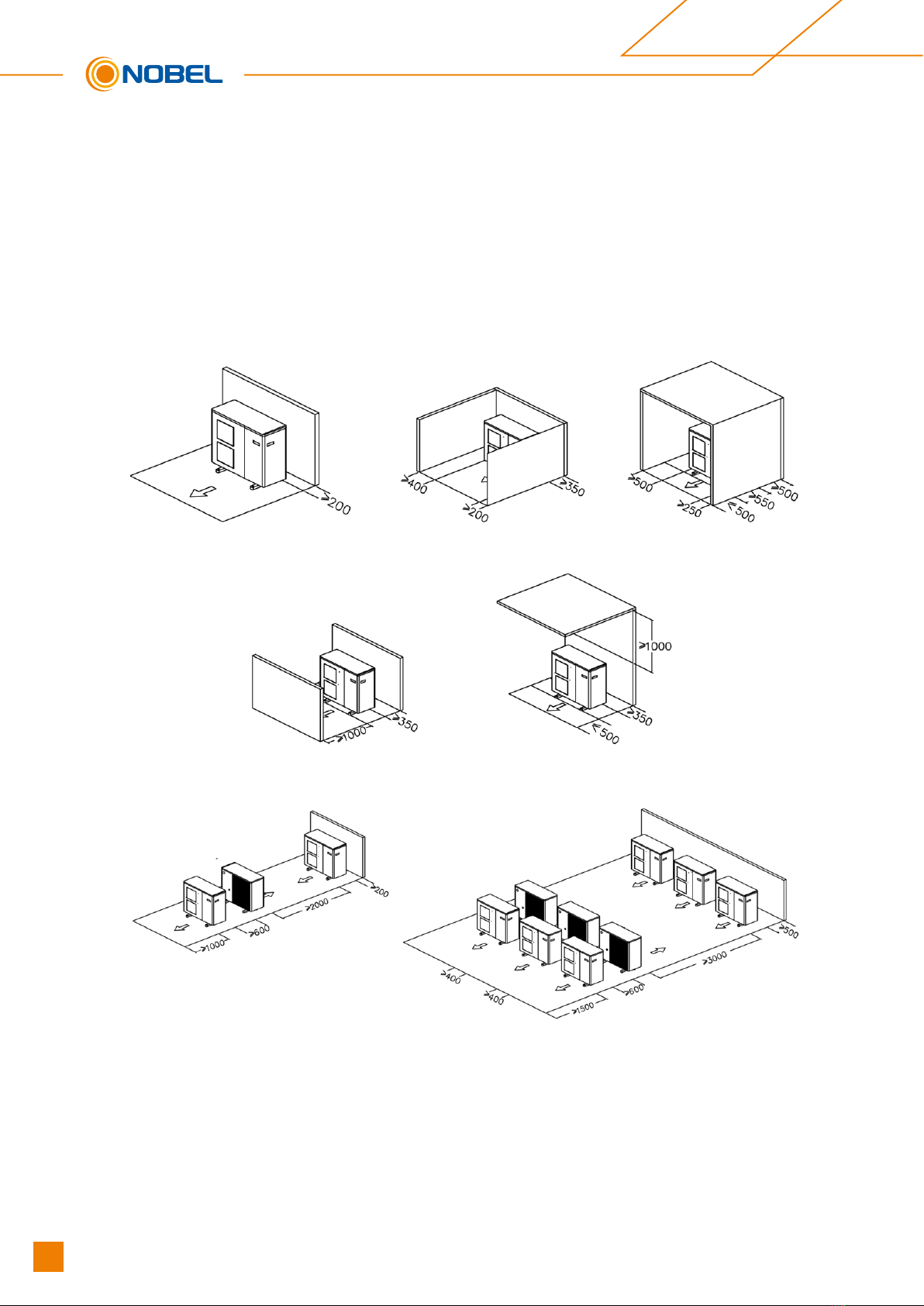
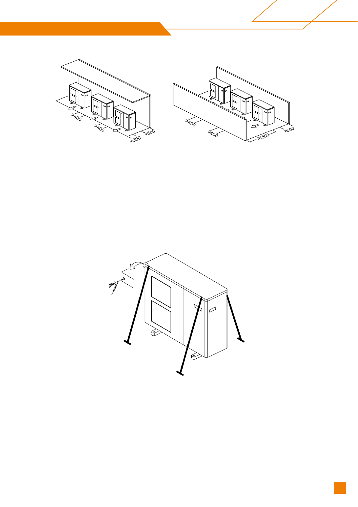
4.1.3.Location requirements between machine and building....................................... 10
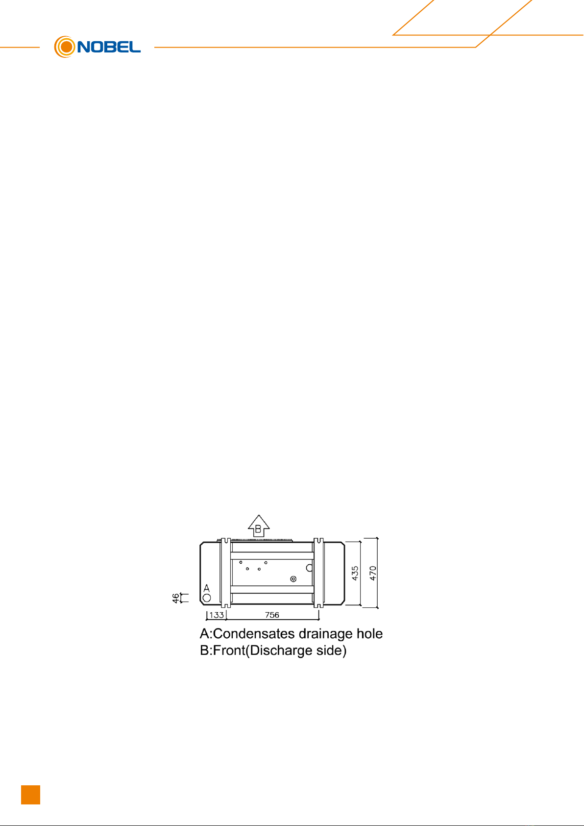
4.1.4.Condensate drainage ......................................................................................... 12
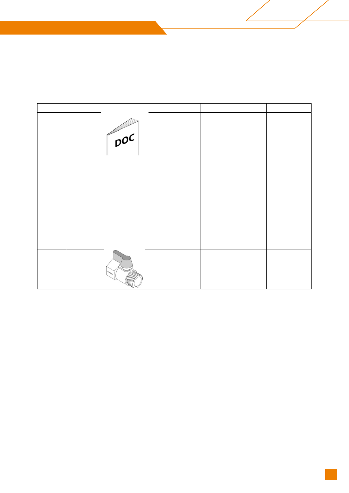
4.1.5.Accessories supplied .......................................................................................... 13
4.1.6.Controller ............................................................................................................ 13
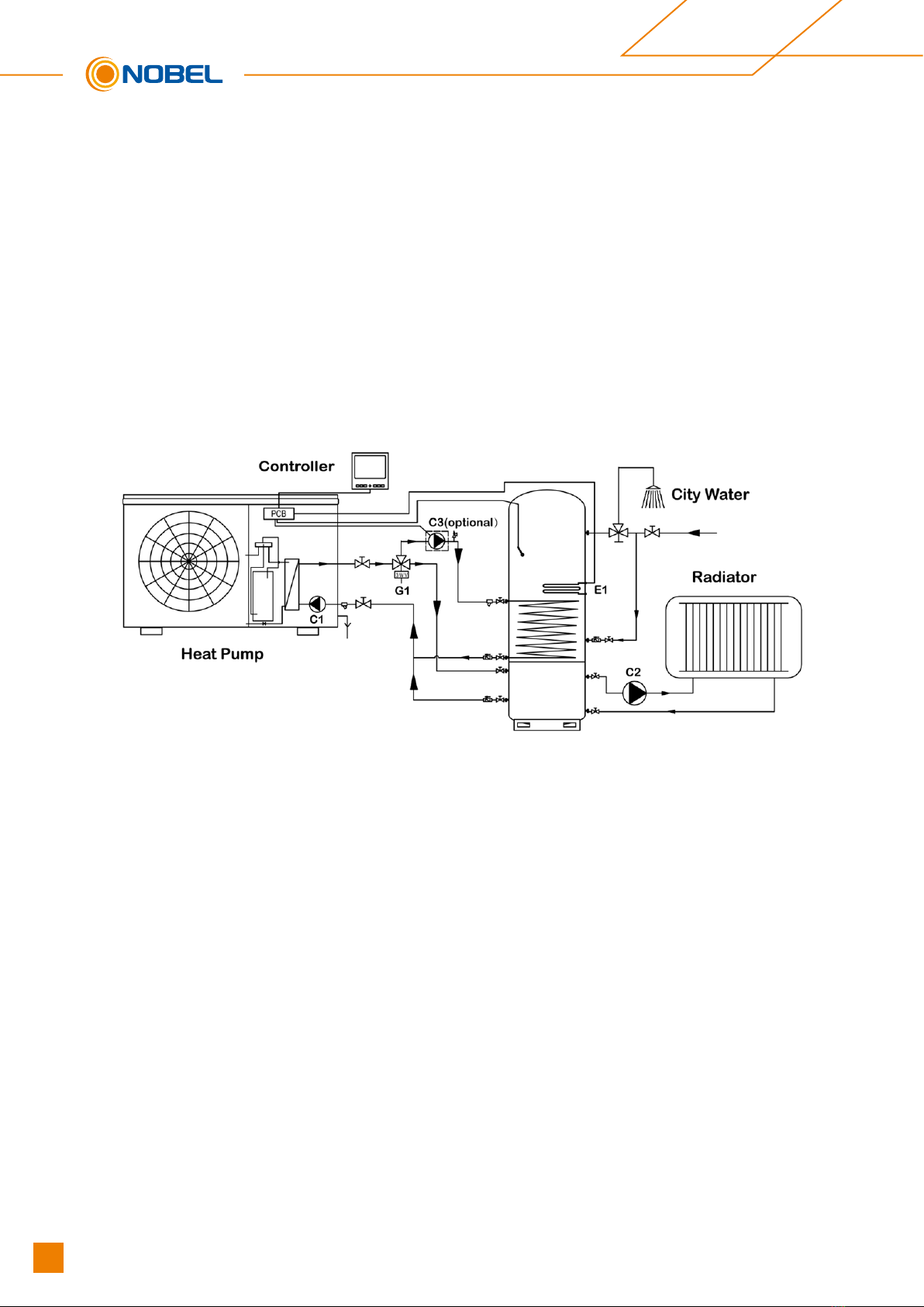
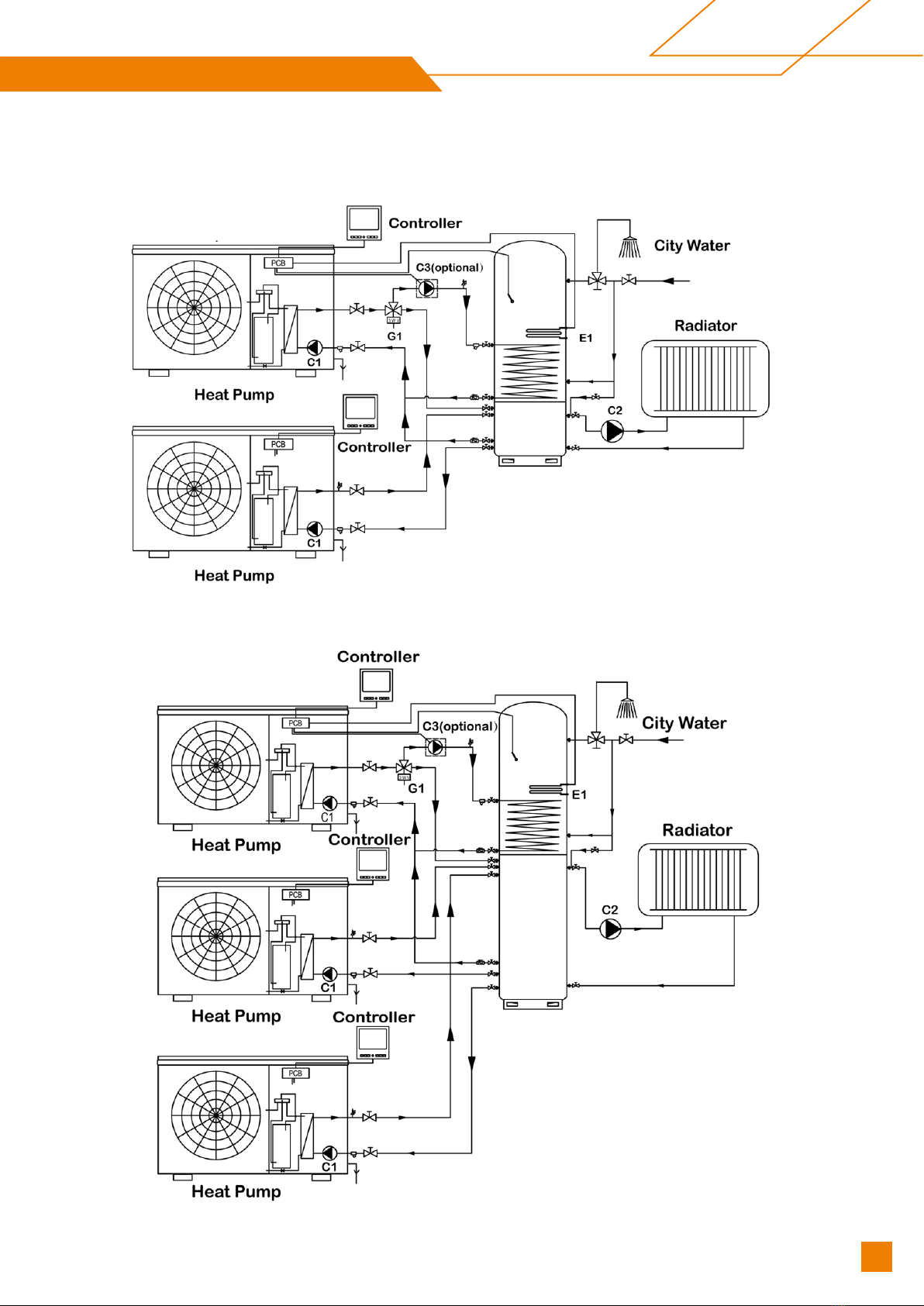
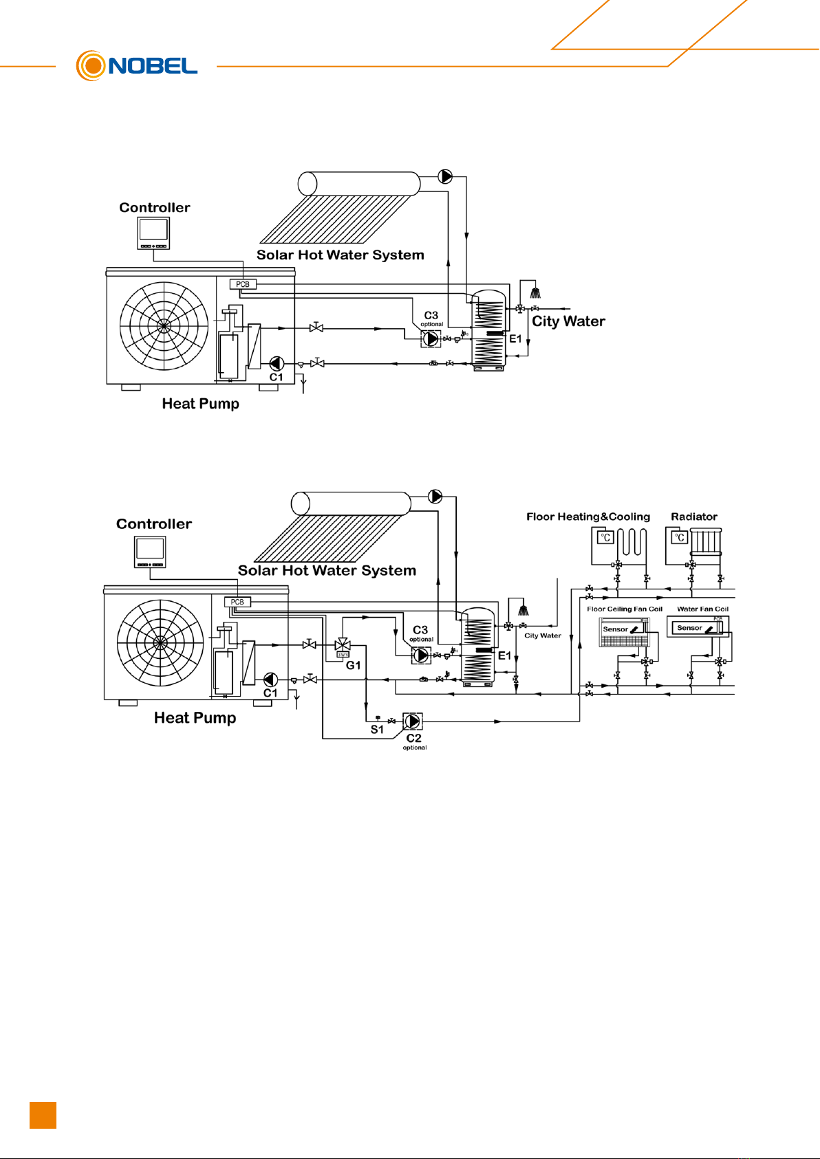
4.2. Installation design ............................................................................................... 14
4.3. Pipe connection .................................................................................................. 17
4.4. Electrical connection........................................................................................... 18
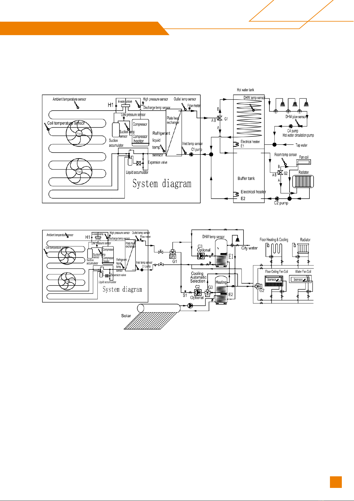
4.4.1.System diagram.................................................................................................. 19
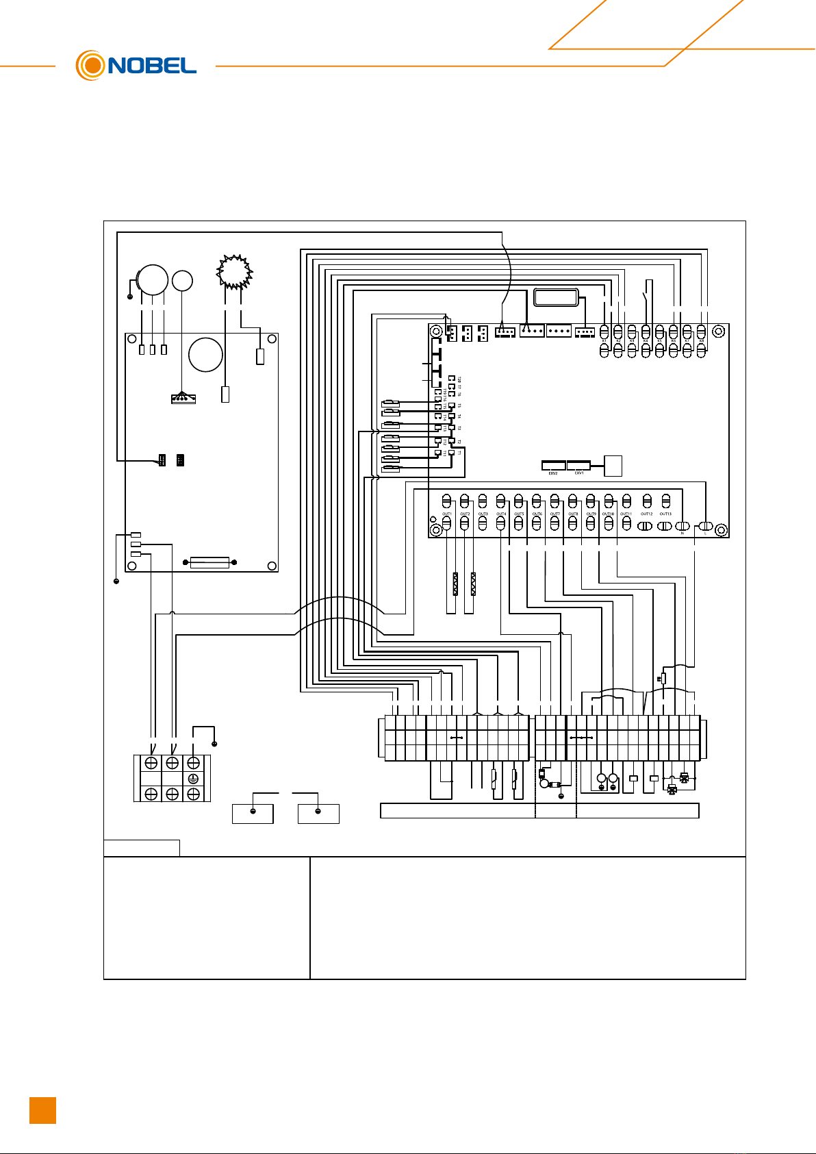
4.4.2.Wiring diagram.................................................................................................... 20
4.4.3.Auxiliary electrical heater connection ................................................................. 24
4.4.4.Installation drawing ............................................................................................. 24
4.4.5.DHW anti-freeze ................................................................................................. 26
4.4.6.AC anti-freeze..................................................................................................... 26
4.5. Commissioning ................................................................................................... 26
4.5.1.Preparations ....................................................................................................... 26
4.5.2.Inspection before start up ................................................................................... 27
4.5.3.Start up and commissioning ............................................................................... 27
5. CONTROLLER................................................................................................... 28
5.1. Electric parts control program working theory .................................................... 28
5.2. Operating mode principle.................................................................................... 29
5.3. Wired controller................................................................................................... 30
5.3.1.Main interface ..................................................................................................... 30
5.3.2.Buttonsdenitionandaction............................................................................... 31
5.4. Night mode ......................................................................................................... 43
5.5. Communication with controller............................................................................ 43
5.6. Denitionofabbreviationdisplayedinthecontroller .......................................... 43
6. TECHNICAL SPECIFICATION........................................................................... 45
6.1. Internalview........................................................................................................ 45
6.2. System drawing .................................................................................................. 47
6.3. Dimensions(mm)................................................................................................. 48
6.4. Specication ....................................................................................................... 49
7. MAINTENANCE ................................................................................................. 50
8. HOW TO GET THE MOST OUT OF YOUR HEAT PUMP ................................. 51
Appendix I: WI-FI operation ............................................................................. 52
Multifunctional Heat Pump R290
3
Technical Manual - Multifunctional Heat Pump R290

1
1 GENERAL
Thank you for choosing Master Heat. This is a heat pump capable of providing the ideal
level of comfort for your home, always with a suitable hydraulic installation.
The unit is an air source heat pump for space heating/cooling and sanitary water heater
for houses, apartment blocks and small industrial premises. Outdoor air is used as a heat
source creating free energy to heat your home.
This manual forms an essential part of the product and it must be given to the user. Read
the warnings and recommendations in the manual carefully, as they contain important
information on the safety, use and maintenance of the installation.
This heat pump must be installed by qualified personnel only, in accordance with the
legislation in force and following the manufacturer’s instructions.
The start-up of this heat pump and any maintenance operations must be carried only by
qualified personnel only.
Incorrect installation of this heat pump could result in damage to people, animals or
property, and the manufacturer will not be held liable in such cases.
2 SAFETY WARNINGS
2.1 Usage and installation warnings
The heat pump must be installed by personnel authorized by the Ministry of Industry, in
compliance with the applicable laws and regulations. The precautions detailed here
cover very important issues. Please be sure to follow them carefully.
Read carefully this instruction manual and keep it in a safe, easily-accessible place. The
manufacturer will not be liable for any damages caused by failure to follow these
instructions.
This heat pump is suitable for use in both heating and cooling installations and can be
combined with fan coils, underfloor heating/cooling, low-temperature radiators, and
domestic hot water tanks (optional). It must be connected to a heating/cooling installation
and/or a domestic hot water distribution network and compatible with its performance
and power.
4Technical Manual - Multifunctional Heat Pump R290

2
This appliance must only be used for the purpose for which it has been expressly
designed. Any other use is considered unsuitable and therefore hazardous. The
manufacturer shall not be considered liable under any circumstances for damage caused
by unsuitable, erroneous or irrational use.
Remove all the packaging and check the contents are complete. In case of doubt, do not
use the heat pump. Contact your supplier. Keep the packaging elements out of reach of
children, as they can be dangerous.
Improper installation or placement of equipment or accessories may cause electrocution,
short circuit, leakage, fire, or other damage to the equipment. Use only accessories or
optional equipment designed specifically to work with the products presented in this
manual. Do not modify, replace or disconnect any safety or control device without first
consulting the manufacturer.
When it is decided not to use any more the heat pump, disable the parts that could
represent a potential hazard.
2.2 Personal safety warnings
Always wear appropriate personal protective equipment (gloves, safety goggles, etc.)
when performing installation and/or maintenance on the unit.
Do not touch any switch with wet fingers. Touching a switch with wet fingers may cause
electric shock. Before accessing the electrical components of the heat pump, disconnect
the main power supply completely.
Disconnect all electricity sources before dismantling the cover panel from the electric
panel or before making any connections or accessing electrical parts.
To avoid electrocutions, be sure to turn off the power for 1 minute (or more) before
servicing the electrical parts. Even after 1 minute, always measure the voltage at the
terminals of the main circuit capacitors and other electrical parts before touching them
and make sure that the voltage is equal to or less than 50 V dc.
When the cover panels are disassembled, the energized parts can be easily accessed.
Never leave the unit unattended during installation or during maintenance work when the
cover panel is removed.
Do not touch the refrigerant pipes, water piping, or internal parts during and immediately
after operation. Pipes and internal parts may be excessively hot or cold, depending on
the use of the unit.
Multifunctional Heat Pump R290
5
Technical Manual - Multifunctional Heat Pump R290

3
The hands may be burned by cold or heat in case of improperly touching pipes or internal
parts. To avoid injury, wait until the pipes and internal parts return to their normal
temperature. Alternatively, if access is required, be sure to wear appropriate safety
gloves.
2.3 Transport, storage and handling warnings
The heat pump must be transported, handled and stored vertically. Tipping the machine
may cause the compressor or other components damage.
Do not twist, loosen or pull the external electric cables of the heat pump. Do not insert
any sharp objects through the fan grille or into the fan itself.
Do not wash the interior of the heat pump with water as this may result in electric shock
or fire. For any cleaning and /or maintenance operations, disconnect the main power
supply.
2.4 Freeze protection warnings
The heat pump is a machine that is installed in the exterior of the house, so that it will be
exposed to the extreme climatic conditions of cold in the periods of frost. Due to this, it is
of paramount importance that this type of machine is protected against such frost. The
freezing of the water inside the heat pump causes the heat pump to breakdown, with the
subsequent interruption of its operation and major economic expenses involving its
repair.
It is mandatory to use a safety system in the installation to prevent the freezing of the
water in the machine. We propose the use of glycol in the water circuit of the heat pump,
or some antifreeze valve system to empty the installation in conditions of low
temperatures. Carefully read the “Freeze Protection” section in this manual for more
6Technical Manual - Multifunctional Heat Pump R290

4
detailed information on these systems. We will not cover damages caused by the lack of
any of these antifreeze safety systems.
The electronic controller of the heat pump has a function for protection against the
freezing of the water in its interior in periods of frost. For this function to remain active
and on alert, the heat pump must be connected to the mains and have a power supply,
even if it is switched off or not in use.
A water filter should be installed in the installation, in order to avoid obstructions in the
water circuit of the heat pump. It must be installed in the return circuit of the heat pump
and MUST be installed before filling and circulating the water through the installation.
The water filter should be checked and cleaned, if necessary, at least once a year. IN
new installations, however, it is advisable to check it within the first few months of its
commissioning.
3 SYSTEM DESCRIPTION
1) The unit is a monoblock (single unit) air/water heat pump, specially designed for
the colder climate. There is no need for bore holes and usually the system can be
installed within 1 day.
2) The unit can both heat hot water effectively at high outdoor temperatures and give
a high output to the heating system at low outdoor temperatures. If the outdoor
temperature drops to a level lower than minus 0°C (factory setting), the auxiliary
heater switches on to ensure the heat pump unit works normally. The unit is also
capable of cooling in the summer. The heat pump controller is an intelligent wired
system.
3) The unit is rated as 6KW/9KW/12KW/16KW. The Material/components are chosen
to provide a long service life and to fully withstand harsh outdoor conditions.
4) The unit has two different installation options:
Space heating/cooling + DHW (Domestic hot water)
Space heating/cooling only or DHW only
Multifunctional Heat Pump R290
7
Technical Manual - Multifunctional Heat Pump R290

5
4 INSTALLATION
4.1 General points for installation engineer
4.1.1 Preparation before installation
1) Make sure the site is large enough to hold all the equipment and has enough
operation space.
2) Measure the hoisting path to ensure that the path to the installation site is
unobstructed and prevent the equipment from reaching the site during
Installation.
3) Confirm that the power meter capacity and the wire capacity are sufficient and
the phase (three-phase, two-phase) meets the requirements.
4) Plan the layout of the equipment according to the customer’s site. And strive to
have the shortest and the straightest water pipe and enough space for
operation and maintenance.
5) For the heat pump with side outlet wind, consider the local wind direction and
choose a reasonable installation direction to avoid the wind direction being
opposite.
6) Current regulations require the heating installation to be inspected before it is
commissioned. The inspection must be carried out by a suitably qualified person
and should be documented. If the heat pump is replaced, the installation must be
inspected again. In the event of installation with unvented (closed) heating
systems, make sure the pipeline has an exhaust valve (an automatic air exhaust
valve is included in the heat pump). If necessary, installation engineer may add
additional air exhaust valves to the pipeline.
4.1.2 Sitting the heat pump
1) The heat pump should be firmly fixed to a base, preferably a concrete base,It is
the most suitable that the right end is 5-10mm higher than the left end. As shown
below:
8Technical Manual - Multifunctional Heat Pump R290

6
2) The receiving surface of the device must:
Allow a solid fixation (Preferably concrete).
Fully support its weight.
Have a permeable area below the condensate drainage hole (earth, gravel bed,
sand, etc).
Do not transmit any vibration to the home, recommending the installation of the
anti-vibration dampers supplied with the heat pump.
3) In case of installing the device on wall mounts, it will be especially important to
isolate the machine from the transmission of vibrations and noise inside the
house, it may be necessary to install more suitable anti-vibration dampers for the
wall mount in addition to those supplied with the heat pump. Nevertheless, the
installation on the ground is the most advisable.
4) Straighten the heat pump well to ensure that the condensate water cannot exit
through any paths other than the intended drain hole.
5) Fasten it firmly using 4 sets of M12 bolts suitable for the base material, with nuts
and washers (available on the market). Make sure that the protruding distance of
the bolt does not exceed 10mm inside the metallic support of the device(leg).
≥100mm
Multifunctional Heat Pump R290
9
Technical Manual - Multifunctional Heat Pump R290

7
4.1.3 Location requirements between machine and building
1) The heat pump must be installed exclusively outside the home and, where
possible, in a completely clear area. If a protection is needed around the
appliance, it should have wide openings on the 4 sides and the installation
separations indicated in the following figure must be respected. No obstacle
should prevent the circulation of air through the evaporator and the fan outlet.
Min. separations for the installation of a unit(mm)
10 Technical Manual - Multifunctional Heat Pump R290

8
Min. separations for the installation of multiple units in the same location(mm)
2) Consult with the user before choosing the location of the device. It should not be
placed next to sensitive walls, such as on the wall next to a bedroom. Make sure
that the location of the heat pump is not disruptive to neighbors (sound level, air
currents generated, low temperature of the air blown with risk of freezing plants in
the path, etc.).
3)
Choose a location that preferably has sunlight and is protected from strong and
cold winds. If the heat pump is exposed to gusts of wind that make it possible to
overturn it, it should be supported by suitable guys, as indicated in the figure.
4) The device must be sufficiently accessible for subsequent installation and
maintenance work. Make sure that the passage of the hydraulic and electrical
connections to the interior of the house is possible and comfortable. The spacing
measures indicated in the figure above are those strictly necessary to ensure
correct operation of the device; however, sometimes, it will be essential to
provide more space for maintenance work.
Multifunctional Heat Pump R290
11
Technical Manual - Multifunctional Heat Pump R290

9
5) The heat pump is a device specially designed for outdoor installation.
Nevertheless, avoid installing it in a place where it may be exposed to significant
water stains or spills (e.g. under a faulty gutter, near gas outlets, etc.). Move the
appliance away from heat sources and flammable products.
6) In areas where abundant and copious snowfalls occur, special care must be
taken to protect the heat pump from possible obstructions due to accumulation of
snow around it. The obstruction of the air inlet and/or outlet of the machine due to
the accumulation of snow may cause malfunction of the unit and possible
breakdowns. The heat pump must be raised at least 100 millimeters above the
maximum expected snow level. In turn, the roof should be protected from
accumulation of snow, by means of a roof projecting from the building or a similar
structure.
4.1.4 Condensate drainage
1) In normal operation, the heat pump can evacuate large amounts of water, for
which the heat pump provides a hole in the bottom of the appliance. Be sure not
to obstruct this hole during the installation process of the appliance.
2) Preferably install the device in a well-drained place. To do this, it is advisable to
provide a bed of gravel, sand or similar materials below said hole. If the drain
hole of the heat pump is covered by a mounting base or by the floor, lift the unit to
leave a free space of at least 100mm below it.
3) If it is installed on a terrace or facade, the condensate outlet must be led to a
drain to avoid inconvenience and/or damage caused by the dripping of
condensate water. If the installation is carried out in a region where the
temperature can be below 0°C for a long period of time.
12 Technical Manual - Multifunctional Heat Pump R290

10
4.1.5 Accessories supplied
The following accessories are supplied in the interior of the heat pump. Before
proceeding with the installation of the machine, make sure that you receive them and
that they are in good condition.
Picture Name Qty
①Manual 1
②Controller 1
③Drain valve 1
4.1.6 Controller
1) The unit is equipped with an external electronic controller that handles all
functions necessary for heat pump operations. Defrosting, stop at max/min
temperature, connection of the compressor heater as well as enabling the aux
electrical heater, monitoring of motor protection and pressure sensors are all
controlled.
2) The number of starts and the operating time after this power-on can also be read.
3) The controller is set during installation and can be used during a service. Under
normal operating conditions the home owner does not need to have access to the
controller. The unit has an integrated electronic outlet water temperature sensor
that limits the outlet temperature up to 75°C.
Multifunctional Heat Pump R290
13
Technical Manual - Multifunctional Heat Pump R290

11
4.2 Installation design
Note:
The safety equipment must be installed in accordance with current regulations for all
installation options.
When connecting with the unit, the total water volume in the heat pump pipe system and
buffer tank must be at least 10 liters per KW of output.
The unit can be installed in several different ways:
1) NBL-HPM-HT-AC006-V1, AC009-V1/V3, AC012-V1/V3, AC016 -V1/V3
Space Heating/Cooling + DHW
2) NBL-HPM-HT-AC006-V1, AC009-V1/V3, AC012-V1/V3, AC016 -V1/V3
Space Heating/Cooling Mode Only
14 Technical Manual - Multifunctional Heat Pump R290

12
3) 2 x NBL-HPM-HT-AC006-V1, AC009-V1/V3, AC012-V1/V3, AC016 -V1/V3
Installation. Space Heating/Cooling + DHW
4)
)
3 x NBL-HPM-HT-AC006-V1, AC009-V1/V3, AC012-V1/V3, AC016 -V1/V3
Installation. Space Heating/Cooling + DHW
Multifunctional Heat Pump R290
15
Technical Manual - Multifunctional Heat Pump R290

13
5)
)
DHW with solar heating
6)
)
Multifunctional heat pump with solar assistant DHW
16 Technical Manual - Multifunctional Heat Pump R290

14
4.3 Pipe connection
Schematic diagram of water pipe connection between heat pump and buffer tank.
For the pipe size:
Model Diameter Pipe joint specification Material
6kw
28mm DN25 copper / stainless steel9kw
12kw
16kw 28mm DN32 copper / stainless steel
1) The pipe must be flushed before the heat pump is connected, so that any
contaminants do not damage the components parts.
2) The heating/cooling water inlet and outlet direction must be connected according
to the marked areas on the heat pump.
3) A water filter must be installed in the water circuit of the heat pump, in order to
avoid obstructions or narrowing caused by dirt in the installation. The filter MUST
be installed before filling the installation with water and in the return branch of the
machine, to avoid the entry of dirty water into the heat exchanger (condenser).
The type of filter installed must be adapted to the particular characteristics of
each installation (type and material of the water pipes, type of water used, water
volume of the installation, etc.). The water filter should be checked and cleaned, if
necessary, at least once a year. In new installation, however, it is advisable to
check it within the first few months of its commissioning.
4) A flexible damping pipe must be installed between the heat pump and the buffer
tank to balance the height difference between the machine and the pipe and
reduce the transmission of vibration.
5) We recommend inserting cut-off valves between the installation piping and the
heat pump to simplify maintenance tasks.
6) Leave a free space around the heat pump for carrying out any maintenance and
repair operations.
7) Air vent valves and suitable devices should be fitted for the correct removal of air
from the circuit during the filling stage.
8) All water circuit piping MUST be insulated to prevent condensation during
operation in cooling mode and reduction of the cooling and heating capacity, as
well as to prevent freezing of outside pipes during winter. The minimum insulation
thickness of the pipes should be 19mm(0.039W/mK), preferably comprising a
closed cell insulation or vapour barrier. In outdoor areas exposed to the sun, the
insulation must be protected from the effects of degradation.
9) The water circulation pump must at all times be operational (even if unit is not
running) to prevent any possible damage due to freezing. Even when in standby
mode, the circulation pump is controlled directly from the unit, which takes the
outdoor temperature and temperature in pipe into consideration to decide
whether to circulate water within the system.
Multifunctional Heat Pump R290
17
Technical Manual - Multifunctional Heat Pump R290

15
IMPORTANT: Even though the unit has anti-freeze protection, if the circulation pump
fails or there is a problem with the power supply, there is still a risk of damage due to
freezing. During the installation Anti-freeze (Ethylene Glycol) is strongly
recommended. If the air temp is ever lower than 0°C, it must use enough glycol.
4.4 Electrical connection
1) The electrical installation of the heat pump and its electrical accessories should
be carried out by qualified personnel, subject to the current installation
regulations on the matter. The electrical installation must be connected so that
the heat pump can be fully isolated and disconnected for the safe execution of
any maintenance operations.
2) The machine has 2 holes with cable grommets in its back side to introduce all
connection cables inside the machine. The cables exposed to the weather
conditions of the exterior should be protected by means of protective raceways or
pipes. Alternatively, they should be of a suitable category for use outdoors
(H07RN-F type or higher). It is also advisable to keep the high -voltage cables
(general supply, diverted valves, electrical heaters, circulation pumps, etc.) at a
minimum distance of 25 mm low-voltage cables (controller board cable,
temperature sensors, room sensor, etc.) and drive them through independent
pipes.
IMPORTANT: Before carrying out any work on the electrical installation of the heat pump,
always ensure it is disconnected from the mains.
18 Technical Manual - Multifunctional Heat Pump R290

16
4.4.1 System diagram
1) P88=1,P65=1
2) P88=0,P65=0
Multifunctional Heat Pump R290
19
Technical Manual - Multifunctional Heat Pump R290

4.4.2 Wiring diagram
NBL-HPM-HT- AC006-V1 / NBL-HPM-HT- AC009-V1 / NBL-HPM-HT- AC012-V1
Compressor
UW
V
Controller
RED YLW YLW WHI YLW
B1 A1 G +5V B2 A2 G+12V B3 A3 G+12V B4 A4 G +12V
WHI
UVW
WHI
L_1
T1: Discharge temperature sensor
T2: Room temperature sensor
T3: Coil temperature sensor
T4: Ambient temperature sensor
T5: Suction temperature sensor
T6: Will be connected to a 5KΩ resistor,
T7: Reserved
T11: Water inlet temperature sensor
T12: Water outlet temperature sensor
T13: DHW Tank temperature sensor
T14: Reserved
T15: Reserved
T16: Liquid refrigerant temp sensor
RED
DC_FAN L_2
PE
RED RED RED BRN WHI RED RED RED
YLW WHI BRN RED YLW BLK BLK BRN BLK
COM
N
SG1 SG1 SG2 SG2 C H A B T13 T13 T2 T2 + -
RED BLK Y/G C1L C2L C3L E1N E1L E2N E2L LG1L G2L N
1 2 3 4 5 6 7 8 9 10 11 12 13 14 15 16 17 18 19 20 21 22 23 24 25 26 27 28 29 30
3WV
L N Pump Pump KA KA
Pump 3WV
Y/G RS485
User wiring
Factory wiring
User wiring
Drive box Control box
6/9/12KW ELECTRICAL DIAGRAM
K1: Heating switch
K2: Cooling switch
K3: Reserve
K4: Water flow switch
K5: Reserve
K6: SG2 contact without power
K7: Reserve
K8: SG1 contact without power
17
DC FAN
CAPACITOR
MC
MF
WHI BLU
Reactive
resistance
BRN
ORG
BRN
GRN
Low ressure sensor
High pressure sensor
WHI GRN ORG BRN BRN
RED WHI
Power: AC
220-240V /1N~ /50Hz
E1: DHW Electrical heater
E2: Buffer tank electrical heater
C1: Built-in water pump
C2: Auxiliary pump or indoor circulation pump
C3: DHW auxiliary pump
G1: DHW 3-way valve
G2: Season 3-way valve(G2L:OFF:Cooling or G2L:ON:heating)
SG1、SG2、H、C、COM: Input point is contact without power
RS485_1
A B GND 12V
RS485_2
4-way valve
PWM1 G FK1
PWM2 G FK2
Compressor heater
PWM3 G FK3
EEV
RED&BRN
GND FR +5V +5V LP GND +5V HP GND
N
L
BLU
BLK&BRN
BLK&BLU
20 Technical Manual - Multifunctional Heat Pump R290
Table of contents
Other Nobel Heat Pump manuals
Popular Heat Pump manuals by other brands

Zodiac
Zodiac Z250 MD3 Instructions for installation and use

Ariston
Ariston NIMBUS PLUS S NET manual

Xylem
Xylem Bell&Gosset Hoffman Speciality WC Series instruction manual

Bosch
Bosch LV009 Installation and maintenance manual

Mitsubishi Electric
Mitsubishi Electric PUD-SWM Series installation manual

Hitecsa
Hitecsa ACHA 201 Installation, operation & maintenance manual

Viessmann
Viessmann VITOCAL 300-G operating instructions

Zanotti
Zanotti DBO 235 Use and maintenance instructions

Dimplex
Dimplex LAW 6IMR Installation and operating instructions

Panasonic
Panasonic WH-MXF09D3E8 Service manual

Heat Controller
Heat Controller VMH C Series Service manual

Nibe
Nibe S1256PC Installer manual