Noggin Smart Series User manual

Users Manual Version 1.1

Smart Systems User’s Manual Version 1.1
ii

Smart Systems User’s Manual Version 1.1
iii
Information on pulseEKKO, Noggin and Conquest Products Regarding
Electromagnetic Emissions
Emissions
All governments have regulations on the level of electromagnetic emissions that an
electronic apparatus can emit. The objective is to assure that one apparatus or device
does not interfere with any other apparatus or device in such a way as to make the other
apparatus non-functional.
Sensors & Software Inc. have extensively tested their pulseEKKO, Noggin and
Conquest subsurface imaging products using independent testing houses and comply
with the regulations of the USA, Canada, European Community and other major
jurisdictions on the matter of emissions.
Not all electronic devices have been designed for interference immunity. When placed
in close proximity to another device interference may occur. There has never been a
report of interference from GPR products to date. If you observe unusual behavior on
nearby devices while you are operating a pulseEKKO, Noggin or Conquest product,
immediately turn off the product. You can test the cause and affect between the product
and the device if the disturbance starts and stops when the product is powered up and
shut off. If interference is confirmed, stop using the product.
Immunity
Immunity regulations place the onus on instrument/apparatus/device manufacturers to
assure that extraneous interference will not unduly cause an
instrument/apparatus/device to stop functioning or to function in a faulty manner.
Based on independent testing house measurements, Sensors & Software Inc. systems
comply with such regulations in Canada, USA, European Community and most other
jurisdictions. One must remember that Sensors & Software Inc.’s products are designed
specifically to sense electromagnetic fields. External sources of electromagnetic fields
such as TV stations, radio stations and cell phones, can cause detectable signals that
may degrade the quality of the data that the products record and display.
Such interference is unavoidable but sensible survey practice and operation by an
experienced practitioner can minimize such problems. In some geographic areas
emissions from external sources may be so large as to preclude useful measurements.
Such conditions are readily recognized and accepted by the professional geophysical
community as a fundamental limitation of geophysical survey practice.
Health
The interaction of electromagnetic fields with humans is an evolving field of
epidemiology although one which creates sensational press headlines. Humans are
immersed daily in a sea of electromagnetic fields which cover a wide range of
frequencies. Systematic correlation between EM fields and human illness have only
been reported at very high powers (millions of times greater than any Sensors &
Software Inc. product) for military radar systems operating in the 5000 to 20,000 MHz
range where physical burning/heating (basically like a microwave oven) have been
reported.

Smart Systems User’s Manual Version 1.1
iv
Sensors & Software Inc. monitors the research in this area. To date, the power levels of
Sensors & Software Inc.’s products are so small as to be inconsequential compared to
other common sources. If you are happy that a cell phone is not hazardous, then
Sensors & Software Inc.’s product, being of much lower power, need be of little concern.
Also see Appendix B - Health & Safety Certification.
Safety
Concerns are expressed from time to time on the hazard of subsurface imaging products
being used near blasting caps and unexploded ordnance (UXO). Experience with
blasting caps indicates that the power of Sensors & Software Inc.’s products are not
sufficient to trigger blasting caps. Based on a conservative independent testing house
analysis, we recommend keeping the subsurface imaging transmitters at least 5 feet
(2m) from blasting cap leads as a precaution.
The UXO issue is more complex and standards on fuses do not exist for obvious
reasons. To date, no problems have been reported with any geophysical instrument
used for UXO. Since Proximity and vibration are also critical for UXO, the best advice is
to be cautious and understand the risks.

Smart Systems User’s Manual Version 1.1
v
Copyright and Warranty Information
Software Licence & Limited Warranty
Important: Please read this document carefully before removing the SOFTWARE PRODUCT diskettes
from their protective cover or assembling the HARDWARE PRODUCT. By removing the
diskettes or assembling the hardware, you are agreeing to become bound by the terms of
this agreement. If you do not agree to the terms of this agreement, promptly contact
Sensors & Software, Inc. at the address indicated at the end of this document.
Definition
The word PRODUCT as used herein defines any complete Sensors & Software, Inc. ground penetrating radar
system comprised of the HARDWARE PRODUCT and SOFTWARE PRODUCT.
SOFTWARE PRODUCT
Licence Agreement
In order to preserve and protect its rights under the applicable laws, Sensors & Software, Inc. (hereafter SSI)
does not sell any rights to its software products. Rather, SSI grants the right to use its software, diskettes
and documentation (hereafter collectively called SOFTWARE PRODUCT) by means of a SOFTWARE PRODUCT
LICENCE. You acknowledge and agree that SSI retains worldwide title and rights to all its software and that
the PRODUCT contains proprietary materials protected under copyright, trademark and trade secret laws.
Grant of
SOFTWARE PRODUCT
Licence
In consideration of payment of the license fee which is part of the price you pay for this product and your
agreement to abide by the terms and conditions of this License Agreement, SSI grants to you, the Licensee,
a non-exclusive right to use the SOFTWARE PRODUCT under the following conditions:
You may:
•use the
SOFTWARE PRODUCT on a single workstation owned, leased or otherwise controlled by you
•copy the SOFTWARE PRODUCT for backup purposes in support of your use of the product on a single
workstation
You may not:
•copy, distribute or sell copies of the SOFTWARE PRODUCT or accompanying written materials, including
modified or merged SOFTWARE PRODUCT to others
•sell, license, sublicense, assign or otherwise transfer this license to anyone without the prior written
consent of SSI
•modify, adapt, translate, decompile, disassemble or create derivative works based on the SOFTWARE
PRODUCT
Termination
This license is effective until terminated. You may terminate the license at any time by returning the PRODUCT
and all copies to SSI. The license will automatically terminate without notice by SSI if you fail to comply with
any terms or conditions of this agreement. Upon termination, you agree to return the SOFTWARE PRODUCT and
all copies to SSI.
Update Policy
SSI may create, from time to time, updated versions of its PRODUCT. At its option, SSI will make such
updates available to licensees who have paid the update fee.

Smart Systems User’s Manual Version 1.1
vi
Product Limited Warranty
SSI warrants the HARDWARE PRODUCT to be free from defect in material and workmanship under normal use
for a period of ninety (90) days from the date of shipment. Any computer systems purchased with the
product are subject to the manufacturer's warranty and not the responsibility of SSI.
SSI warrants the diskettes on which the SOFTWARE PRODUCT is furnished to be free from defects in material
and workmanship under normal use for a period of ninety (90) days from the date of purchase as evidenced
by a copy of your invoice.
Except as specified above, the PRODUCT is provided "as is" without warranty of any kind, either expressed or
implied, including, but not limited to, the use or result of use of the product in terms of correctness, accuracy,
reliability, currentness or otherwise. The entire risk as to the results and performance of the PRODUCT is
assumed by you. If the PRODUCT is defective or used improperly, you, and not SSI or its dealers, distributors,
agents, or employees, assume the entire cost of all necessary servicing, repair or correction.
Limitation of Liability
SSI's entire liability and your exclusive remedy shall be, at SSI's opinion, either
•the replacement of any diskette or hardware components which do not meet SSI's Limited Warranty and
which are returned to SSI postage prepaid with a copy of the receipt, or
•if SSI is unable to deliver a replacement diskette which is free of defects in material or workmanship,
Licensee may terminate this agreement and have the license fee refunded by returning all copies of the
SOFTWARE PRODUCT postage prepaid with a copy of the receipt.
If failure of the diskette or hardware component resulted from accident, abuse or misapplication, SSI shall
have no responsibility to replace the diskette, refund the license fee, or replace the hardware component.
NOTE: DO NOT TAMPER WITH UNIT. No user serviceable parts in unit. If tampering is evident,
warranty is void and null.
No oral or written information or advice given by SSI, its dealers, distributors, agents or employees shall
create a warranty or in any way increase the scope of this warranty and you may not rely on any such
information or advice.
Neither SSI or anyone else who has been involved in the creation, production or delivery of the PRODUCT
shall be liable for any direct, indirect, special, exemplary, incidental or consequential damages, claims or
actions including lost information, lost profits, or other damages arising out of the use or inability to use this
PRODUCT even if SSI has been advised of the possibility of such damages.
This warranty gives you specific rights. You may have other rights which vary from province to province,
territory to territory and certain limitations contained in this limited warranty may not apply to you.
General
pulseEKKO®, Noggin®, SpiView®, and SnowScan®, are registered trademarks of SSI. No right, license, or
interest to such trademarks is granted hereunder with the purchase of the PRODUCT or the SOFTWARE
PRODUCT license.
Governing Law
In the event of any conflict between any provision in this license agreement and limited warranty and any
applicable provincial legislation, the applicable provincial legislation takes precedence over the contravening
provision. This agreement shall be governed and construed in accordance with the laws of the Province of
Ontario, Canada.

Smart Systems User’s Manual Version 1.1
vii
Serviceability
Should any term of this agreement be declared void or not enforceable by any court of competent
jurisdiction, the remaining terms shall remain in full effect.
Waiver
Failure of either party to enforce any of its rights in this agreement or take action against any other party in
the event of a breach of this agreement shall not be considered a waiver of the right to subsequent
enforcement of its rights or actions in the event of subsequent breaches by the other party.
Acknowledgement
You acknowledge that you have read this agreement, understand it and agree to be bound by its terms and
conditions. You further agree that this agreement is the complete and exclusive statement of agreement
between the parties and supersedes all proposals or prior agreements oral or written between the parties
relating to the subject matter of this agreement.
Should you have any questions concerning this agreement, please contact in writing:
Sensors & Software Inc.
1091 Brevik Place
Mississauga, Ontario
Canada L4W 3R7
Tel:(905) 624-8909
Fax:(905) 624-9365
Noggin Smart Cart, Noggin, CartView and SpiView are trademarks of Sensors &
Software, Inc..

Smart Systems User’s Manual Version 1.1
viii

Smart Systems User’s Manual Version 1.1
ix
TABLE OF CONTENTS
1GENERAL OVERVIEW .................................................................................1
2ASSEMBLING THE SMART CART...............................................................2
2.1 Configuring the Smart Cart to Carry a Different Noggin System............................................ 10
3ASSEMBLING THE SMART HANDLE SYSTEM ........................................11
3.1 Smart Handle................................................................................................................................. 12
3.2 Cabling ........................................................................................................................................... 14
3.2.1 DVL to Sensor Cable .................................................................................................................. 14
3.2.2 Odometer Cable .......................................................................................................................... 15
3.2.3 Smart Grip Cable ........................................................................................................................ 15
4STARTING THE DIGITAL VIDEO LOGGER ...............................................16
4.1 Running a DVL Detached from a Smart System........................................................................ 18
5NOGGIN.......................................................................................................19
5.1 Overview of Noggin Menu Options.............................................................................................. 19
5.1.1 Run.............................................................................................................................................. 19
5.1.2 Demo........................................................................................................................................... 19
5.1.3 Noggin Setup .............................................................................................................................. 19
5.1.4 Transfer All Buffers.................................................................................................................... 19
5.1.5 Delete All Buffers ....................................................................................................................... 20
5.1.6 Upgrades ..................................................................................................................................... 20
5.1.7 Return.......................................................................................................................................... 20
5.2 Noggin Screen Overview............................................................................................................... 21
5.2.1 Section A - Data Parameters ....................................................................................................... 22
5.2.2 Section B - Data Display............................................................................................................. 22
Depth Lines.......................................................................................................................................... 22
Battery Voltage Indicator..................................................................................................................... 22
Start of Section Indicator ..................................................................................................................... 23
Fiducial Markers.................................................................................................................................. 23
5.2.3 Section C - Menu ........................................................................................................................ 24
5.3 Noggin Menu Options ................................................................................................................... 24
5.3.1 Exit.............................................................................................................................................. 24
5.3.2 Print Menu .................................................................................................................................. 24
Printing Data to an attached Printer ..................................................................................................... 24
Transferring Data to an External PC.................................................................................................... 26
5.3.3 View Menu.................................................................................................................................. 27
5.3.4 Calib. (Calibration) Menu ........................................................................................................... 27
Hyperbola Matching ............................................................................................................................ 27
Target of Known Depth ....................................................................................................................... 29
Selecting a Media ................................................................................................................................ 30

Smart Systems User’s Manual Version 1.1
x
Input a Velocity Value......................................................................................................................... 30
5.3.5 Depth Menu ................................................................................................................................ 31
5.3.6 Gain Menu .................................................................................................................................. 31
5.3.7 Start Menu................................................................................................................................... 32
5.3.8 Stop Menu................................................................................................................................... 33
5.4 Noggin Data Acquisition ............................................................................................................... 34
5.4.1 Collecting Data using the Odometer ........................................................................................... 34
Reducing Data Quality by Moving too Fast ........................................................................................35
Backing up the System to Pinpoint Target Positions........................................................................... 35
5.4.2 Collecting Data using Continuous Operation (No Odometer) .................................................... 36
5.4.3 Saving Data................................................................................................................................. 36
5.4.4 Deleting Data .............................................................................................................................. 36
5.4.5 Special Keys................................................................................................................................ 37
5.4.6 Error Messages............................................................................................................................ 37
5.5 Noggin Setup.................................................................................................................................. 38
5.5.1 Editing DVL Settings.................................................................................................................. 38
Default Settings ................................................................................................................................... 38
Time and Date ..................................................................................................................................... 38
Save Data Mode................................................................................................................................... 38
Units Used ........................................................................................................................................... 38
Odometer Markers............................................................................................................................... 39
Odometer Calibration .......................................................................................................................... 39
Cart Direction ...................................................................................................................................... 40
Odometer Active.................................................................................................................................. 40
Label Size ............................................................................................................................................ 40
Noggin System .................................................................................................................................... 40
Station Interval .................................................................................................................................... 41
Station Interval ................................................................................................................................ 42
Linear Gain .......................................................................................................................................... 43
Arrow Reference.................................................................................................................................. 44
Window Zooming................................................................................................................................ 44
GPS Setup Menu ................................................................................................................................. 45
Mode ............................................................................................................................................... 46
Baud Rate ........................................................................................................................................ 47
Stop Bits .......................................................................................................................................... 47
Data Bits.......................................................................................................................................... 47
Parity ............................................................................................................................................... 47
End String........................................................................................................................................ 48
System Test #1 ................................................................................................................................ 48
System Test #2 ................................................................................................................................ 49
Transfer Rate ....................................................................................................................................... 49
Reset Counter ...................................................................................................................................... 49
5.6 Noggin Buffer File Management.................................................................................................. 50
5.6.1 Transferring all Buffer Files to an External Computer using the WinPXFER Program ............. 50
Connecting the Digital Video Logger to an External Computer.......................................................... 50
Installing and Running the WinPXFER Program ................................................................................ 51
Transferring Buffer Files ..................................................................................................................... 52
Parallel Port not bi-directional Error.................................................................................................... 52
Viewing SPI Files in SpiView on the External PC.............................................................................. 53
5.6.2 Deleting all Buffer Files on the DVL.......................................................................................... 53
5.7 Upgrades ........................................................................................................................................ 53

Smart Systems User’s Manual Version 1.1
xi
5.8 Advanced Topics ........................................................................................................................... 54
5.8.1 How Depth is Determined........................................................................................................... 54
6NOGGINPLUS ................................................................................................55
6.1 Overview of Nogginplus Menu Options ......................................................................................... 55
6.1.1 Line ............................................................................................................................................. 55
6.1.2 Grid ............................................................................................................................................. 55
6.1.3 Setup ........................................................................................................................................... 56
6.1.4 File Management ........................................................................................................................ 56
6.1.5 Run without Saving Data ............................................................................................................ 56
6.1.6 Utilities........................................................................................................................................ 56
6.1.7 Return.......................................................................................................................................... 56
6.2 Nogginplus Data Acquisition........................................................................................................... 57
6.2.1 Replaying or Overwriting Data...................................................................................................58
6.2.2 Screen Overview......................................................................................................................... 58
6.2.3 Section A – Position Information................................................................................................59
6.2.4 Section B - Data Display............................................................................................................. 59
Depth Lines.......................................................................................................................................... 59
Fiducial Markers.................................................................................................................................. 59
6.2.5 Section C - Menu ........................................................................................................................ 60
6.2.6 Gain............................................................................................................................................. 60
6.2.7 Collecting Data using the Odometer ........................................................................................... 61
Reducing Data Quality by Moving too Fast ........................................................................................62
Backing up the Cart to Pinpoint Target Positions................................................................................62
6.2.8 Calib. (Calibration) Menu ........................................................................................................... 63
Hyperbola Matching ............................................................................................................................ 63
Target of Known Depth ....................................................................................................................... 65
6.2.9 Error Messages............................................................................................................................ 66
6.3 Nogginplus Setup ............................................................................................................................. 67
6.3.1 System Parameters ...................................................................................................................... 67
Depth ................................................................................................................................................... 67
Velocity ............................................................................................................................................... 68
Depth Units.......................................................................................................................................... 68
Noggin System .................................................................................................................................... 69
Stacks................................................................................................................................................... 69
Linear Time Gain................................................................................................................................. 69
Position Units ...................................................................................................................................... 70
6.3.2 Cart Parameters........................................................................................................................... 70
Cart Direction ...................................................................................................................................... 70
Odometer Active.................................................................................................................................. 70
Auto Start............................................................................................................................................. 70
Arrow Offset........................................................................................................................................ 70
Trip Menu ............................................................................................................................................ 71
Transfer Rate ....................................................................................................................................... 71
Odometer Number ............................................................................................................................... 71
6.3.3 Line Parameters .......................................................................................................................... 72
Start Position........................................................................................................................................ 72
Line Direction...................................................................................................................................... 72
Station Interval .................................................................................................................................... 72
Station Interval ................................................................................................................................ 74
6.3.4 Grid Parameters .......................................................................................................................... 75
Grid Type............................................................................................................................................. 75

Smart Systems User’s Manual Version 1.1
xii
X Lines Only - Forward .................................................................................................................. 75
Y Lines Only - Forward .................................................................................................................. 76
XY Lines - Forward ........................................................................................................................ 76
Survey Format ..................................................................................................................................... 77
X Lines Only – Forward and Reverse ............................................................................................. 77
Y Lines Only – Forward and Reverse ............................................................................................. 78
XY Lines – Forward and Reverse ................................................................................................... 78
Grid Dimensions.................................................................................................................................. 79
Line Spacing ........................................................................................................................................ 79
6.3.5 GPS Parameters .......................................................................................................................... 80
Mode.................................................................................................................................................... 81
Baud Rate ............................................................................................................................................ 83
Stop Bits .............................................................................................................................................. 83
Data Bits .............................................................................................................................................. 83
Parity.................................................................................................................................................... 83
End String............................................................................................................................................ 83
System Test #1 ................................................................................................................................ 84
System Test #2 ................................................................................................................................ 84
6.3.6 Set Defaults................................................................................................................................. 84
6.4 Nogginplus File Management ......................................................................................................... 85
6.4.1 Transferring all Data Files to an External Computer using the WinPXFER Program................ 85
Connecting the Digital Video Logger to an External Computer.......................................................... 85
Installing the WinPXFER Program ..................................................................................................... 85
Exporting Data to an External Computer............................................................................................. 86
Parallel Port not bi-directional Error.................................................................................................... 87
Viewing Data Files on the External Computer .................................................................................... 88
6.4.2 Deleting Data on the DVL .......................................................................................................... 88
6.5 Nogginplus Utilities.......................................................................................................................... 89
6.5.1 Time and Date............................................................................................................................. 89
6.5.2 Odometer Calibration.................................................................................................................. 89
6.5.3 Upgrade....................................................................................................................................... 90
6.5.4 System Information..................................................................................................................... 90
7TROUBLESHOOTING.................................................................................91
7.1 Power Supply ................................................................................................................................. 91
7.2 System Communications............................................................................................................... 91
7.3 System Overheating ...................................................................................................................... 92
7.4 DVL Problem................................................................................................................................. 92
7.5 Noggin Problem ............................................................................................................................. 93
7.6 Contacting Sensors & Software Inc............................................................................................. 93
8CARE AND MAINTENANCE .......................................................................94
8.1 Battery Care................................................................................................................................... 94
8.2 DVL Internal Battery.................................................................................................................... 94

Smart Systems User’s Manual Version 1.1
xiii
8.3 Skid Pads........................................................................................................................................ 95
APPENDIX A NOGGINPLUS DATA FILE FORMAT........................................ A-1
APPENDIX B HEALTH AND SAFETY CERTIFICATION ............................. B-1
APPENDIX C FCC REGULATIONS .............................................................. C-1
APPENDIX D OPERATION OF SHUT OFF SWITCH ................................... D-1
References

Smart Systems User’s Manual Version 1.1
xiv

Smart Systems User’s Manual Version 1.1
1
1General Overview
Noggin Smart Systems are integrated ground penetrating radar (GPR) data acquisition
platforms. Once the unit has been assembled and powered up you can be carrying out a
GPR survey in less than a minute. There are two different configurations available, the
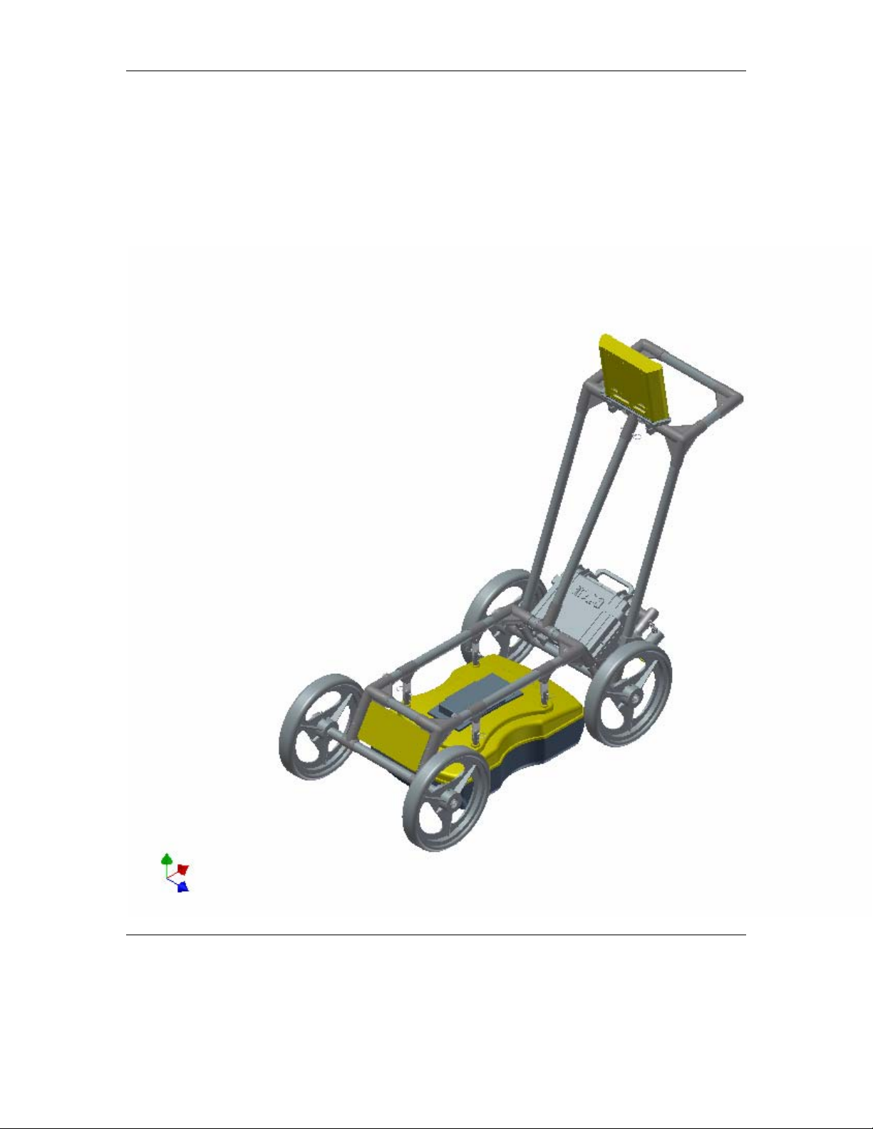
Smart Cart system and the Smart Handle system (see Figure 1-1).
The Smart Cart system consists of the cart structure, a Noggin, an odometer wheel, a
digital video logger (DVL), and a battery. Section 2 describes how to assemble a Smart
Cart system.
The Smart Handle system consists of the Smart Handle, a Noggin, an odometer wheel,
a digital video logger (DVL), and a battery. Section 3 describes how to assemble a
Smart Handle system.
Each Smart System’s DVL comes with all the necessary software installed. This includes
software to acquire data as well as software to replay data files. Data management
software allows the data to be transferred to an external computer for further processing
and/or plotting.
Figure 1-1: Noggin Smart Cart system (left) and Noggin Smart Handle System (right).
Smart Systems User’s Manual Version 1.1
2
2Assembling the Smart Cart
The Noggin Smart Cart can be configured for Noggin 250, Noggin 500 or Noggin 1000
operation. For the Noggin 250 Smart Cart, refer to Figure 2-10. For the Noggin 500
Smart Cart, refer to Figure 2-11 and for the Noggin 1000 Smart Cart, refer to Figure
2-12.
Figure 2-1: Fully assembled Smart Cart
Smart Systems User’s Manual Version 1.1
3
The Noggin Smart Cart comes fully assembled but in collapsed position (Figure 2-2).
The steps necessary to have a fully functioning system are:
Figure 2-2: Smart Cart in collapsed position.
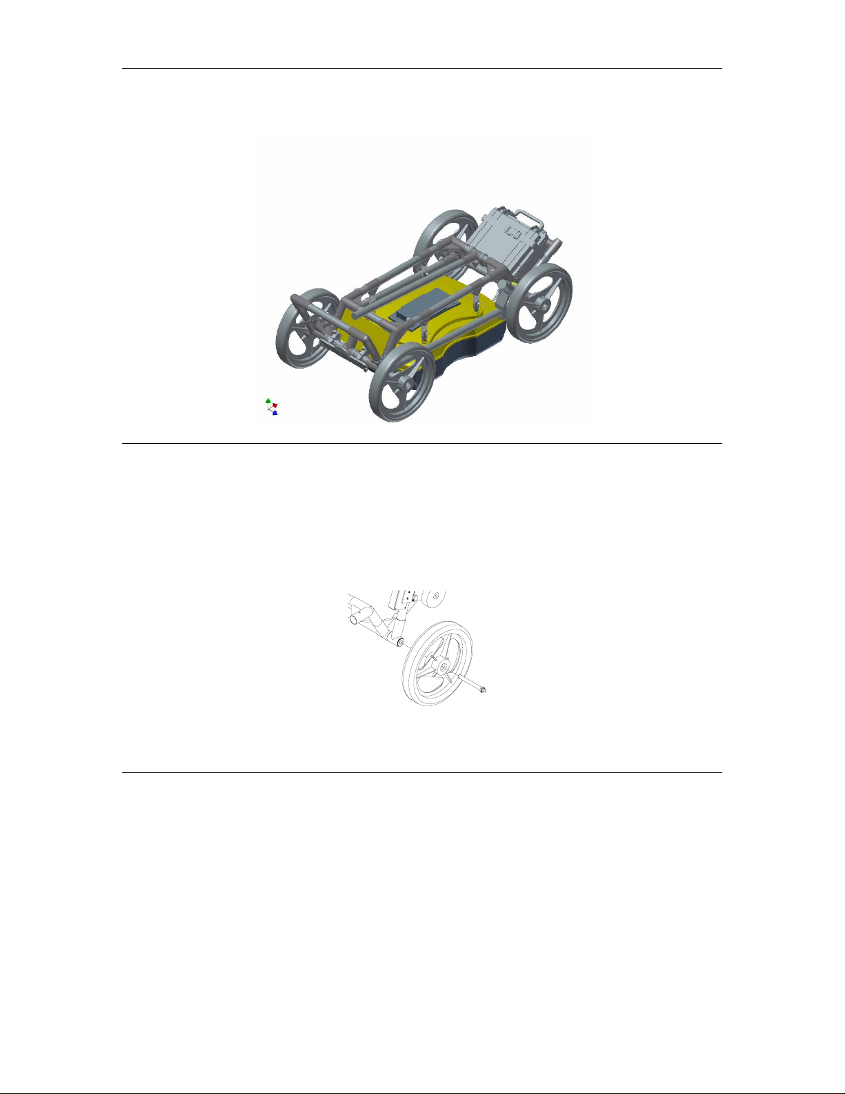
1. Attach wheels (if necessary): The Smart Cart may have been shipped without
the wheels attached or they may have been removed for storage. If this is the case, find
the axle for each wheel, press the button on the end of the axle, and insert the axle
through the wheel and into the cart frame. This is shown in Figure 2-3.
Figure 2-3: Attaching the wheel.
2. Unfold the Handle: Refer to Figure 2-4. Pull the ring to remove the handle
Clevis pin from the handle support arm. Raise the handle support arm and then the
handle and place the open end of the T-shaped tube on the handle onto the end of the
support arm (Step 1). Then lock the handle into position by lining up the hole in the
support arm with the hole in the T-shaped tube and inserting the handle Clevis pin (Step
2). (When folding the Smart Cart back up always ensure the handle folds down before
the handle support arm.)
With the system unfolded, make sure the small odometer wheel makes good contact
with the side of the cart wheel. If this contact is too loose, the odometer wheel may slip,
resulting in erroneous position measurements. If the odometer wheel seems loose, use

Smart Systems User’s Manual Version 1.1
4
a ¼ inch Allen (hexagonal) wrench to loosen the screws on the side of the odometer
(see Figure 2-10 or Figure 2-11) and pivot the entire odometer unit until the small
odometer wheel makes good contact with the side of the cart wheel. Then tighten the
screws to lock the odometer wheel in this position. After this has been done, it will be
necessary to re-calibrate the odometer (see Section 6.5.2).
Figure 2-4: Smart Cart set up.
3. Attach the Noggin: Before the Noggin unit can be attached to the Smart Cart,
the 4 swivel adapters (with attached Clevis pins) must be attached to the mounting posts
on the Noggin (see Figure 2-5). Set the swivel adapter down on the post. It may be
necessary to loosen the Allen (hexagonal) screw before the swivel adapter will slide
down into the proper position. This can be done using the 1/8” Allen (hexagonal) wrench
provided. Now, tighten each screw and then loosen ¼ turn so that the swivel adapters
are firmly attached to the post but can still rotate. DO NOT OVER-TIGHTEN!
Figure 2-5: Attaching the swivel adapters to the Noggin 250.

Smart Systems User’s Manual Version 1.1
5
Once all 4 swivel adapters are attached, the Noggin can then be attached to the Smart
Cart.
The Noggin is usually attached to the cart with the long axis of the Noggin unit parallel to
the wheels on the cart (see Figure 2-10 ,Figure 2-11 and Figure 2-12). For this
orientation, make sure the 37 socket female electrical receptacle on the Noggin faces
the back of the cart so that the cable on the cart will reach the receptacle.
It is also possible (but not usual) to attach the Noggin to the cart with the long axis of the
Noggin perpendicular (at right angles) to the wheels on the cart. For this orientation,
make sure the 37 socket female electrical receptacle on the Noggin is on the same side
of the cart as the odometer so that the cable on the cart will reach the receptacle.
Noggin 250: Remove the Clevis pins from the swivel adapters. Now, on the bottom of
the cart, locate the 4 oval, moveable hangers suspended from the frame of the cart (see
Figure 2-6). Notice that each hanger has a hole in it. To attach the Noggin 250 to the
cart, place each hanger into the slot on the top of the swivel adapters, line up the holes
and insert the Clevis pin.
Figure 2-6: Attaching the Noggin 250 to the cart.
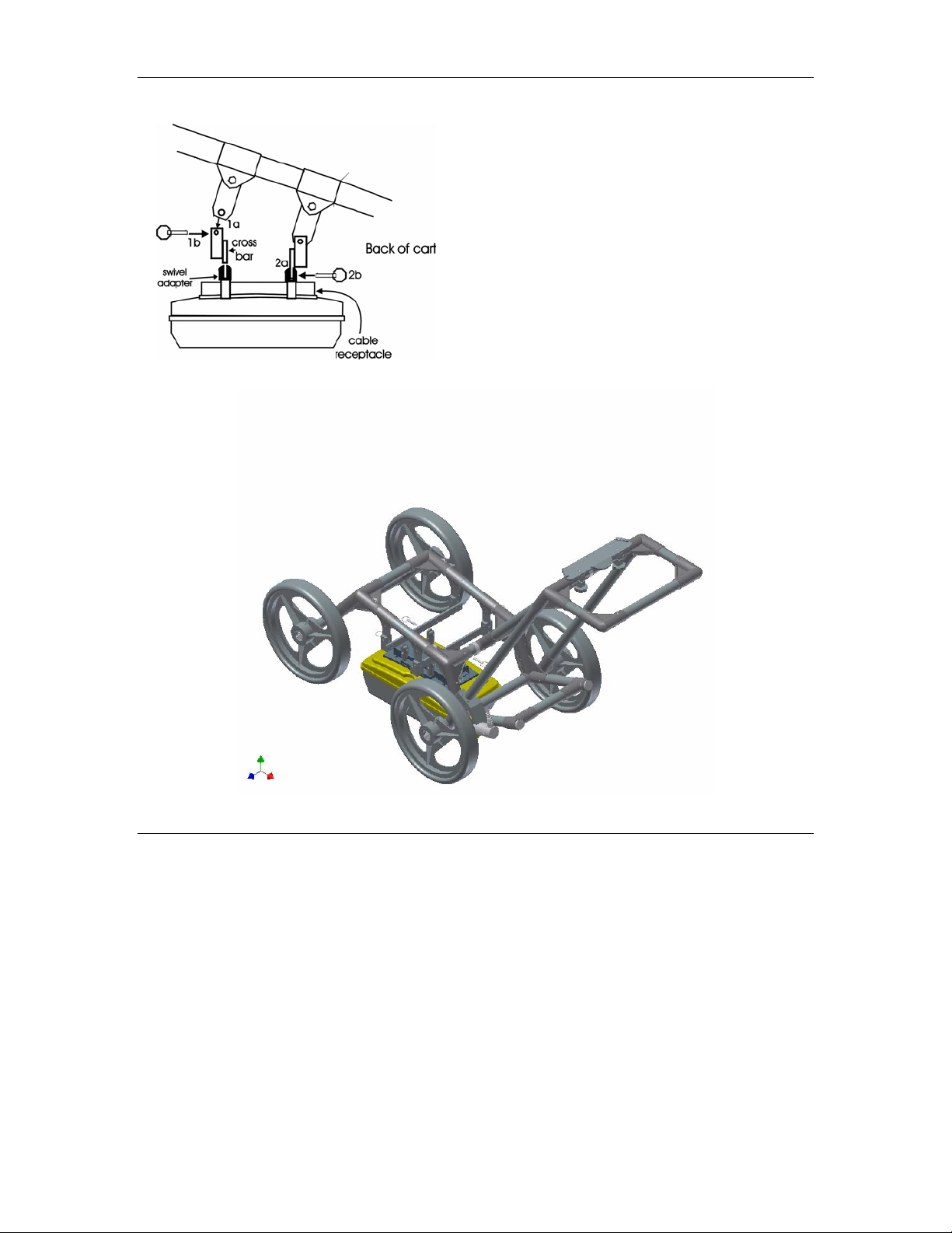
Noggin 500 and Noggin 1000: Remove the Clevis pins from the swivel adapters. Now,
on the bottom of the cart, locate the two, flat, moveable crossbars suspended from the
frame of the cart. If the crossbars are attached, go to step B.
Step A: If the crossbars are detached from the cart, they will need to be attached before
attaching the Noggin to the cart (see Figure 2-7 top). To attach the cross bars, use the 4
oval, moveable hangers suspended from the frame of the cart. Insert the hanger into the
slot on the crossbar, line up the holes and insert the Clevis pin.
Step B: Notice that each crossbar has 2 holes, one on each side. To attach the Noggin
500 to the cart, place the crossbars into the slots on the top of the swivel adapters, line
up the holes and insert the Clevis pins.
Smart Systems User’s Manual Version 1.1
6
Attach Cross bars to the cart (if
necessary).
a) Line up holes.
b) Insert Clevis pin.
Attach Noggin to cross bar.
a) Insert cross bar into swivel
adapter.
b) Insert Clevis pin.
Figure 2-7: Attaching the Noggin 500 and Noggin 1000 to the cart.
Connect the cable with the 37-pin male D connector to the Noggin and secure this
attachment by tightening the hand screws.
4. Attach the Digital Video Logger (DVL): The bottom of the Digital Video Logger
is designed to slide onto the support shelf attached to the Smart Cart (Figure 2-8). Line
up the bottom of the Digital Video Logger with the shelf and slide it back onto the shelf.
Push the Digital Video Logger back far enough so that the flexible clip on the front of the
shelf catches and holds the Digital Video Logger firmly in place. Wiggle the DVL to make
sure it is firmly snapped in before letting go of the unit. (To remove the Digital Video
Logger from the Smart Cart, this clip must be flexed downward as the DVL is slid
forward off of the shelf.
This manual suits for next models
4
Table of contents
Popular Radar manuals by other brands

Vega
Vega VEGAPULS 6X operating instructions

ABB
ABB LWT300 series user guide

Endress+Hauser
Endress+Hauser Micropilot M FMR250 operating instructions

SICK
SICK safeRS3 operating instructions

Endress+Hauser
Endress+Hauser levelflex M FMP 40 operating instructions

Bindicator
Bindicator F78MP Series Installation & operation manual


