Acconeer A111-003 User manual

A111-003 –Pulsed Coherent Radar
Operational description, User manual, and Installation instruction

A111-003 Pulsed Coherent Radar
Operational description, User manual, and Installation instruction
© 2021 Copyright by Acconeer 2022-01-04 Page 2 of 36
Features
•Fully integrated sensor
-60 GHz Pulsed Coherent Radar (PCR)
-Integrated Baseband, RF front-end and
Antenna in Package (AiP)
-5.5 x 5.2 x 0.88 mm fcCSP, 0.5 mm pitch
•Accurate distance ranging and movements
-Measures absolute range up to 2 m (1)
oAbsolute accuracy in mm
-Relative accuracy in µm
-Possible to recognize movement and
gestures for several objects
-Support continuous and single sweep
mode
-HPBW of 80 (H-plane) and 40 degrees
(E-plane) , possible to adapt beam pattern
using dielectric lens
•Easy integration
-One chip solution with integrated
Baseband and RF
-Can be integrated behind plastic or glass
without any need for a physical aperture
-Single reflowable component
-1.8 V single power supply, enable with
Power on Reset (PoR)
-Clock input for crystal or external
reference clock, 20-80 MHz
-SPI interface for data transfer, up to 50
MHz SPI clock support
-INTERRUPT support
A111-003 Overview
The A111-003 (hereafter referred to as A111) is a
radar system based on pulsed coherent radar
(PCR) technology and is setting a new
benchmark for power consumption and distance
accuracy –fully integrated in a small package of
29 mm2.
The A111 60 GHz radar system is optimized for
high precision and ultra-low power, delivered as a
one package solution with integrated Baseband,
RF front-end and Antenna in Package (AiP). This
will enable easy integration into any portable
battery driven device.
The A111 is based on leading-edge patented
sensor technology with pico-second time
resolution, capable of measuring absolute
distance with mm accuracy up to a range of
2 m (1) and with configurable update rate.
The A111 60 GHz radar remains uncompromised
by any natural source of interference, such as
noise, dust, color and direct or indirect light.
Applications
•High precision distance measurements with
mm accuracy and high update rate
•Ultra-low power consumption, e.g. average
power consumption 0.2 mW at 0.1 Hz update
rate, 3 mW at 10 Hz update rate and 20 mW
at 100 Hz update rate
•Proximity detection with high accuracy and
the possibility to define multiple proximity
zones
•Motion detection, Speed detection
•Enables material detection
•High precision object tracking, enabling
gesture control
•High precision tracking of 3D objects
•Monitor vital life signs such as breathing and
pulse rate
•Only for factory installation in the interior of
new passenger motor vehicles
(1) 2m ranging is guaranteed for an object size, shape and dielectric properties corresponding to a spherical corner reflector of 5 cm radius.

A111-003 Pulsed Coherent Radar
Operational description and User manual
Page 3 of 36 2022-01-04 © 2021 Copyright by Acconeer
Table of Contents
1Revision History............................................................................................................................ 4
2Description..................................................................................................................................... 5
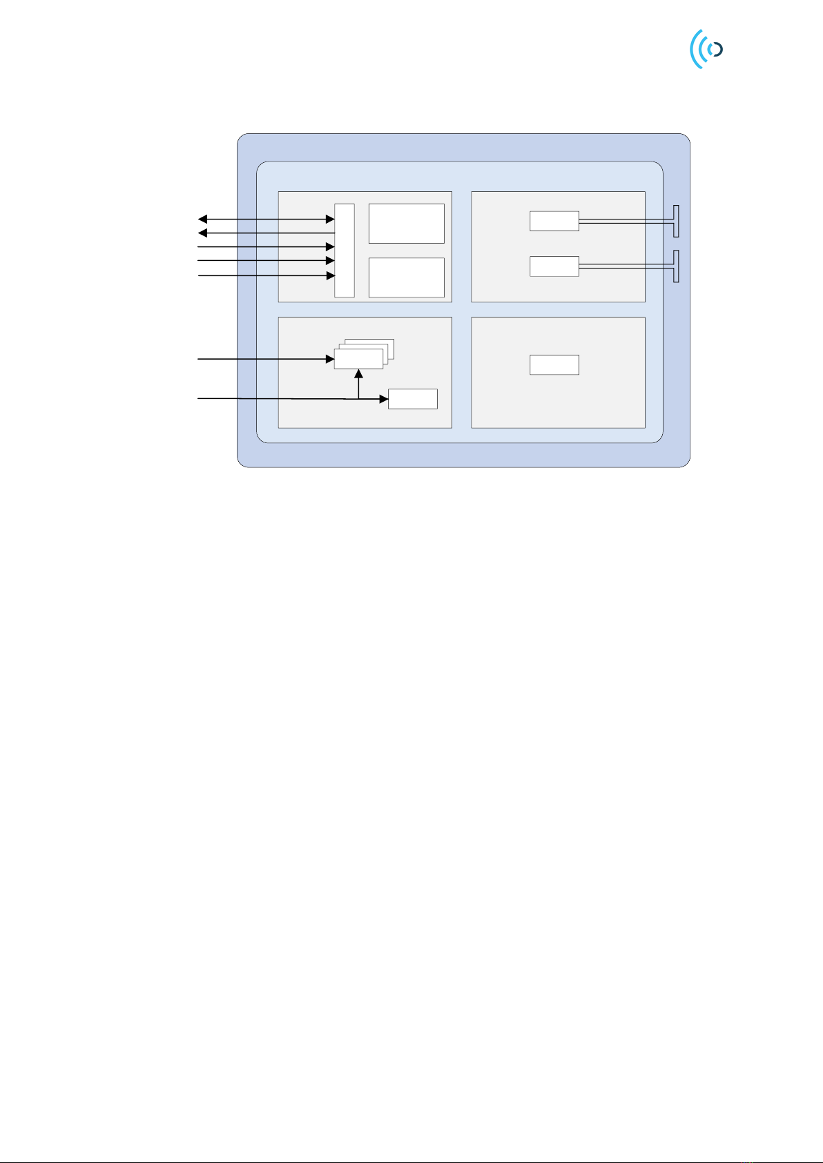
2.1 Functional Block Diagram ................................................................................................... 6
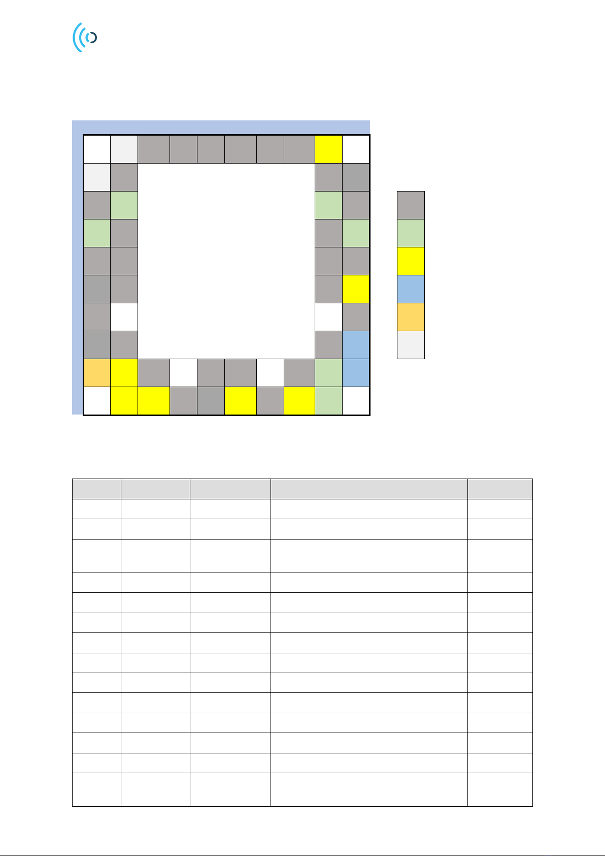
3Pin Configuration and Functions................................................................................................ 7
4Specifications................................................................................................................................ 9
4.1 Absolute Maximum Ratings ................................................................................................ 9
4.2 Environmental Sensitivity .................................................................................................... 9
4.3 Recommended Operating Conditions............................................................................. 10
4.4 Electrical Specification....................................................................................................... 10
4.5 Power Consumption Summary......................................................................................... 11
5Timing Requirements................................................................................................................. 13
5.1 Serial Peripheral Interface................................................................................................. 13
6Typical Characteristics............................................................................................................... 15
6.1 Radar Loop Gain Pattern................................................................................................... 15
6.2 Relative Phase Accuracy................................................................................................... 16
7Functional Description ............................................................................................................... 17
7.1 Acconeer Software............................................................................................................. 18
7.2 Software Integration........................................................................................................... 18
7.3 Power Sequences............................................................................................................... 19
8Layout Recommendations......................................................................................................... 22
8.1 Bill of Material (BoM).......................................................................................................... 23
8.2 XTAL..................................................................................................................................... 24
8.3 External Clock Source ....................................................................................................... 25
8.4 Power Supply...................................................................................................................... 26
9Regulatory Approval................................................................................................................... 28
9.1 ETSI...................................................................................................................................... 28
9.1.1 EU type examination certificate.................................................................................... 28
9.2 Declaration of conformity FCC ......................................................................................... 29
9.2.1 Host integrator instructions ........................................................................................... 30
10 Mechanical Data..................................................................................................................... 32
10.1 Moisture Sensitivity Level and Recommended Reflow Profile.................................... 34
10.2 RoHS and REACH Statement.......................................................................................... 34
11 Abbreviations........................................................................................................................... 35
Disclaimer............................................................................................................................................ 36

A111-003 Pulsed Coherent Radar
Operational description, User manual, and Installation instruction
© 2021 Copyright by Acconeer 2022-01-04 Page 4 of 36
1 Revision History
Revision
Comment
V1.0
Released version

A111-003 Pulsed Coherent Radar
Operational description and User manual
Page 5 of 36 2022-01-04 © 2021 Copyright by Acconeer
2 Description
The A111-003 (hereafter referred to as A111) is an optimized low-power, high-precision, 60 GHz
radar sensor with integrated Baseband, an RF front-end and an Antenna in Package (AIP).
The sensor is based on pulsed coherent radar (PCR) technology, featuring a leading-edge patented
solution with picosecond time resolution. The A111 is the perfect choice for implementing high-
accuracy, high-resolution sensing systems with low-power consumption.
Ordering information
Part number
Package
Size (nom)
Primary component container
A111-003-T&R
fcCSP50
5.2 x 5.5 x 0.88 mm
Tape & reel
A111-003-TY
fcCSP50
5.2 x 5.5 x 0.88 mm
13” Tray
Acconeer A111 marking

A111-003 Pulsed Coherent Radar
Operational description, User manual, and Installation instruction
© 2021 Copyright by Acconeer 2022-01-04 Page 6 of 36
2.1 Functional Block Diagram
A111 One Package Solution
A111 Silicon
TX
RX
PLL
LDOs
PoR
Communication
Program
memory
Data
memory
SPI (4)
INTERRUPT
XIN (ref clk)
XOUT
1.8V Single
power supply
ENABLE
Digital
Power Timing
mmWave Radio Tx ant.
Rx ant.
CTRL (optional)
Figure 2.1. The A111 functional block diagram.
The A111 silicon is divided into four functional blocks: Power, Digital, Timing and mmWave radio.
The Power functional block includes LDOs and a Power on Reset (PoR) block. Each LDO creates its
own voltage domain. The PoR block generates a Reset signal on each power-up cycle. The host
interfaces the Power functional block of the sensor via 1.8V Single power supply and ENABLE.
The Digital functional block includes sensor control. The data memory stores the radar sweep data
from the ADC. The host interfaces the Sensor via an SPI interface, a Clock (XIN, XOUT),
INTERRUPT signal and optional CTRL signal.
The Timing block includes the timing circuitry. The PLL digital clock output is used to drive digital
logic and is synthesized from external crystal (XIN/XOUT) or external reference frequency (XIN ref
clk). The operational oscillator (XIN) frequency range is 20-80 MHz.
The mmWave radio functional block generates and receives radar pulses and includes transmitter
(TX), receiver (RX) and interfaces toward the integrated antennas. The A111 operates in the 57-64
GHz band.

A111-003 Pulsed Coherent Radar
Operational description and User manual
Page 7 of 36 2022-01-04 © 2021 Copyright by Acconeer
3 Pin Configuration and Functions
The below figure shows the A111 pin configuration, top view:
1
2
3
4
5
6
7
8
9
10
A
NC
CTRL
B
NC
C
VIO_1a
VIO_2a
GND
D
VIO_1b
VIO_2b
Supply
E
I/O
F
ENABLE
CLK
G
Analog
H
XOUT
NC
J
VBIAS
SPI_SS
VIO_3a
XIN
K
SPI_CLK
SPI_MISO
SPI_MOSI
INTERRUPT
VIO_3b
Figure 3.1. Pin configuration of the A111 sensor, top view.
The below table shows the A111 total number of 50 pins:
Pin
Pin name
Pin type
Description
Comment
A2
NC
Must no connect
A3-A8
GND
Ground
Must be connected to solid ground plane
A9
CTRL
I/O
Optional control signal. Must be
connected to either host MCU or ground
optional
B1
NC
Must no connect
B2, B9
GND
Ground
Must be connected to solid ground plane
B10
GND
Ground
Must be connected to solid ground plane
C1
GND
Ground
Must be connected to solid ground plane
C2
VIO_1a
Supply voltage
Supply voltage, RF part (1)
C9
VIO_2a
Supply voltage
Supply voltage, RF part (1)
C10
GND
Ground
Must be connected to solid ground plane
D1
VIO_1b
Supply voltage
Supply voltage, RF part (1)
D2, D9
GND
Ground
Must be connected to solid ground plane
D10
VIO_2b
Supply voltage
Supply voltage, RF part (1)
E1, E2,
E9, E10
GND
Ground
Must be connected to solid ground plane

A111-003 Pulsed Coherent Radar
Operational description, User manual, and Installation instruction
© 2021 Copyright by Acconeer 2022-01-04 Page 8 of 36
Pin
Pin name
Pin type
Description
Comment
F1
GND
Ground
Must be connected to solid ground plane
F2, F9
GND
Ground
Must be connected to solid ground plane
F10
ENABLE
I/O
Must be connected to host MCU
available GPIO. ENABLE is active high
G1,
G10
GND
Ground
Must be connected to solid ground plane
H1
GND
Ground
Must be connected to solid ground plane
H2, H9
GND
Ground
Must be connected to solid ground plane
H10
XOUT
CLK
XTAL out
No connect
if no XTAL
J1
VBIAS
Analog
The analog VBIAS must be connected to
VIO_3
J2
SPI_SS
I/O
SPI slave select, active low select.
J3, J5,
J6, J8
GND
Ground
Must be connected to solid ground plane
J9
VIO_3a
Supply voltage
Supply voltage, digital part (1)
J10
XIN
CLK
XTAL input OR external ref clk input
1.1V
domain
K2
SPI_CLK
I/O
SPI Serial Clock
K3
SPI_MISO
I/O
Master Input –Slave Output
K4
GND
Ground
Must be connected to solid ground plane
K5
GND
Ground
Must be connected to solid ground plane
K6
SPI_MOSI
I/O
Master Output –Slave Input
K7
GND
Ground
Must be connected to solid ground plane
K8
INTERRUPT
I/O
Interrupt signal, that is used as an
interrupt in the host, more details are
found in section 7, Description.
mandatory
K9
VIO_3b
Supply voltage
Supply voltage, digital part (1)
Table 3.1. A111 sensor pin list
(1) VIO_1a and VIO_1b are short circuit inside the sensor. VIO_2a and VIO_2b are short circuit inside the sensor. VIO_3a
and VIO_3b are short circuit inside the sensor.

A111-003 Pulsed Coherent Radar
Operational description and User manual
Page 9 of 36 2022-01-04 © 2021 Copyright by Acconeer
4 Specifications
4.1 Absolute Maximum Ratings
The below table shows the A111 absolute maximum ratings over operating temperature range, on
package, unless otherwise noted:
Parameter
Description
Min.
Max.
Unit
VIO_1 (2)
1.8 V RF power supply
0
2.0
V
VIO_2 (2)
1.8 V RF power supply
0
2.0
V
VIO_3
1.8 V digital power supply
0
2.0
V
XIN (1)
Clock input port for crystal or reference
clock
-0.5
1.6
V
I/O
I/O supply voltage
-0.5
VIO_3+0.5
V
TOP
Operating temperature range
-40
85
°C
TSTG
High temperature storage
150
°C
Table 4.1. Absolute maximum ratings
(1) XIN input may not exceed 0V when ENABLE is low.
(2) VIO_1 and VIO_2 must never exceed VIO_3.
Stresses beyond those listed in table 4.1 may cause permanent damage to the device. These are stress
ratings only and functional operation of the device at these conditions or at any other conditions
beyond those indicated under Recommended Operating Conditions is not implied. Exposure to
absolute-maximum-rated conditions for extended periods of time may affect device reliability.
4.2 Environmental Sensitivity
The below table shows the A111 environmental sensitivity:
Parameter
Standard
Max.
Unit
Storage temperature
JESD22-A103 (1)
150(1)
ºC
Reflow soldering temperature (1)
J-STD-020 (1)
260
ºC
Moisture Sensitivity Level
JESD22-A113 (1)
MSL3
ESD, Charge Device Model (CDM)
JS-002, Class C2
500
V
ESD, Human Body Model (HBM)
JS-001, Class 1C
1000
V
Latch-up
JESD78, Class I
Pass
Table 4.2 Environmental sensitivity
(1) For reference only. The package is generically qualified by the manufacturer. Acconeer does not guarantee adherence to
standard.

A111-003 Pulsed Coherent Radar
Operational description, User manual, and Installation instruction
© 2021 Copyright by Acconeer 2022-01-04 Page 10 of 36
4.3 Recommended Operating Conditions
The below table shows the A111 recommended operating conditions, on package:
Parameter
Min.
Typ.
Max.
Unit
Operating power supply voltage, VIO_1
1.71
1.8
1.89
V
Operating power supply voltage, VIO_2
1.71
1.8
1.89
V
Operating power supply voltage, VIO_3
1.71
1.8
1.89
V
I/O operating range
-0.3
VIO_3+0.3
V
XIN operating range (1)
-0.3
1.2
V
Operating temperature (Top)
-40
85
ºC
Table 4.3. Recommended operating conditions
(1) XIN input must not exceed 0V when ENABLE is low.
4.4 Electrical Specification
The below table shows the A111 electrical DC specification conditions, on package, Top = -40ºC to
85ºC:
Parameter
Min.
Typ.
Max.
Unit
Current into any power supply
0
100
mA
I/O VIL Low-level input voltage
-0.3
0.10*VIO_3
V
I/O VIH High-level input voltage
0.90*VIO_3
VIO_3+0.3
V
I/O VOL Low-level output voltage
0
0.4
V
I/O VOH High-level output voltage
1.6
VIO_3
V
I/O IOL (VOL = 0.4V)
4.56
7.8
12.4
mA
I/O IOH (VOH = VIO_3-0.4)
3.42
5.8
9.16
mA
I/O IIL Low-level input current
<1
µA
I/O IIH High-level input current
<1
µA
XIN VIL Low-level input voltage
-0.3
0.4
V
XIN VIH High-level input voltage
1.0
1.2
V
XIN IIL Low-level input current
<1
µA
XIN IIH High-level input current
<1
µA
Table 4.4. Electrical DC conditions

A111-003 Pulsed Coherent Radar
Operational description and User manual
Page 11 of 36 2022-01-04 © 2021 Copyright by Acconeer
The below table shows the A111 electrical AC specification conditions, on package, at Top = -40ºC to
85ºC:
Parameter
Min.
Typ.
Max.
Unit
I/O output operating frequency(2)
0
100
MHz
I/O minimum positive and negative pulse
6.25
ns
XIN operating frequency
20
80(1)
MHz
Table 4.5 Electrical AC conditions
(1) The maximum external reference clock frequency is 80 MHz and the maximum XTAL frequency is 50 MHz.
(2) Load capacitance 2 pF.
4.5 Power Consumption Summary
Table 4.6 summarizes the steady-state current consumption for the sensor states, average current
ratings at all power terminals (VIO_1, VIO_2, VIO_3), VIO 1.8 V, at Top = -40ºC to 85ºC:
Parameter
Typ.
Max.
Unit
OFF
VIO_1
29
139
µA
OFF
VIO_2
31
158
µA
OFF
VIO_3
0
23
µA
HIBERNATE
VIO_1
29
139
µA
HIBERNATE
VIO_2
31
158
µA
HIBERNATE
VIO_3
410
2064
µA
SLEEP
VIO_1
764
1069
µA
SLEEP
VIO_2
767
1082
µA
SLEEP
VIO_3
1.59
3.48
mA
READY
VIO_1
1.32
1.90
mA
READY
VIO_2
768
1085
µA
READY
VIO_3
31.0
41.6
mA
ACTIVE
VIO_1
2.85
4.00
mA
ACTIVE
VIO_2
1.34
1.91
mA
ACTIVE
VIO_3
60.8
79.9
mA
MEASURE, PROFILE 1
VIO_1
3.94
5.32
mA
MEASURE, PROFILE 1
VIO_2
2.31
3.08
mA
MEASURE, PROFILE 1
VIO_3
61.8
81.1
mA
MEASURE, PROFILE 2
VIO_1
4.01
5.40
mA
MEASURE, PROFILE 2
VIO_2
2.37
3.16
mA
MEASURE, PROFILE 2
VIO_3
61.8
81.1
mA
MEASURE, PROFILE 3
VIO_1
4.30
5.76
mA
MEASURE, PROFILE 3
VIO_2
2.80
3.67
mA
MEASURE, PROFILE 3
VIO_3
62.4
81.8
mA

A111-003 Pulsed Coherent Radar
Operational description, User manual, and Installation instruction
© 2021 Copyright by Acconeer 2022-01-04 Page 12 of 36
MEASURE, PROFILE 4
VIO_1
5.20
6.86
mA
MEASURE, PROFILE 4
VIO_2
4.18
5.32
mA
MEASURE, PROFILE 4
VIO_3
62.4
81.8
mA
MEASURE, PROFILE 5
VIO_1
6.37
8.29
mA
MEASURE, PROFILE 5
VIO_2
6.06
7.61
mA
MEASURE, PROFILE 5
VIO_3
62.4
81.7
mA
Table 4.6. Average current ratings at power terminals for the sensor states.

A111-003 Pulsed Coherent Radar
Operational description and User manual
Page 13 of 36 2022-01-04 © 2021 Copyright by Acconeer
5 Timing Requirements
5.1 Serial Peripheral Interface
The Serial Peripheral Interface (SPI) is a 4-wire serial bus, used for configuration and reading output
from the A111 radar sensor. The A111 radar sensor is an SPI slave device connected to the SPI
master, as described in figure 5.1. The A111 allows several devices to be connected on the same SPI
bus, with a dedicated slave-select signal. Daisy-chain is not supported.
Host
(SPI Master) A111
(SPI Slave)
A111
(SPI Slave)
SPI_CLK
SPI_MOSI
SPI_SS1
SPI_SS2
SPI_MISO
Figure 5.1. SPI master-slave connection
The serial data transfer input (MOSI) and output (MISO) to the A111 are synchronized by the
SPI_CLK. The Slave Select signal (SS) must be low before and during transactions. The MOSI is
always read on the rising edge of SCLK and the MISO changes value on the falling edge of SPI_CLK
(SPI mode 0, CPOL/CPHA = 0). SS requires release in between transactions. See figure 5.2 and table
5.1 for timing characteristics.
SPI_ClK
MOSI
MISO
SS
SS setup time
MSB
MOSI hold time MOSI setup time MISO propagation delay SS hold time
LSB
15
15 14
14
13
13
0
0
1
1
2
2
Figure 5.2: Timing diagram of SPI, CPOL=0 and CPHA=0.

A111-003 Pulsed Coherent Radar
Operational description, User manual, and Installation instruction
© 2021 Copyright by Acconeer 2022-01-04 Page 14 of 36
Parameter
Min.
Typ.
Max.
Unit
Clock frequency (1)
50
MHz
SS setup time
1.0
ns
SS hold time
2.0
ns
MOSI setup time
1.0
ns
MOSI hold time
2.5
ns
MISO propagation delay (2)
5.5
ns
Table 5.1 SPI timing characteristics
(1) The 50 MHz clock frequency requires that the reference clock is at least 20.625 MHz
(2) 10pF load on SPI_MISO

A111-003 Pulsed Coherent Radar
Operational description and User manual
Page 15 of 36 2022-01-04 © 2021 Copyright by Acconeer
6 Typical Characteristics
6.1 Radar Loop Gain Pattern
The Radar Loop Gain pattern includes the gain in both the TX and RX radar path and is defined as the
angular separation between the two points at which the gain has decreased by 3dB relative to the
maximum main lobe value, when the radar itself is used to measure the reflected power. For details
regarding the measurement setup, refer to “Hardware and physical integration guideline”, chapter 1.2.
Conditions: TA= 25 ºC, VDD = 1.8 V. Tested on 5 XR112 devices.
The below figure shows the Radar Loop Gain Radiation Pattern normalized to Free Space Sensor
Boresight at Elevation plane (E-plane).
Figure 6.1. Normalized radar loop gain radiation pattern at E-plane.
The below figure shows the Radar Loop Gain Radiation Pattern normalized to Free Space Sensor
Boresight at Horizontal plane (H-plane).

A111-003 Pulsed Coherent Radar
Operational description, User manual, and Installation instruction
© 2021 Copyright by Acconeer 2022-01-04 Page 16 of 36
Figure 6.2. Normalized radar loop gain radiation pattern at H-plane
6.2 Relative Phase Accuracy
Conditions: TA= 25 ºC, VDD = 1.8 V. Statistical result based on sweep count 100, 20 tested devices.
Standard deviation of phase estimation, measured at a distance of 0.35 m. Object metal cylinder, 40
mm in diameter.
Average STD of relative phase estimation:
6.1 degrees in relative phase accuracy, translates to 42 µm in relative distance accuracy.

A111-003 Pulsed Coherent Radar
Operational description and User manual
Page 17 of 36 2022-01-04 © 2021 Copyright by Acconeer
7 Functional Description
The below figure shows the A111 system integration with Host MCU:
Host MCU A111
Sensor
TCXO
ENABLE x1
SPI x4
INTERRUPT x1
1.8V single power supply
CLK ref. 20-80 MHz
CTRL x1(optional)
Figure 7.1. System integration
The Acconeer software is executed on Host MCU that handles sensor initiation, configuration, sweep
acquisition and signal processing.
The Serial Peripheral Interface (SPI) is a 4-wire serial bus, used for configuration and reading output
from the A111 radar sensor. The A111 radar sensor is an SPI slave device, connected to the SPI
master (Host MCU), and allows several devices to be connected on same SPI bus, with a dedicated
slave-select signal. Daisy-chain is not supported.
The sensor provides support for ENABLE and INTERRUPT as interrupt signal, always output, that is
used as an interrupt in the Host MCU. The sensor supports an optional control signal: CTRL, which is
configured through software, e.g. for controlling the operating state of the sensor to idle in Hibernate.

A111-003 Pulsed Coherent Radar
Operational description, User manual, and Installation instruction
© 2021 Copyright by Acconeer 2022-01-04 Page 18 of 36
7.1 Acconeer Software
The Acconeer software has been written in C and is portable to any OS and HW platform. The
Acconeer software is executed on Host MCU and delivered as binaries, except for integration software
that is delivered as source code.
The below figure shows the A111 software offer.
Figure 7.2. Acconeer Software offer
The RSS (Radar System Software) provides output at two different levels, Service and Detector. RSS
provides an API (Application Programming Interface) for Application utilization of various Services
and Detectors.
The Service output is pre-processed sensor data as a function of distance E.g. Envelope data
(amplitude of sensor data), Power bin data (integrated amplitude data in pre-defined range intervals),
IQ modulated data (representation in cartesian) etc.
Detectors are built on Service data as input and the output is a result E.g. Distance detector that
presents distance and amplitude result based on envelope Service etc.
Customer can either use Acconeer detector or develop their own signal processing based on Service
data.
Acconeer provides several example applications to support customer own application development.
Also, customer guidelines are provided for application development utilizing the Acconeer RSS API.
Acconeer provides several reference drivers as source code, e.g. Support for Cortex M4, Cortex M7
MCU’s.
7.2 Software Integration
Integration software shall implement functions defined in a definitions file provided in Acconeer
Software offer. This includes handling of SPI, ENABLE, INTERRUPT and CTRL, as well as
potential OS functions.
See reference HAL - User Guide for guideline on software integration and HAL implementation
(https://www.acconeer.com/products).

A111-003 Pulsed Coherent Radar
Operational description and User manual
Page 19 of 36 2022-01-04 © 2021 Copyright by Acconeer
7.3 Power Sequences
The power-up sequence is described using the recommended integration shown in the below figure:
A111
INTERRUPT
SPI_SS
SPI_MISO
SPI_MOSI
SPI_CLK
ENABLE
VIO_1a,b
VIO_2a,b
VIO_3a,b
VBIAS
XIN
XOUT
GNDs
1.8V
X1
C5C4
R1
C1
C2
C3
Host
CTRL
R2
Figure 7.3. Recommended integration of the A111 radar sensor.
The power up sequence is shown in below figure.

A111-003 Pulsed Coherent Radar
Operational description, User manual, and Installation instruction
© 2021 Copyright by Acconeer 2022-01-04 Page 20 of 36
Figure 7.4. Power up sequence
The power up sequence is initiated by turning on VIO_3a,b. It must be turned on before or
simultaneously with ENABLE and VIO_1-2a,b. ENABLE and VIO_1-2a,b can be turned on in any
order and independently of each other. A111 should however not be considered as in state “ON” until
all supply voltage levels are stable and ENABLE is high. The time constant t1in figure 7.4 denotes
this time. The actual value of t1depends on the power supply and the decoupling capacitors used. If
the CTRL signal is used, it must be held at 0V during time t1.
Next step in the power up sequence is to have a settling time for the XTAL oscillator to stabilize,
shown as time t2in figure 7.4. This may take up to several milliseconds depending on the XTAL
performance. The sensor does not require any settling time if it is integrated using an external
reference clock. It is advised to have the clock inactive at 0 V while ENABLE is inactive.
Now the A111 radar sensor is ready for SPI communication.
Time
VIO_3a,b
ENABLE
t1t2
XIN
VIO_1-2a,b
CTRL
This manual suits for next models
3
Table of contents
Other Acconeer Radar manuals
Popular Radar manuals by other brands

Decatur Electronics
Decatur Electronics SI-3C user manual

Guideline Geo
Guideline Geo MALA MIRAsoft HDR user guide

Traffic Logix
Traffic Logix SafePace 650 installation manual

MPH Industries
MPH Industries ai.951689 installation guide

JRC
JRC JMA-3300 Series installation manual

HIK VISION
HIK VISION DS-TDSB00-EKT manual

Blackbe;rry
Blackbe;rry Radar R2 installation guide

Micran
Micran MRS-1000 installation manual

Ohmart Vega
Ohmart Vega VEGAPULS 67 Product information

Endress+Hauser
Endress+Hauser FOUNDATION Fieldbus Micropilot FMR56 Brief operating instructions

Honeywell
Honeywell SmartLine SLG 700 quick start guide

Valentine One
Valentine One Generation 2 quick start guide