NoiseKen THA-380M60G User manual

INSTRUCTION MANUAL
TEM horn antenna
MODEL
THA-380M60G
NOISE LABORATORY CO., LTD.
Edition 1.01
AEY00105-00E-0

NOTICE
•
The contents of this instruction manual (the “Manual”) are subject to change without prior
notice.
•
No part of the Manual may be reproduced or distributed, in any form or by any means,
without the authori ation of Noise Laboratory Co., Ltd. (the “Company”).
•
The contents of the Manual have been thoroughly examined. However, if you find any
problems, misprints, or missing information, please feel free to contact our sales agent
who you purchased our product from.
•
The Company assumes no responsibility for any loss or damage resulting from improper
usage, failure to follow the Manual, or any repair or modifications of this product
undertaken by a third party other than the Company or the agent authori ed by the
Company.
•
The Company assumes no responsibility for any loss or damage resulting from
remodeling or conversion solely undertaken by the user.
•
Please note that the Company cannot be held responsible for any consequences arising
from the use of this product.

1
The instrument may only be used by trained EMC technicians
(electrical technicians)
Failure to follow this rule risks death or serious injury.
The instrument may not be used by people fitted with
electronic medical devices such as pacemakers and such
people may not enter the testin site while the instrument is
operatin
The medical device may malfunction since the instrument emits more
electromagnetic wave than the regulated value.
To prevent people from bein exposed to radio waves, use the
product accordin to the protection uidelines defined by
ICNIRP.
Do not hold the product directly with your hands.
Do not use the instrument for any purposes other than the
EMC testin purposes described in this instruction manual
.
The instrument is not supposed to be used in manufacturing process of a
factory.
Take an appropriate measure, such as installing the product in
anechoic chamber or shielded room, against electromagnetic noise.
The instrument may not be used in a location where fire is
prohibited or there is a risk of explosion
1. IMPORTANT SAFETY PRECAUTIONS
The "Important Safety Precautions" explain rules that must be followed to prevent any risk of
harm or injury to the user of the instrument or to other people.
Before setting up the test site, connecting the equipment, or
starting testing, please read the Chapter entitled "Basic Safety
Precautions for the Safe Use of the Simulator" which contains
additional safety advice.
※When usin the product, follow the re ulations on radio waves in your country/area.

Memorandum
2
3
2. APPLICATION FORM FOR INSTRUCTION MANUAL
To: Noise Laboratory Co., Ltd. via sales agent
We place an order for an instruction manual.
Model Name
THA-380M60G
Serial No.
Applicant Address
Cut Line
Company Name
Department
Contact Person
Phone No.
FAX No.
Cut off this page "PURCHASE ORDER FOR
INSTRUCTION MANUAL" from this volume and
keep it for
future use with care.
When an INSTRUCTION MANUAL is required, fill in the above Application
Form and mail or fax it to your nearest sales agent of Noise Laboratory or Noise
Laboratory.
Cut Line
The address, company name, individual's name, and other personal information
(henceforth referred to as "personal information") entered in the application
form will only be used for the purpose of sending the Instruction
Manual and will
not be shown or passed to any third party without a valid reason.
Noise Laboratory Co., Ltd. will manage customer's personal information in an
appropriate manner.

Memorandum
4

5
3. TABLE OF CONTENTS
1. IMPORTA T SAFETY PRECAUTIO S ..................................................................................... 1
2. APPLICATIO FORM FOR I STRUCTIO MA UAL ............................................................ 3
3. TABLE OF CO TE TS ............................................................................................................... 5
4. I TRODUCTIO ......................................................................................................................... 6
5. BASIC SAFETY PRECAUTIO S ................................................................................................ 7
Safety Warning Signs and Their Meanings ............................................................................................ 7
Basic Safety Precautions ........................................................................................................................ 7
6. PRODUCT COMPO E TS ......................................................................................................... 9
7. APPEARA CE A D FU CTIO OF EACH PART ................................................................. 10
7-1. Appearance of the Main Unit .................................................................................................. 10
7-2. Antenna rear panel .................................................................................................................... 10
8. OPERATIO ............................................................................................................................... 11
9. CHARACTERISTIC DATA ......................................................................................................... 12
9-1. VSWR (typ.) .............................................................................................................................. 12
9-2. Input Power for 300V/m at 0.1m (typ.) ................................................................................... 12
9-3. Electric field distribution characteristics at 0.1m (typical) .................................................. 13
9-4. Antenna Radiation Pattern (typ.) ........................................................................................... 15
9-5. Antenna Gain (typ.) ................................................................................................................. 22
10. SPECIFICATIO S .................................................................................................................. 23
11. WARRA TY ............................................................................................................................ 24
12. MAI TE A CE ..................................................................................................................... 26
13. CO TACTI G TECH ICAL SUPPORT ............................................................................... 27

6
4. INTRODUCTION
We thank you very much for your purchase of the TEM horn antenna Model:
THA-380M60G. It is recommended that the contents of this manual be thoroughly
understood and used as a ready reference for operation.
This Instruction Manual was prepared so that any person who can observe the prescribed
instruction method and operating precautions may safely handle and fully utili e this
THA-380M60G.
Keep this Instruction Manual by your side or other proper location so that it may be readily available
when using the THA-380M60G.
The product accepts the following maximum input power in each of the frequency ranges shown
below.
380 MH ~ 750 MH ・・・・ 180 W MAX
750 MH ~ 1.7 GH ・・・・ 100 W MAX
1.7 GH ~ 6.0 GH ・・・・ 65 W MAX
§Features
①:THA-380M60G is conforming to IEC 61000-4-39 Ed.1.
②:Wide frequency range from 380 MH to 6.0 GH .
③:It has a wide electric field uniform property, and the maximum point of the near electric field
distribution at each frequency is at the center.
This product has been commerciali ed through joint research with the National Institute of
Information and Communications Technology (NICT).
This product uses the intellectual property rights of NICT.
7
5. BASIC SAFETY PRECAUTIONS
Safety Warning Signs and Their Meanings
Indicates Warnin .
Failure to follow this safety information can lead to a
potentially hazardous situation resulting in death or
serious injury.
Indicates Caution.
Failure to follow this safety information can lead to a
potentially hazardous situation resulting in a minor
injury or moderate dama e.
Basic Safety Precautions
1. Do not use this unit in areas where open flames are prohibited or areas having an explosive atmosphere.
Electrical discharges can occur during use, which can cause these atmospheres to ignite. (Precaution
regarding personal safety and environment)
2. Do not allow people with pacemakers or other electronic medical devices to operate this unit and to enter
the testing area while this unit is operating. Failure to observe this can result in malfunctions in the
electronic medical device and endanger personal safety. (Precaution regarding personal safety and
operation)
3. To prevent people from being exposed to radio waves, use the product according to the protection
guidelines defined by ICNIRP. Do not hold the product directly with your hands. (Precaution regarding
personal safety, operation, and environment)
4. Noise Laboratory and our affiliated dealers are not liable for any injuries or equipment damage due to
improper operation of this unit or for any resulting incidental damages. (Precaution regarding personal
safety, operation, environment, and connection)
5. When operating this unit, do not leave the equipment unmonitored. Before leaving this unit, be sure to turn off
test equipment power and terminate testing.
If you fail to observe this, you could endanger people in the surrounding area and testing equipment.
(Precaution regarding personal safety, operation, and environment)
6. Do not use or store in environments with extremely hot or cold temperatures. If you cannot maintain a
suitable operating environment (temperature: 15°C to 35°C, humidity: 25% to 75%), the unit can be
damaged and result in impaired performance. (Precaution regarding environment)
7. In the event that condensation forms, be sure that the unit is fully dried before starting operation. Failure to
observe this can damage the unit and result in impaired performance. (Precaution regarding environment)

BASIC SAFETY PRECAUTIONS
8
8. Avoid using the unit in locations with high humidity or exposed to large amounts of dust. Failure to observe
this can damage the unit and result in impaired performance. (Precaution regarding environment)
9. Any required repairs, maintenance, and internal adjustment for this unit must be performed only by service
engineers authori ed by Noise Laboratory. Failure to observe this can result in impaired performance.
10. Do not wipe the unit with thinner, alcohol, or other solvents. If the unit is dirty, wipe with a cloth dipped in
neutral detergent after it is fully wrung out. Wiping with a solvent can damage the unit surface.
11. Do not give a strong impact or force because it may be deformed or damaged.
12. Ensure that the product is used according to the specifications. Otherwise, the product may burn.
Do not use the product for longer time than specified. Do not input power higher than the maximum
input power specified.

9
6. PRODUCT COMPONENTS
Main Unit (THA-380M60G)
Instruction Manual (this document)

10
7. APPEARANCE AND FUNCTION OF EACH PART
7-1. Appearance of the Main Unit
7-2. Antenna rear panel
1. I PUT Connector【RF I PUT】
Use by connecting a high frequency power amplifier to the RF INPUT.
Input connector is N connector (female).
Power can be input up to 180 W from 380 MH to less than 750 MH , 100 W from 750 MH to
less than 1.7 GH , and 65 W from 1.7 GH to 6 GH .
Ensure that the product is used according to the specifications. Otherwise, the product may burn
or the characteristics of it may be affected.
If a large amount of power is continuously applied for a long time, the input connector may
generate heat.
Pay extra care not to suffer a burn due to high temperatures.
1
φ22 Antenna support pole Antenna rear panel
11
8. OPERATION
Connect the coaxial cable to the RF INPUT (N connector) of this product.
The center of the cross in front of the TEM horn antenna is the maximum point of the near electric
field distribution.
Refer to 9-3. Electric field distribution characteristics and check the uniform area of 0 to -4 dB before
use.
(The second line from the inside of the electric field distribution map is the -4 dB line.)
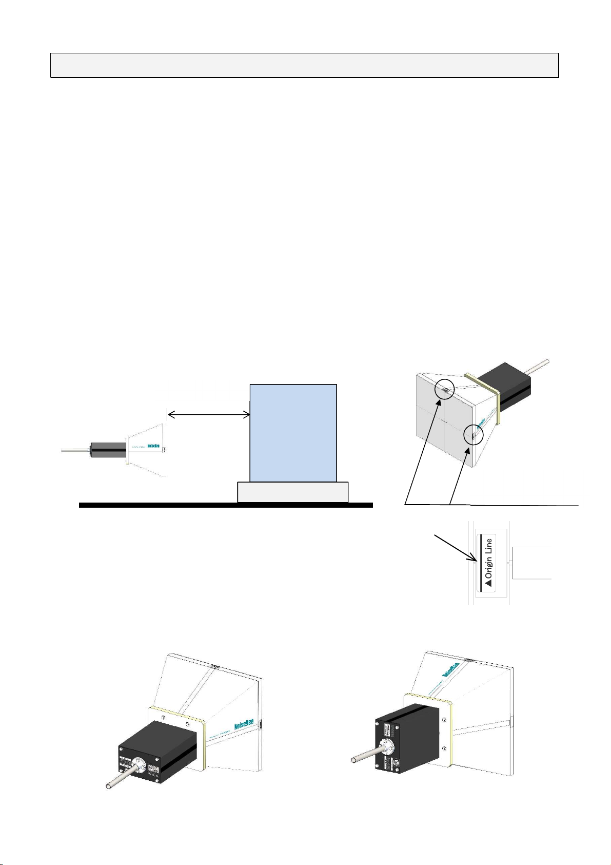
According to the IEC61000-4-39 standard, the TEM horn antenna is tested from the end of the
antenna element to the surface of the EUT at the distance specified by the standard.
The end of the antenna element of this product is located at the black line on the left, right, and top
of the front cover. Use the distance from that line to the EUT surface as specified by the standard.
Also, for vertical polari ation and hori ontal polari ation, rotate the antenna as shown below.
Black line indicating the
position of the antenna
element end
EUT
Distance specified
by the standard.
Black line
Vertical polari ation Hori ontal polari ation

12
9. CHARACTERISTIC DATA
9-1. VSWR (typ.)
9-2. Input Power for 300V/m at 0.1m (typ.)
CHARACTERISTIC DATA
13
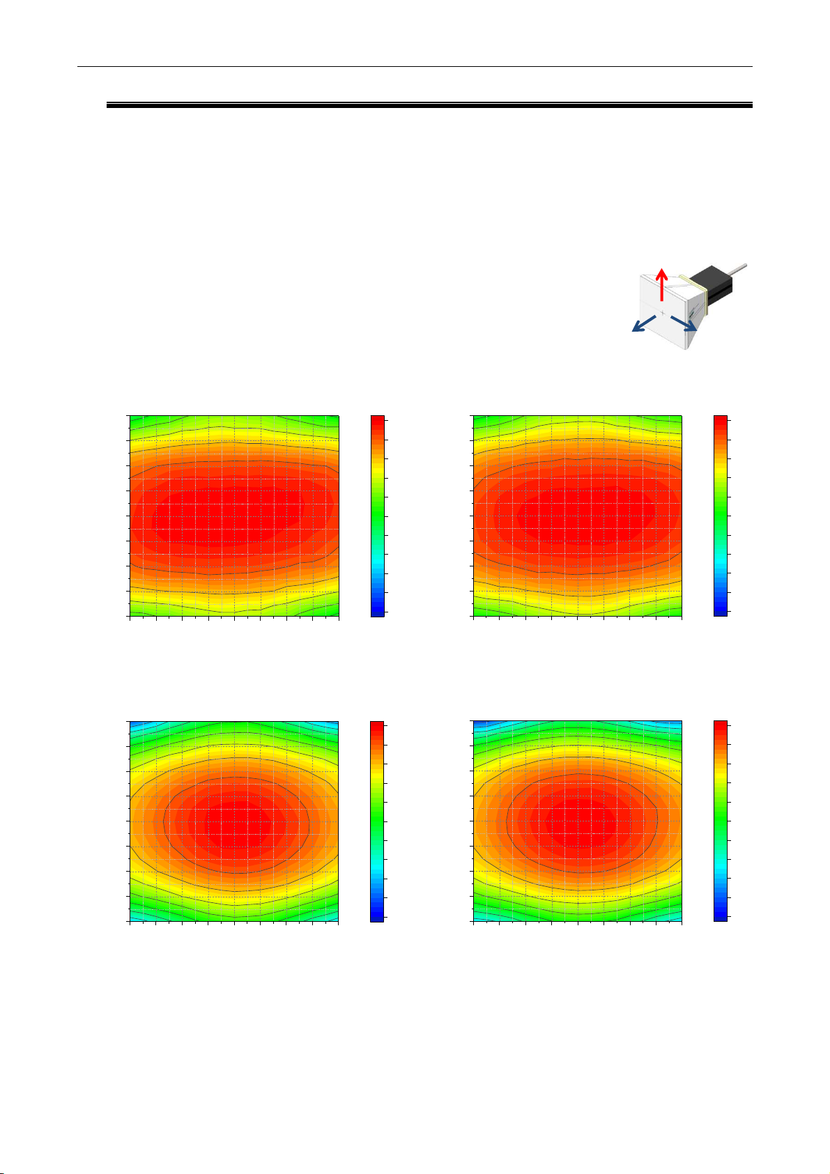
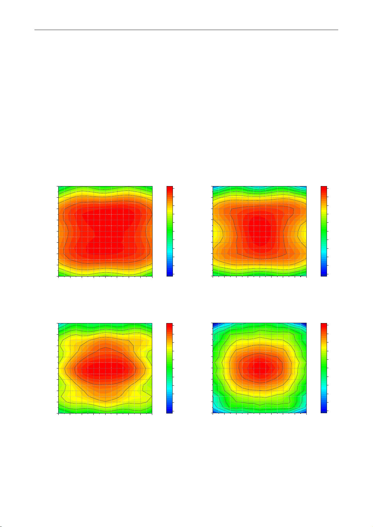
9-3. Electric field distribution characteristics at 0.1m (typical)
It is an electric field distribution map of each frequency at a distance of 0.1 m from the antenna
element.
The electric field distribution map in the figure is for vertically polari ation. The contour lines in the
figure are drawn every -2dB.
385 MHz
745 MHz
450 MHz
870 MHz
-200 -150 -100 -50 0 50 100 150 200
-200
-150
-100
-50
0
50
100
150
200
X [mm]
Y [mm]
-20.00
-18.00
-16.00
-14.00
-12.00
-10.00
-8.000
-6.000
-4.000
-2.000
0.000
dB
-200 -150 -100 -50 0 50 100 150 200
-200
-150
-100
-50
0
50
100
150
200
X [mm]
Y [mm]
-20.00
-18.00
-16.00
-14.00
-12.00
-10.00
-8.000
-6.000
-4.000
-2.000
0.000
dB
-200 -150 -100 -50 0 50 100 150 200
-200
-150
-100
-50
0
50
100
150
200
X [mm]
Y [mm]
-20.00
-18.00
-16.00
-14.00
-12.00
-10.00
-8.000
-6.000
-4.000
-2.000
0.000
dB
-200 -150 -100 -50 0 50 100 150 200
-200
-150
-100
-50
0
50
100
150
200
X [mm]
Y [mm]
-20.00
-18.00
-16.00
-14.00
-12.00
-10.00
-8.000
-6.000
-4.000
-2.000
0.000
dB
Y
X
Z
Electric field direction:
CHARACTERISTIC DATA
14
1455 MHz
2450 MHz
1845 MHz
5500 MHz
-200 -150 -100 -50 0 50 100 150 200
-200
-150
-100
-50
0
50
100
150
200
X [mm]
Y [mm]
-20.00
-18.00
-16.00
-14.00
-12.00
-10.00
-8.000
-6.000
-4.000
-2.000
0.000
dB
-200 -150 -100 -50 0 50 100 150 200
-200
-150
-100
-50
0
50
100
150
200
X [mm]
Y [mm]
-20.00
-18.00
-16.00
-14.00
-12.00
-10.00
-8.000
-6.000
-4.000
-2.000
0.000
dB
-200 -150 -100 -50 0 50 100 150 200
-200
-150
-100
-50
0
50
100
150
200
X [mm]
Y [mm]
-20.00
-18.00
-16.00
-14.00
-12.00
-10.00
-8.000
-6.000
-4.000
-2.000
0.000
dB
-200 -150 -100 -50 0 50 100 150 200
-200
-150
-100
-50
0
50
100
150
200
X [mm]
Y [mm]
-20.00
-18.00
-16.00
-14.00
-12.00
-10.00
-8.000
-6.000
-4.000
-2.000
0.000
dB

CHARACTERISTIC DATA
15
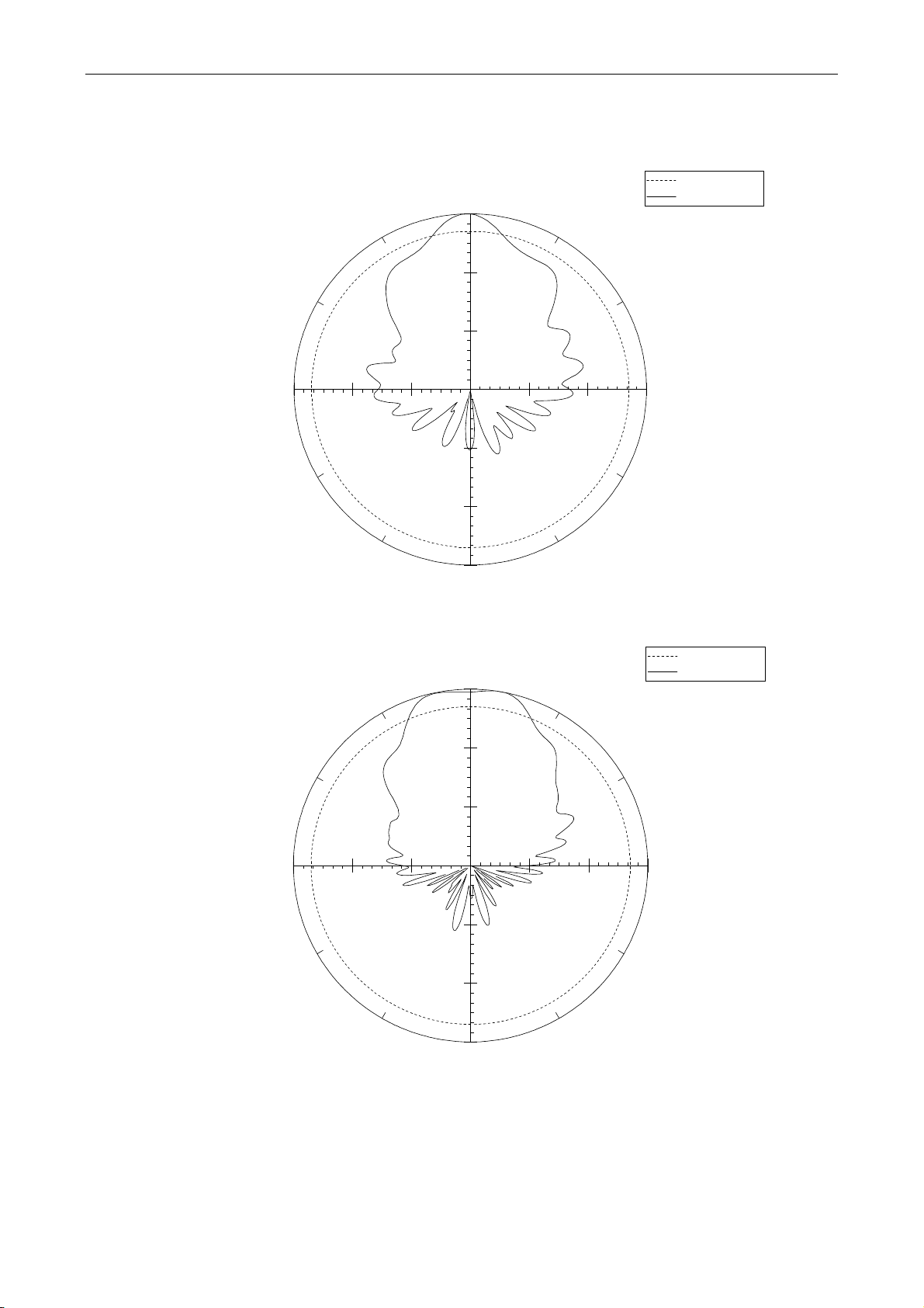
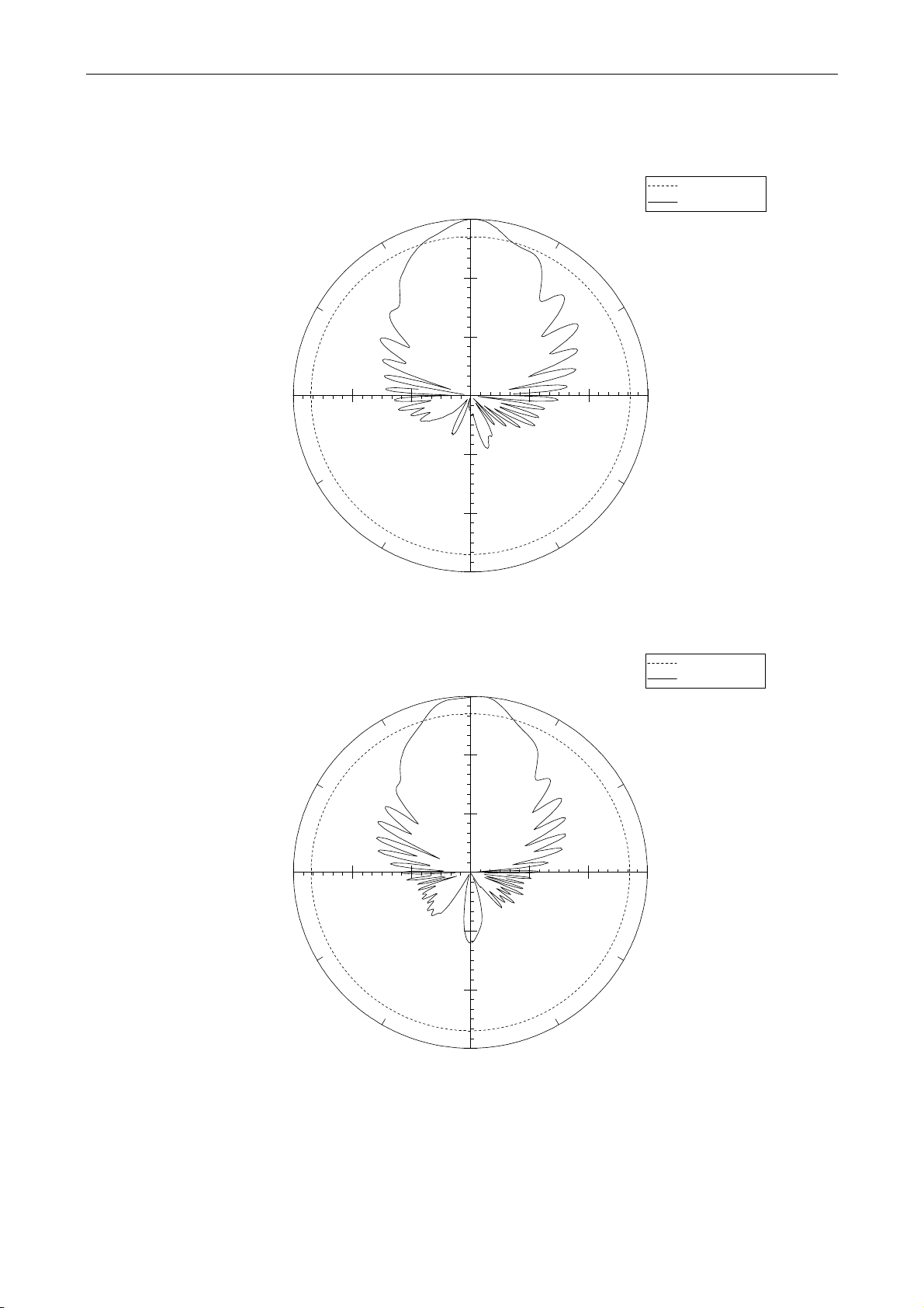
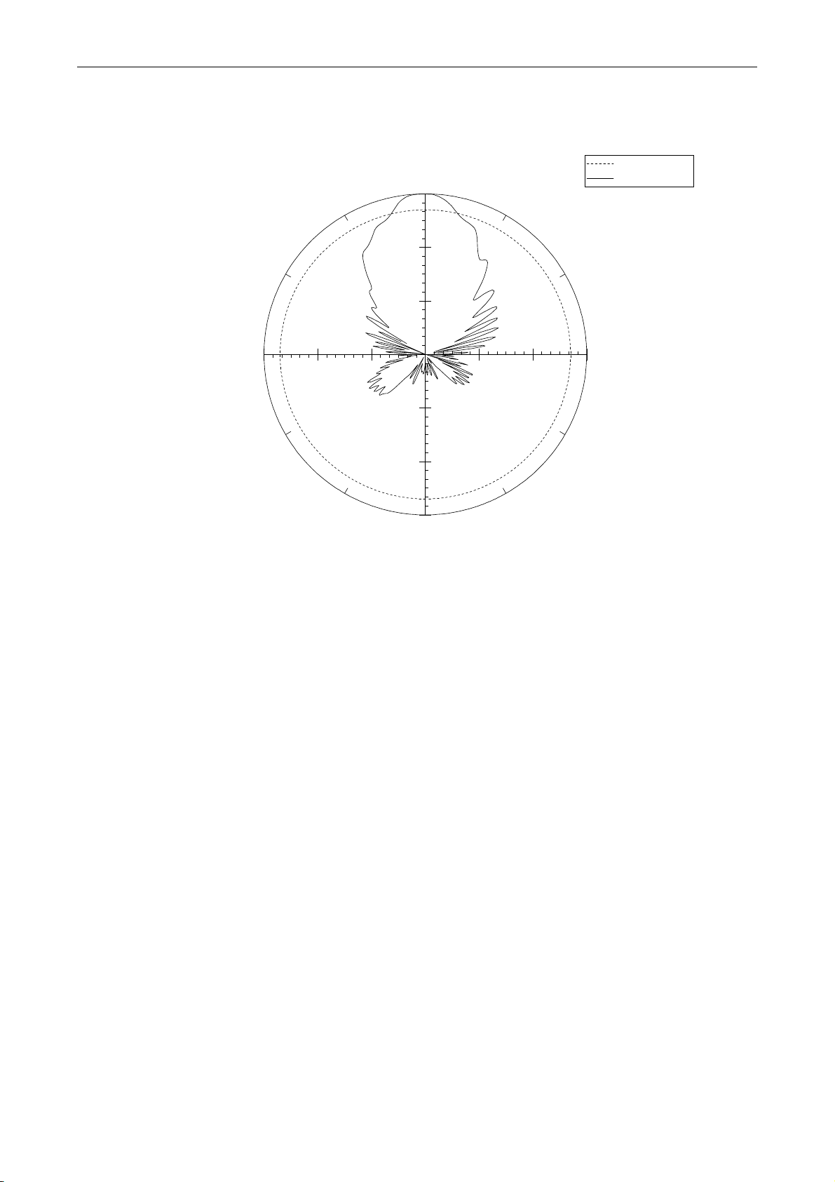
9-4. Antenna Radiation Pattern (typ.)
E-Plane
0
30
60
90
120
150
180
210
240
270
300
330
-30 -20 -10 0
380MHz
-3dB
Measurement
0
30
60
90
120
150
180
210
240
270
300
330
-30 -20 -10 0
1000MHz
-3dB
Measurement
CHARACTERISTIC DATA
16
0
30
60
90
120
150
180
210
240
270
300
330
-30 -20 -10 0
2000MHz
-3dB
Measurement
0
30
60
90
120
150
180
210
240
270
300
330
-30 -20 -10 0
3000MHz
-3dB
Measurement
CHARACTERISTIC DATA
17
0
30
60
90
120
150
180
210
240
270
300
330
-30 -20 -10 0
4000MHz -3dB
Measurement
0
30
60
90
120
150
180
210
240
270
300
330
-30 -20 -10 0
5000MHz
-3dB
Measurement
CHARACTERISTIC DATA
18
0
30
60
90
120
150
180
210
240
270
300
330
-30 -20 -10 0
6000MHz
-3dB
Measurement
Table of contents
Other NoiseKen Antenna manuals


