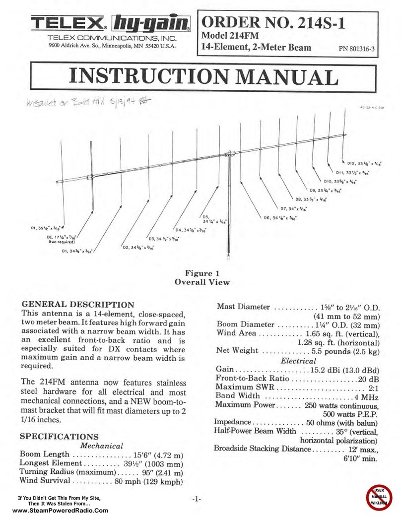
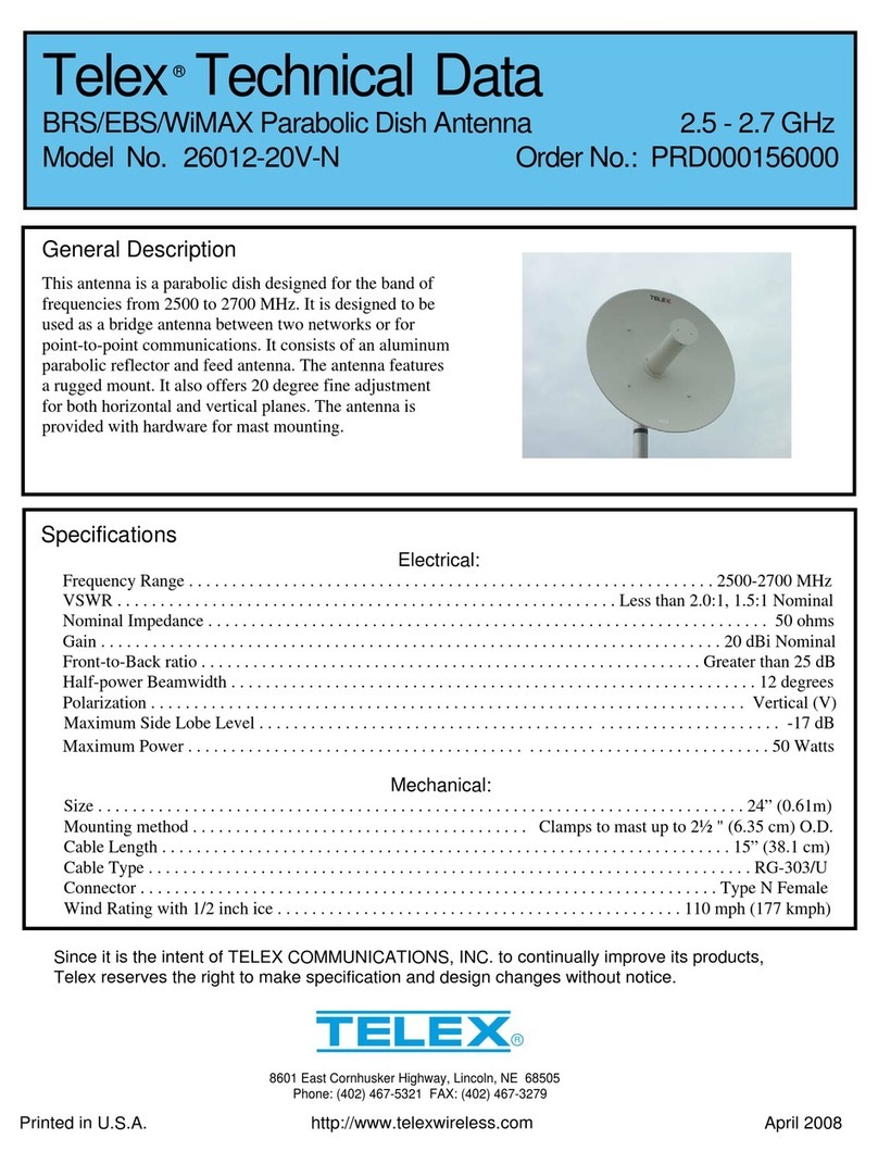
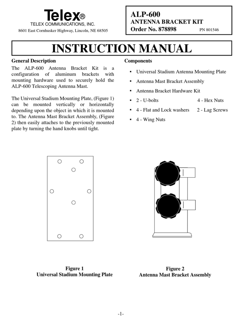
Telex hy-gain 25FM User manual

www.SteamPoweredRadio.Com
TELEX
COMMUNICATIONS
INC.
'9600 Aldridl Ave.
So
.•
Miooeapolis. MN 55420 U.S.
A.
ORDER NO. 205S-1
Model25FM
.5-Element, 2·MeterBeam PN801313-2
INSTRUCTION MANUAL I
General Description
This
antenna
is a 5-element, 2-rneter beam op-
timum
spaced
on
a
7Y
boom.
It
featui,
s
high
forward gain and an excellent front-to-back ratio.
The antenna is end mounted giving it the ad-
vantage
of
no
mast
decoupling
and
a
broad
frequency response. Thi antenna now
u~
tain-
less steel hardware in most locations except for
the U-bolts. Also, this antenna now features a
NEW boom-to-mast bracket that fits up
to
a mast
diameter
of
2 1/16 inches.
SWR
and
Fe
•edline
The 25FM antenna has an input impedance
of
200
ohms.
The supplied balun matches the input
to
50
ohms.
If
you are using transmission line
with a characteristic impedance other than 50
ohms or 200 ohms., a match'ng device must be
made. Refer to any current Amateur Handbook
for
information
on
constructing
a matt:hing
d-vice.
}"f
!iij!l!i!~~l!!liiij!l!l~
SpecificatiQns
..
.
.. ..
.
/J:C<i:>>t\
Mechatdca£.
· -
··
·
•
!~:!::•·.
~
~ll~lJ~
!i
il
l:
~
ii~:
i
::~!~'.=~:
:
::
·:
0::
::~
~::::::
'
::
:
:!::!:::
~
:~:
:::
:
::.::::
::
:.:::
~
::.
~
::
:
::~:
~::
;n1:
ti:~
"
::~
·····

www.SteamPoweredRadio.Com
A0 -
oeo
11
-c-001
2 7 8 9
\ \ \
Item
No. Description
2
Tub
e, Driven Element, aluminum, 7/16"x1
71/
4"
6 Tube,
Rl
, aluminum, 3/16"x
39
5
/8"
7 Tube, D1, aluminum, 3/16"x 36 7/
8"
8
Tube
,D2,aluminum, 3/16"x353/4"
9
Tub
e, D3, aluminum, 3/16"x 35 3/8"
BETA ROD
D3
D2 D1
DE
R I
11
18J 1
~.
_
__
20
14 "
__
___.
...___
__
15
1
12" _ I 91
14" J
3'1.'
'~
_ _
16
318" - -
--"•
l•
,.__
Blt
2" I
(4.
76cm)
(51.43c
m) (39.
37
cm)
-+7
23
.49 c
m)
(8
.
25cm)
(4 1
59
cm)
(21.5
9 c
;;;r\
75
" BO
OM
Figure 1
Overall
View
and Boom Detail
Tuning
NOTE:
The Driven and Parasitic Elements
are
adjusted independently in the following manner:
Parasitic Elements: This antenna
is
pretuned
for maximum gain and best radiation pattern
at
146
MHz
. This setting will give optimum
performance over the entire 144-148
MHz
band.
If
you wish to optimize the antenna for a
frequency higherthan
146
MHz, cut
1/4"
off
of
thetotalelementlengthsfor each MHzhigher
than 146.
-2-
Driven Element: SWR can
be
lowered to less
than 1.2:1
at
a desired frequency
by
carefully
trimming the driven element. Keep The
element symmetrical
by
cutting the same
amount from each side. Typical SWR curves
are shown inFigure 2A, and a cutting chart is
shown in Figure 2B. Each installation is
slightly different, so cutthedriven element for
the lowest SWR at your particular location.
Measure the SWR as close to the antenna as
youcanfor accurate results.

www.SteamPoweredRadio.Com
Z,2
z.o
,..
,..
1.
4
1.2
,.o
m
ITT
~
-
~
-
~ ~
~
00
~
t
◄ 4
IIIIHI
-----
--
fr•---~ M WHt
l
◄
I
MHt
MIWH,1-
•-·-
Figure2A
VSWR forBothVertical
and Horizontal Polarization
Stacking
This antenna can
be
easily stacked for ap-
proximately 3
dB
more
gain each time the
number
of
yagi is doubled.
Refer
to
Figure3 for
stacking
and
phasing harness cutting informa-
tion.
AO·
A-0205
•A-
006
.....
r--
~
17
~
r--
c
.,
E
.,
.;
..... .....
-
.i 161
/z
i,
--
0
.c
O>
~
16
144
145 146
147 148
Frequency in MHz
Figure2B
Driven Element Cutting Chart
The
two phasing lines coming from the two an-
tennas
to
the
'T'
connector can
be
any
odd
multiple
of
1/4 wavelength
in
the
75 ohm trans-
missionline. SeeFigure4.
NOTE:
When
phasing two antennas, the Driven
Element
halves
that
are
connected directly to the
phasing lines should
be
on
the
same side
of
th
e
array.
A0·0205·C
-
002
Figure3
StackingTwo (2) Antennas
-3-

www.SteamPoweredRadio.Com
The
feedline impedance
is
for 50 ohms
(RG-
213/U). For detailed information on stacking
more than two yagis, please consult a current
Amateur Handbook.
~
~
PLUG
END
6
NOTE:
The
boom-to-mast bracket may be
placed between the Driven Element and D1
whenstacking two antennas.
2
A0-0203-A
-
006
ANTENNA
END
-
------
-
67°
--
----
-
-~
RG
-
11
/U
OR
ANY
75-0HM
COAX
5/4
A.
=
67"
3/4
A.
=40"
7
/4,\=93
1
/2
11
%
A.
=120
11
Figure4
Phasing
Line
Cutting
Dimensions
Installation
This antenna fits a
2"
mast. A
2"
O.D. pipe
is
recommendedfor a sturdy mast.
Mountthe antenna inthe clear. Surrounding ob-
jects-particuJarlypower lines and otherobjects
of
considerable mass
or
length-
aredetrimental
to theperformance
of
the antenna.
WARNING
Do
not allow any part
of
the
antenna to
touch power lines. This could cause
severe burns
or
fatal injuries.
When mounting two dissimilar antennas on the
same mast,
be
sure they are separated by
at
least
three feet
(1
m).
-4-
The
antenna can
be
mounted eithervertically or
horizontallyfor
FM
or
SSB/CW
respectively.
Circular polarization can
be
obtained
by
using
two yagis.
For
information aboutwhich polariza-
tion
is
best, consult local Amateurs who use the
frequencies you desire.
Step-by-StepAssembly
Remove the parts from the carton and check
themagainst the parts list and the illustrations.
Select the boom-to-mastbackup plate (ItemNo.
5),
the
boom-to-mast clamp (ItemNo. 4) and the
four (4) 1/4"-20x
3/4"
bolts, lockwashers andnuts
(ItemNos. 16,
26,
and 23).

www.SteamPoweredRadio.Com
23
21
26
24
11/J.
.
-<t-
.
...,.,.
.
..
.
__
~
,,,..
- - ~
'I!'"
·
13-~
--.--
--~
-·--
,
.____
_____
,.
~:-
Item
No.
1
4
5
13
15
5
Description
Tube,
Boom,
aluminum,
11/4"
x 75"
Clamp,
Boom-to-Mast
Backup
Plate,
Boom-to-Mast
Caplug,
11/4"
U-
Bolt,
5/16"-18 x 3
5/8"
'
I
I I
I I
SEE
DETAIL
A
~---
Item
No.
16
21
23
24
26
Description
Bolt,
hex
head,
1/4"-20x
3/4
"
Nut
, hex, 5/16''-18
Nut,
hex, 1/4"-20
Lockwasher,
split,5/16"
Lockwasher,
internal,
1/4
"
Figure5
Boom-to-Mast
Clamp
Assembly
I
I
I I
II
A0
·0
205·A·007
Item
No. Description
A0 ·
0205·
B-009
15
11
3/
11
ELEMENT
U/
16
1
Tube,
Boom,
aluminum,
11/4"
x
75
"
•
//
I I
18
Eyebolt,
5/16",
#10-24
x 11/2"
22
Nut,
hex,
#10-24
25
Lockwasher,
internal,
#10
27
Half
-
Washer,
aluminum
Figure 5 -DetailA
ParasiticElementAttachment
-5-

www.SteamPoweredRadio.Com
Item
No.
3
10
11
12
14
--
TAPE ( 3
PLACES)--_J
Description
BetaRod,3"
Balun Assembly
Insulator (Driven Element-to-Boom)
Beta
Clip
Caplug,
7/16"
A0-0205-8-008
~14
~DRIVEN ELEMENT
3
BRAID
Item
No. Description
17 Bolt, hexhead, #10-24x21/2"
19 Bolt, hexhead, #10-24x11/2"
22
Nut, hex, #10-24
25 Lockwasher, internal,
#10
Figure5-Detail B
Driven Element, Beta Match
and
BalunAssembly
Place the boom-to-mast clamp
on
the boom as
shown
in
Figure 5. Use the l/4"-20x 3/4" bolts in
the outside holes. Leave the inside holes for the
two U-bolts, which will
be
used laterfor mount-
ing the mast. Select either the vertical
or
horizontal mounting position. Adjust the
boom
accordingly before tightening
the
bolts securely.
Select the 3/16" x 39 5/8"
Rl
tube (Item No. 6),
use
penciltoplacea mark
at
thecenter
of
therod
(19 13/16" from either end) and place two more
marks 5/
8"
from eachside
of
the
ce
nte
r mark.
-6-
Placea #10-24x 11/2"eyebolt (ItemNo. 18) into
the
Rl
slot as shown
in
Figure 5, Detail A Slide
the
Rl
through the holes and the eyebolt until
theoutertwomarks
on
the
Rl
arevisible
on
each
side
of
the boom. Slip
on
an
aluminum half
washer, a lockwasher and a
#10
nut
(ItemNos.
27,25, and22).Tighten
it
justenough to holdthe
rodsecurely.
DO
NOT
OVER
TIGHTEN.

www.SteamPoweredRadio.Com
Select
the
element-to-boom insulator (Item No.
11), two sections
of
the
Driven
Element
(7/16" x
17 1/4") tubing
(Item
No. 2) and
beta
rod
(Item
No. 3).
NOTE:
If
50
ohm
coaxialcableisusedtofeed
the
antenna,
se
lect
the
supplied
balun
at
this time.
Use
the
#10-24x 21/2"bolt (ItemNo. 17)
to
fas-
ten the
element-to-boominsulator
to
the
boom.
Refer to Figure5, DetailB.
Use
the two (2) #10-24x 11/4"bolts (Item No.
19) to assemble
the
DrivenElementas shown
in
Figure
5,
Detail
B.
Payparticularattention
to
the
connections
of
the
beta
rod, balunand feedline.
Waterproof
the
connection with neoprene,
Krylon®,
or
somesimilarsubstance.
Install caplugs
on
the
ends
of
the
boom
and the
DrivenElement.
Kiylon®
isa
registered
trademarlt
of
Borden
Chemical
Co.
-7-
Use
the
# 10x 3/8" screw (Item No. 20) to fasten
the
beta
rod
shorting clip over
the
beta
rod,
as
shown
in
Figure
5,
DetailB.
Select
the
following rods:
Dl
(367/8" long) (Item
No. 7),
D2
(353/4
11
long) (ItemNo. 8) andD3 (35
3/8" long)
(Item
No.9). Mark
the
centerpoint
on
each rod,
then
make two
more
marks
5/8"
on
either side
of
the
center mark. Secure the ele-
ments to
the
boom
as shown
in
Figure l and
Figure
5,
Detail A. Be sure they
are
oriented as
shown.
Slip
the
two (2) U-bolts into
the
boom-to-mast
bracket and fasten
it
to
the
mast securely. Tape
the
coaxfeedline to the
boom
andto
the
mast.
Be
sure to insulate any connections from
the
boom
or
the
mast.This completesyour installation.

www.SteamPoweredRadio.Com
PARTS LIST
Item
No.
Part No. Description Qty
1 170386
Tube,
Boom,
aluminum, 1 1/4" x 75".................................................1
2 175157
Tube,
Driven
Element,
aluminum, 7/16" x
171/4"
..........................2
. 3 160040
Beta
Rod,
3" .......................
..
................................................................1
J 4 385142-1
Clamp,
Boom-to-Mast
............................................
..
..........................l
~ 5 385144-1
Backup
Plate,Boom-to-Mast............................................................1
: 6 160036
Tube,
Rl
, aluminum, 3/16"x
39
5/8"......................................
..
.........1
,.
7 160016
Tube,
Dl,
aluminum, 3/16"x
36
7/8".................................................1
't
8 160019
Tube,
D2,
aluminum, 3/16"x
35
3/4".................................................1
• 9 160021
)o
871704 .
;11 465420
Tube,
D3,
aluminum, 3/16"x
35
3/8".................................................1
Balun
Assembly.............
..
....................................................................1
Insulator
(Driven
Element-to-Boom)
..............................................1
;-
872073-1
Parts
Pack
205S-1, Stainless
Steel
.....................................................1
l2
163266
Beta
Clip................................................................
..
...........
..
.............1
.,13
455630 Caplug,
11/4"
........................
..
..........................................................2
14 475639 Caplug, 7/16" ...................................................................
..
................2
15 540067 U-Bolt, 5/16"-18x 35/8"..................................................................2
16 505266 Bolt,
hex
head,
1/4"-20x 3/4
11
..
.
....
...............................
...........
.........
4
17
500164
.
is 540065
i9
500159
Bolt
,
hex
head, # 10-24x 2 1/2"..................................................
....
.1
Eyebolt,5/16",
#10-24
x
11/2"
........................................................4
Bolt,
hex
head, # 10-24x
11/2"
.......................................................2
zo
510670 Screw,
pan
head,
Type
A,
# 10x
3/8"
...
....
......................................1
21 555747
Nut,
hex, 5/16"-18 .............................................................................4
22 554071
Nut,
hex,
#10-24
.............................................................................11
23
554099
Nut,
hex, 1/4"-20...............................................................................4
24 564792 I..ockwasher, split, 5/16"...................................................................4
25 565697 I..ockwasher, internal,
#10
............................................................
12
26 562961 I..ockwasher, internal, 1/4"...............................................................5
27 170376
Half
Washer,
aluminum
..................................................................4
CoµvertingAmerican Measurements
to Metric 1 inch (l") = 2.54
cm
1
foot
(1') =
30
.48
cm
Use
this scale
to
identify lengths
of
bolts,
diameters
of
tubes,
etc
..
The
American
inch
(1")
andJoot
(1')
can
be
converted
to
centimeters
in
tliliway.
U.S.A.
Example:
42" x 2.54 = 106.7
cm
0 1 2 3 4 5 6
111,1
l
~,J,~11
~1!1
~hi
111
,,,
1,,,1~
!I
,1t1~1l
'11
ii,,
1,+11I
1j,1l,1l,1!111,,1111
l,1
,,,l,,,
,,,,\
I\
l,1~1,I
~l!~I
IAf
,11!
11
,I
0 1 2 3 4 5 6 7 8 9
10
11
12
13
14
15
METRIC
PRINTED
IN
U.S.A.
Cop
yrightC 1993
by
Telex
TELEX
COMMUN
ICATIONS,
INC
.
All
rights
reserved.
I Sept
199
3 -8-
This manual suits for next models
1
Table of contents
Other Telex Antenna manuals

Telex
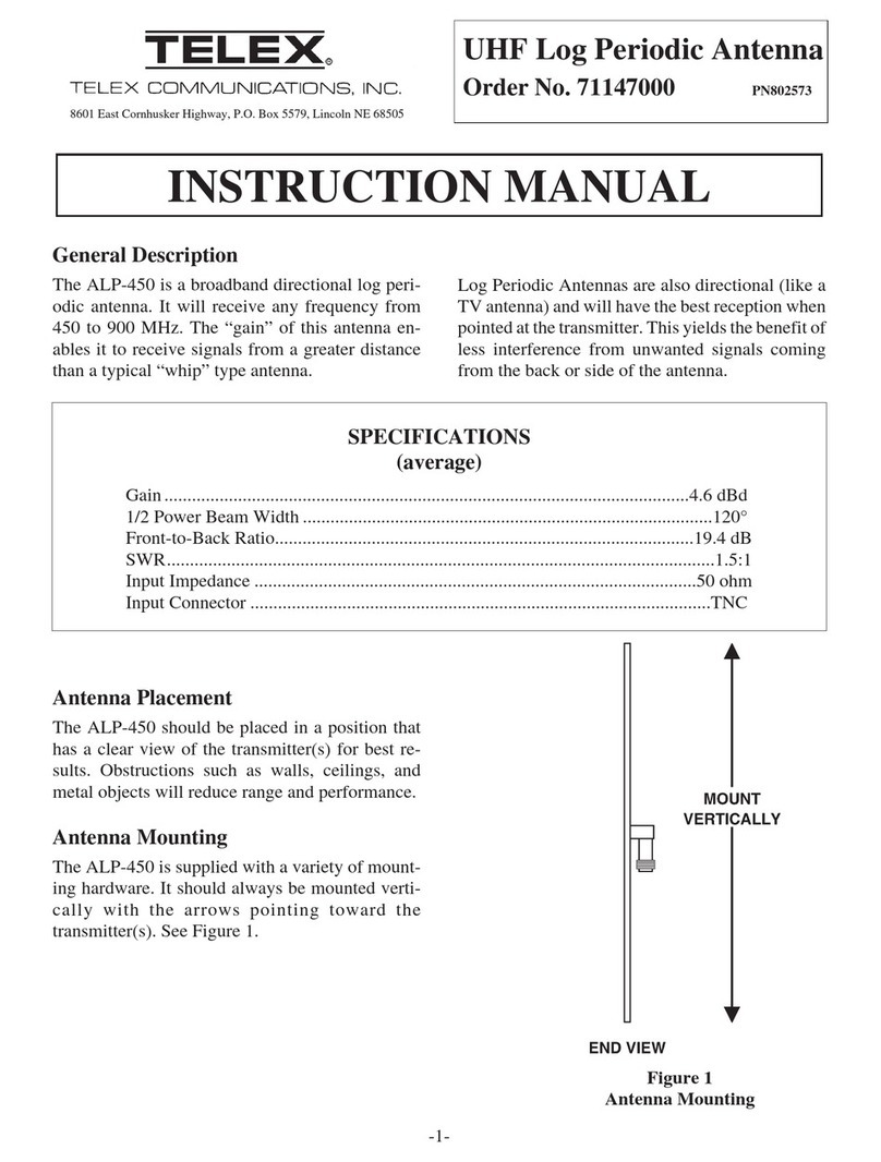
Telex ALP-450 User manual

Telex
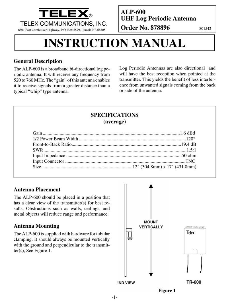
Telex ALP-600 User manual

Telex
Telex ALP-600 User manual

Telex
Telex ALP-600 User manual

Telex
Telex 26012-20V-N Instruction manual

Telex
Telex ALP-600 User manual

Telex
Telex ALP-600 User manual

Telex
Telex hy-gain 214FM User manual

Telex
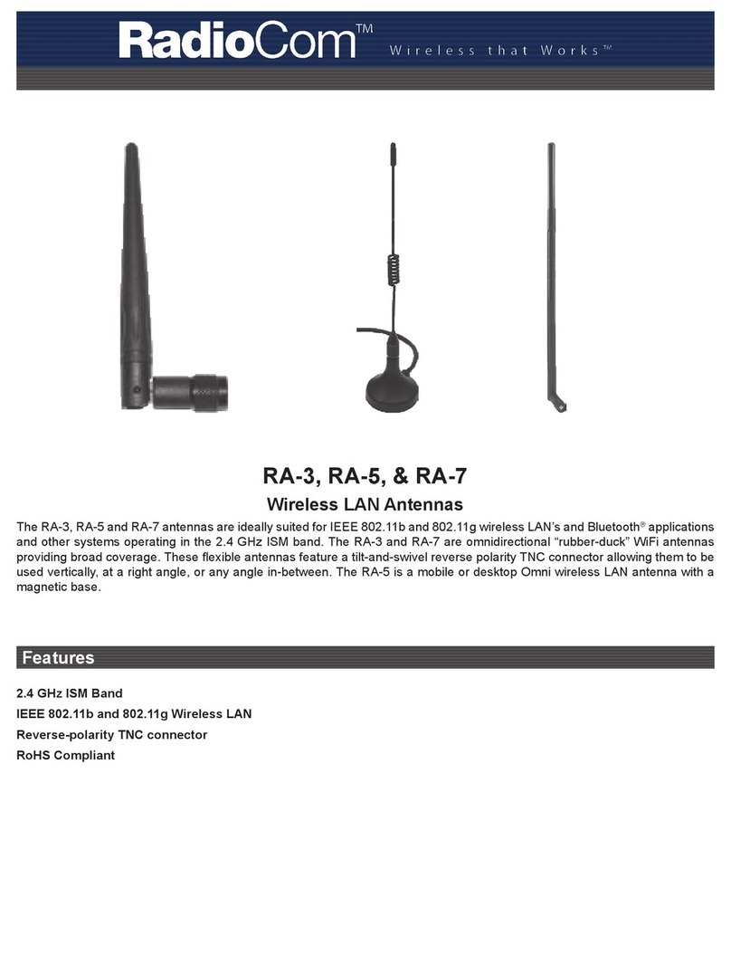
Telex RadioCom RA-3 User manual

Telex
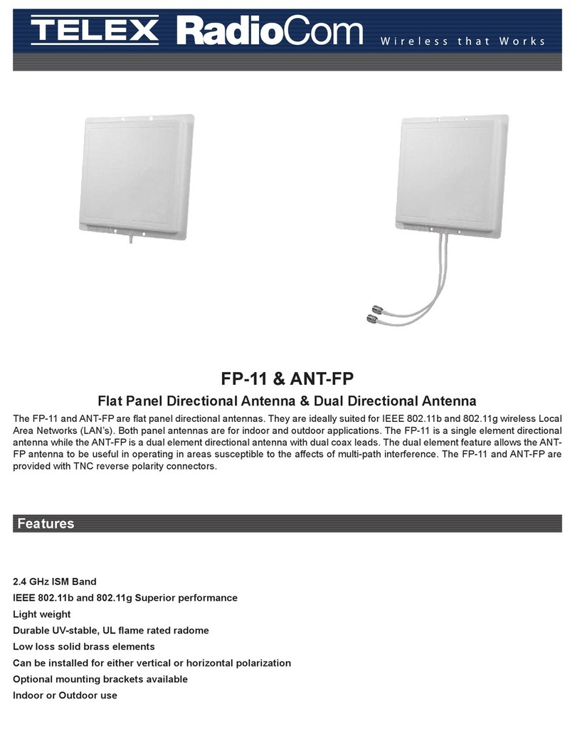
Telex RadioCom ANT-FP User manual