FIGURE 10C
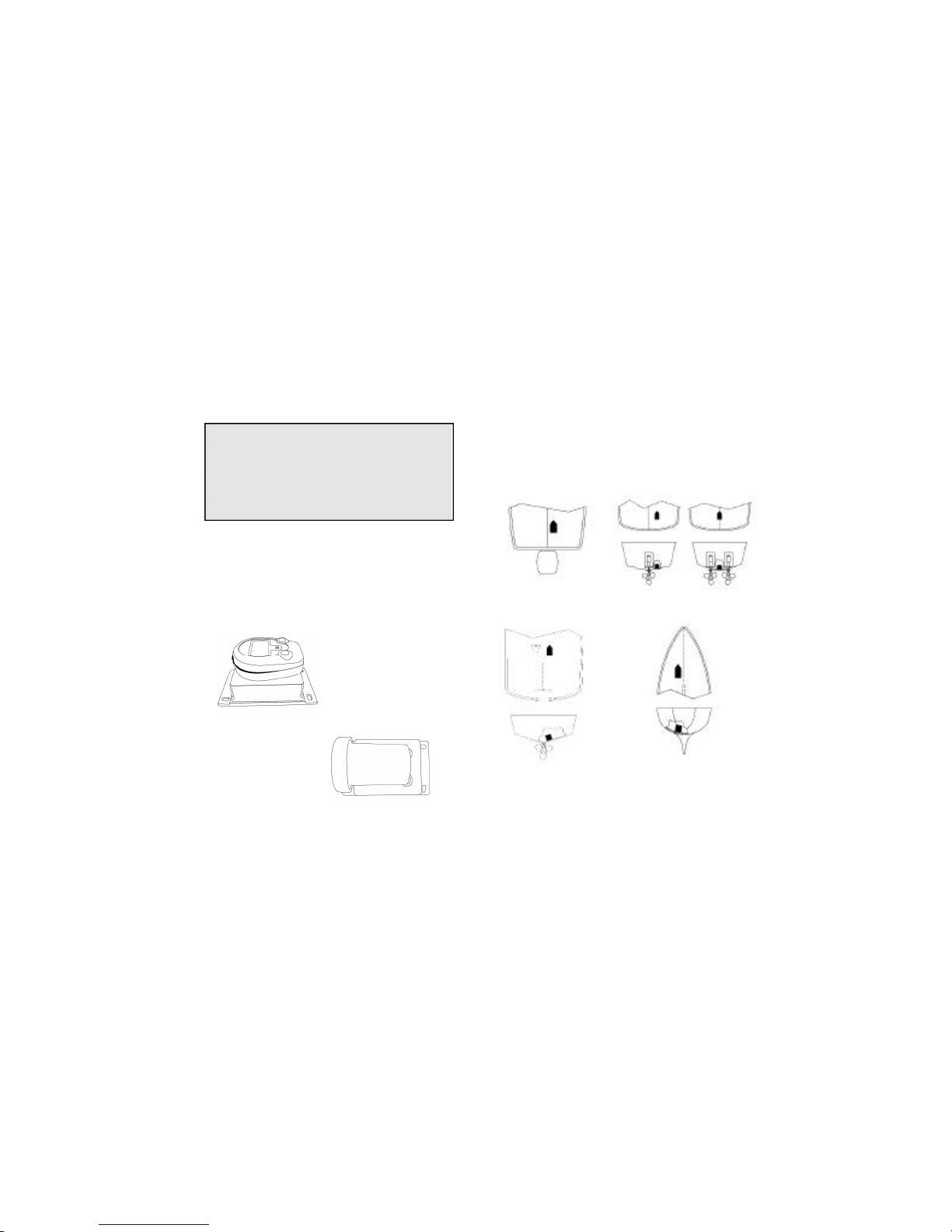
If the hull surface is not smooth, grind it with a disc
sander. Partially fill a thin plastic bag with water, place the
transducer inside and close it tightly with a tie wrap. Wet
the surface of the hull and press the transducer face
against it through the bag (Figure 20 C).
Selecting the Adhesive
Hard adhesives, transmit sound best, but winter tempera-
ture extremes and flexing on trailer rollers can cause it to
delaminate. However, soft adhesives absorb sound. To
compromise, use a viscous slow-cure epoxy or a fairly
rigid, one part adhesive sealant. In cold climates, a one-
part polyurethane adhesive, such as Boat-Life’s Life Seal‚
may be best. Do not use “5 minute” epoxies because they
are generally brittle. RTV (silicone) adhesives are not rec-
ommended because most of the sound energy is lost.
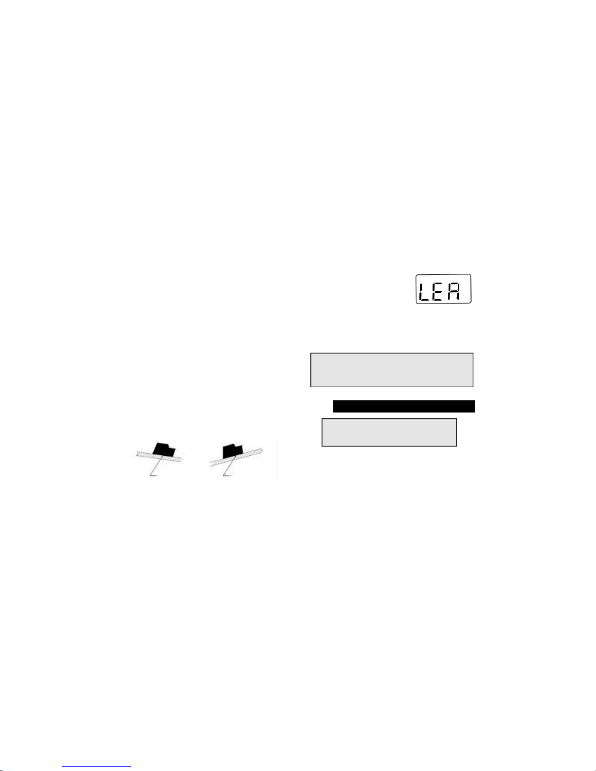
Installation
1. All surfaces to be bonded must be smooth, clean
and dry. If the surface is rough, use a disk sander to
smooth an area a little larger in diameter than the
length of the transducer.
CAUTION!!!!
Always wear safety goggles and a dust
mask when sanding.
35
TABLE OFCONTENTS
Transducer Selection . . . . . . . . . . . . . . . . . . . . . . . . . .
Transducer Installation . . . . . . . . . . . . . . . . . . . . . . . .
Setting up the Transmitter and Receiver . . . . . . . . . . .
Transmitter Installation (ML100T) . . . . . . . . . . . . . . . .
Installing the In-Dash Wireless Display (ML100DR) . . .
Installing the Portable Wireless Display (ML100R) . . .
Operating the Transmitter (ML100T) . . . . . . . . . . . . . .
Operating the Wireless Displays (ML100R, ML100DR)
Warranty Information . . . . . . . . . . . . . . . . . . . . . . . . . .
Specifications . . . . . . . . . . . . . . . . . . . . . . . . . . . . . . .
Accessories . . . . . . . . . . . . . . . . . . . . . . . . . . . . . . . . .
Troubleshooting . . . . . . . . . . . . . . . . . . . . . . . . . . . . . .
In-Hull Transducer Installation (Appendix A) . . . . . . . .
4
5
5
7
10
13
14
15
20
22
23
24
28
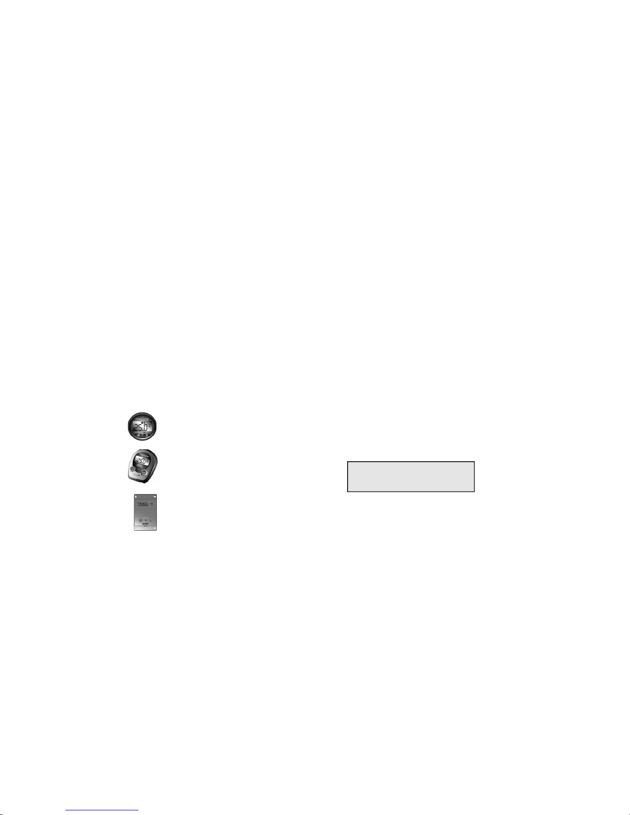
ML100DR In-Dash Wireless Display
**Included within the ML100TDR System.
Additional displays can be added at any time
by following the setup instructions on page 5.
ML100R Portable Wireless Display
**Included within the ML100TR System.
Additional Display can be added at any time
by following the setup instructions on page 5.
ML100T Wireless Depth Sounder Transmitter
**Included within the ML100TR and ML100DTR
Systems. Both the ML100R and ML100DR wireless
displays require the transmitter to function as a
depth sounder display.
Model Identification
2