Nortek Global Reznor LCSA-3 User manual

1/25
1511LCSA-3--EN
Gas-Fired, Balanced-Flue or
Power-Vented Unit Heater
LCSA-3
Installation, commissioning, servicing & user instructions
These appliances meet the following EC Directives
DIR 2009/142/EC: GAD
DIR 2004/108/EC: EMC
DIR 2006/95/EC: LVD
DIR 2006/42/EC MD
Applies to
Austria, Belarus, Bulgaria, China, Czech Republic, Croatia, Cyprus, Denmark, England, Estonia, Finland,
Germany, Greece, Hungary, Iceland, Latvia, Lithuania, Montenegro, New Zealand, Norway, Poland, Romania,
Russian Federation, Serbia, Slovakia, Slovenia, South Africa, Spain, Sweden, Turkey, Ukraine
WARNING
Improper installation, adjustment, alteration, service or maintenance can cause property
damage, injury, or death. All work must be carried out by appropriately qualified persons.
The manufacturer does not take any responsibility in the event of non-observance of the
regulations concerning the connection of the apparatus causing a dangerous operation of the
apparatus, possibly resulting in damage to the apparatus and/or environment in which the unit
is installed.
Please read this document carefully before commencing installation commissioning
and/or servicing.
Leave it with the user or attached to the appliance or gas service meter after installation.
Subject to modifications

2/25
TABLE OF CONTENTS
1.0 INTRODUCTION
1.1 Basic Information
1.2 Warranty
2.0 TECHNICAL DATA
2.1 Specifications
2.2 Dimensions
3.0 GENERAL REQUIREMENTS
3.1 Related Documents
3.2 Heater Location
3.3 Combustion Air Inlet Pipe and Flue Pipe
3.4 Air Supply
3.5 Air Distribution System
3.6 Electrical Supply
3.7 Gas Supply
4.0 INSTALLATION
4.1 Uncrating and Preparation
4.2 Suspending the Heater
4.3 Fitting the Combustion Air Inlet/Flue Pipe System
4.3.1 Fitting the Flue Pipe
4.3.2 Fitting the Combustion Air Socket Guard - Type B Installation
4.3.3 Fitting the Combustion Air Pipe - Type C Installation
4.4 Gas Connection
4.5 Electrical Connections
4.6 Room Thermostat Siting
5.0 AIR DISTRIBUTION
6.0 COMMISSIONING AND TESTING
6.1 Electrical Check
6.2 Gas Connection
6.3 Suspension and Support
6.4 Lighting the Heater
6.4.1 To Turn the Heater ON
6.4.2 To Turn the Heater OFF for Short Periods
6.4.3 To Turn the Heater OFF for Long Periods
6.5 Heater pipe work
6.6 Adjustments
6.7 Air Distribution System
6.8 Heater Controls
6.9 Handing Over
7.0 SERVICING INSTRUCTIONS
8.0 REMOVAL AND REPLACEMENT OF PARTS
8.1 Main Burner Removal
8.2 Main Burner Injectors
8.3 Ignition System
8.4 Operating Gas Valve
8.5 Limit Controls
8.6 Combustion Air Pressure Switch
8.7 Combustion Air Fan
9.0 FAULT FINDING
10.0 PARTS LIST
11.0 GAS CONVERSION
12.0 USERS INSTRUCTIONS
13.0 HEALTH & SAFETY STATEMENT
3/25
HAZARD INTENSITY LEVELS
DANGER Failure to comply will result in
severe personal injury or
death and/or property
damage.
WARNING Failure to comply could result
in severe personal injury or
death and/or property
damage
CAUTION Failure to comply could result
in minor personal injury
and/or property damage.
WARNING: The electrical isolator should
only be used in an emergency and should
not be used for closing down the main
burner, as it switches off the fan
prematurely and may damage the heat
exchanger, invalidating the warranty.
Attention :
This appliance is not intended for use by
persons (including children) with reduced
sensory or mental capacities, or lack of
experience and knowledge, unless they have
been given supervision or instruction
concerning use of the appliance by a person
responsible for their safety.
Children should be supervised to ensure that
they do not play with the appliance.
INTRODUCTION
1.1 Basic Information
The instructions in this manual apply to Model LCSA-
3 gas-fired/fan-assisted warm air heaters. These
models have an axial fan for air delivery. These
heaters are designed for overhead suspension and
are suitable for indoor installation only installed at an
operation ambient temperature between -15°C and
45°C. When installed as a type C12/C32 and where
the height above floor level is greater than 1.8
meters measured to the underside of the appliance
they may be used as a garage air heater. This
appliance must be installed in accordance with the
rules in force. Before installation, check that the
local distribution conditions, nature of gas and
pressure and adjustment of the appliance are
compatible.
A permanent electricity supply of 230 volts, 50 Hz,
single phase is required.
Heaters are approved for:
Type C12 - horizontal vent for balanced-flue heaters;
Type C32 - vertical vent for balanced-flue heaters;
Type B 22 - vertical vent;
When the external control calls for heat, an
electronic control begins the ignition sequence to
provide for a safe start. About 30 seconds after the
call for heat, the fan will begin circulating warm air.
The electronic control will supervise the flame during
the entire heating cycle to ensure safe operation.
When the required room temperature is reached, the
main burner will shut down leaving the fan running to
cool down the heat exchanger. After approximately
45 seconds, the fan delay relay will turn off the fan.
1.2 Warranty : Warranty is void if:
dan
g
er
a) LCSA-3 heaters are installed in atmospheres containing flammable vapors or atmospheres
containing chlorinated or halogenated hydrocarbons or atmospheres containing any silicone,
aluminum oxide, etc., that adheres to spark ignition flame sensing probes.
b) The installation is not in accordance with these instructions.
c) Axial fan-type unit heater is connected to a duct system or fitted with a non-authorized air
distribution device.
1

4/25
LCSA 12-3 20-3 30-3 35-3 45-3 50-3 60-3 75-3 100-3 120-3 145-3
Gas category
Comb. Air & Flue, type B
(1)
Comb. Air & Flue, type C
(1)
Connection collars mm 80 100 100 130 130 130 130 130 130 130 130
Heat input Hs kW 13,33 26,42 31,63 43,95 54,38 61,08 73,25 87,85 114,87 144,81 165,47
Heat input Hi kW 12,00 23,80 28,50 39,60 49,00 55,00 66,00 79,15 103,50 130,40 149,00
Heat output kW 11,14 21,82 25,99 36,23 44,64 50,77 60,92 73,13 94,50 119,32 137,39
Thermal Efficiency % 92,80 91,70 91,20 91,50 91,10 92,30 92,30 92,39 91,30 91,50 92,20
m³/h 1,27 2,52 3,02 4,19 5,19 5,82 6,98 8,38 10,95 13,80 15,77
kg/h NA 1,86 2,22 3,09 3,82 4,29 5,15 6,17 8,24 10,17 11,62
Gas consumption Lw (20mbar) (*) m³/h NA 3,07 3,68 5,11 6,32 7,10 NA 10,22 NA NA NA
m³/h NA 3,50 4,19 5,82 7,20 8,08 NA 11,63 NA NA NA
Gas pipe connection
(2)
Real temperature rise
(3)
K3031333331303429343235
Air flow measured
(3)
m³/h 1100 2045 2326 3170 4270 5012 5214 7282 8024 10764 11400
Nominal motor speed RPM 1381 1256 1333 1300 1310 928 1346 1344 935 872 875
Recommended mounting height
(4)
m2,53444455566
Horizontal throw
(5)
m9,513 17 24 25 27 30 32 31 38 39
Sound Pressure
(6)
dB(A) 36 42 47 48 48 45 54 55 53 54 55
Sound Pressure
(7)
dB(A) 43 49 54 55 55 52 61 62 60 61 62
Electrical service (protection IP20)
Total electrical rating W 533 363 533 723 723 543 1233 1233 993 723 723
Weight kg 59 59 64 94 99 114 114 126 184 242 279
see table 1B
B22P
C12, C32, C42, C62
Gas consumption G31
Gas consumption G20
230/240V 1N ~ 50Hz
1/2"
Gas consumption Ls (13mbar) (*) 3/4"
(*) : only for Poland
(3) Figure for isothermal conditions.
building,mounting height of the unit, ambient temperature & adjustment of the louvres.
(6) Sound pressure level in dB(A) in free field conditions,measured at 5 metres from the unit
(7) Sound pressure level in dB(A),measured at 5 metres from the unit with A=160m² and Q=2
(5) Isothermal conditions at 20°C ambient air temperature, discharge louvre zero deflection,v = 0,5 m/s.The air throwwill be influenced bythe height of the
(4) Height from floor to bottom surface of heater. These are recommandations only.Positioning of unit heaters for proper performance is application dependent.
Care should be taken to avoid mounting the heaters above these recommendations,unless downturn nozzle options are used,as significant stratificationmay
occur resulting in poor floor coverage and higher energylosses through the roof structure.
line to minimize the pressure drop through the gas pipes - if necessary,reduce the diameter of the supply line at the inlet of the unit.
(1) Gas Appliance Classifications for Aprroved Venting M ethods based on CEN-report CR1749:2001
(2) There is a difference between the gas connection diameter and the diameter of the supplyline.Always use the most adequate diameter of the supply
TECHNICAL DATA
2.1 Specifications
Table 1a
Table 1b : Gas categories
Country Gas category Country Gas category
Austria II2H3P Montenegro II2H3+
Belarus II2H3+ New Zealand II2H3+
Bulgaria I2H or I3P Norway II2H3 B/P
China II2H3+ Poland II2E3P
Czech republic II2H3+ Portugal II2H3+
Croatia II2H3P Romania II2H3 B/P
Cyprus II2H3+ Russian Federation I2H or I3P
Denmark II2H3 B/P Serbia II2H3+
England II2H3+ Slovakia II2H3+
Estonia II2H3+ Slovenia II2H3+
Finland II2H3 B/P South Africa II2H3+
Germany I2ELL Spain II2H3+
Greece II2H3+ Sweden II2H3 B/P
Hungary II2HS3P Turkey II2H3+
Iceland II2H3+ Ukraine I2H or I3P
Latvia II2H3+
Lithuania II2H3+
2

5/25
Table 2 :Injector size and burner pressures
Model1220303545506075100120
Injector quantity 5 5 6 8 10 8 8 10 12 10
mm 1,50 2,10 2,10 2,20 2,20 2,40 2,70 2,70 2,90 3,40
marking 150 210 210 220 220 240 270 270 290 340
Burner pressure (1) mbar 8,10 8,00 7,25 7,10 6,90 9,20 8,50 8,30 7,50 9,20
Inlet pressure mbar
Injector quantity - 5 6 8 10 8 8 10 12 10
mm - 1,15 1,15 1,15 1,15 1,40 1,45 1,45 1,50 1,95
marking - 115 115 115 115 140 145 145 150 195
Burner pressure (1) mbar - 35,80 35,80 36,20 35,90 30,10 35,60 35,40 34,40 30,70
Inlet pressure mbar
Model1220303545506075100120
Injector quantity - 5 6 8 10 8 - 10 - -
mm - 2,40 2,40 2,40 2,40 2,60 - 3,00 - -
marking - 240 240 240 240 260 - 300 - -
Burner pressure (1) mbar - 8,30 8,20 8,35 8,25 11,40 - 9,25 - -
Inlet pressure mbar
Injector quantity - 5 6 8 10 8 - 10 - -
mm- 2,602,602,50
2,60 3,40
-
3,90
--
marking - 260 260 250
260 340
-
390
--
Burner pressure (1) mbar - 8,25 8,45 9,55
8,40 6,00
-
5,25
--
Inlet pressure mbar
Model1220303545506075100120
Injector quantity 5** 5 6 8 10 8 8 10 12 10
mm 1,50 2,10 2,10 2,20 2,20 2,40 2,70 2,70 2,90 3,40
marking 150 210 210 220 220 240 270 270 290 340
Burner pressure (1) mbar 8,10 8,00 7,25 7,10 6,90 9,20 8,50 8,30 7,50 9,20
Inlet pressure mbar
Injector quantity - 5 6 8 10 8 8 10 12 10
mm - 1,15 1,15 1,15 1,15 1,40 1,45 1,45 1,50 1,95
marking - 115 115 115 115 140 145 145 150 195
Burner pressure (1) mbar - 35,80 35,80 36,20 35,90 30,10 35,60 35,40 34,40 30,70
Inlet pressure mbar
(* ): Inlet pressure for Hungary = 25mbar
(**): no nat gas for Germany
Model1220303545506075100120
Injector quantity 5 5 6 8 10 8 8 10 12 10
mm 1,50 2,10 2,10 2,20 2,20 2,40 2,70 2,70 2,90 3,40
marking 150 210 210 220 220 240 270 270 290 340
Burner pressure (1) mbar 8,10 8,00 7,25 7,10 6,90 9,20 8,50 8,30 7,50 9,20
Inlet pressure mbar
Injector quantity - 5 6 8 10 8 8 10 12 10
mm - 1,15 1,15 1,15 1,15 1,40 1,45 1,45 1,50 1,95
marking - 115 115 115 115 140 145 145 150 195
Burner pressure (1) mbar - 28,06 28,06 28,37 28,14 23,59 27,90 27,75 26,96 24,10
Inlet pressure mbar
Model1220303545506075100120
Injector quantity 5 5 6 8 10 8 8 10 12 10
mm 1,50 2,10 2,10 2,20 2,20 2,40 2,70 2,70 2,90 3,40
marking 150 210 210 220 220 240 270 270 290 340
Burner pressure (1) mbar 8,10 8,00 7,25 7,10 6,90 9,20 8,50 8,30 7,50 9,20
Inlet pressure mbar
Injector quantity - 5 6 8 10 8 8 10 12 10
mm - 1,20 1,20 1,20 1,20 1,45 1,50 1,50 1,60 1,95
marking - 120 120 120 120 145 150 150 160 195
Burner pressure (1) mbar - 28,60 28,80 29,20 28,80 28,10 28,50 28,40 27,70 26,40
Inlet pressure mbar
(1) : with open service door
LCSA-3
LCSA-3
Bulgaria, Denmark, Finland, Norway, Sweden
Austria, Germany, Hungary, Russian Federation, Ukraine
Nat. Gas
G20
Injector size
20(*)
Prop. Gas
G31
Injector size
50
Nat. Gas
G20
Injector size
20
Prop. Gas
G31
Injector size
30
G2,350
Injector size
13
Belarus, China, Croatia, Czech Republic, Cyprus, England, Estonia, Greece, Iceland, Latvia, Lithuania, Montenegro, New Zealand, Portugal, Serbia, Sl
o
Slovakia, South Africa, Spain , Turkey, Poland
Nat. Gas
G20
Injector size
20
Prop. Gas
G31
Injector size
37
LCSA-3
LCSA-3
Special poland
G27
Injector size
20
Prop. Gas
G31
Injector size
30
Romania
LCSA-3
Nat. Gas
G20
Injector size
20
6/25
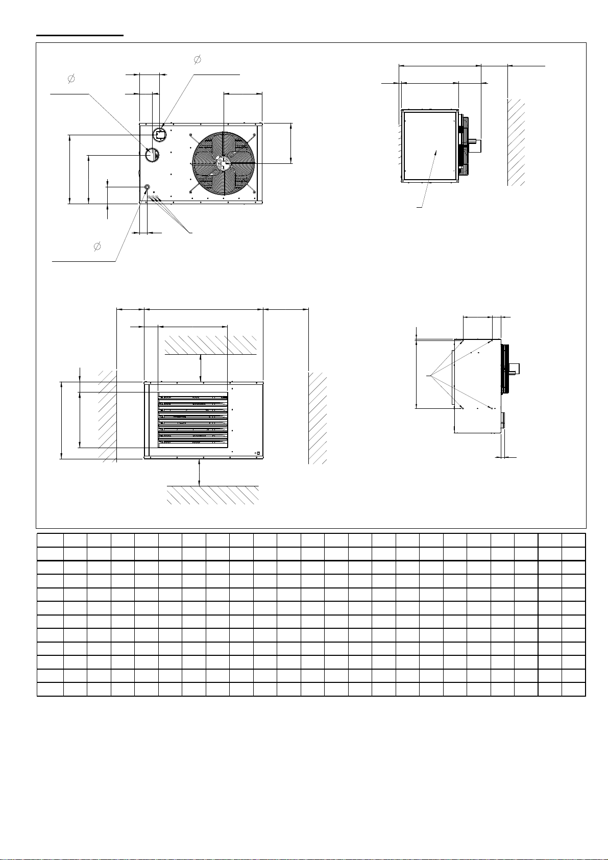
LCSA ABCDEFGH I JKLMNPQRSTUVW
12-3 965 567 652 80 71 531 130 305 100 782 334 280 87 106 345 444 122 221 123 611 406 1/2"G
20-3 965 567 652 100 71 531 130 305 103 785 334 280 87 106 345 444 122 221 123 611 406 1/2"G
30-3 965 567 652 100 74 531 94 370 139 821 334 280 87 106 345 444 122 221 123 611 406 1/2"G
35-3 965 845 652 130 74 531 154 517 142 824 331 420 82 175 508 720 134 211 123 611 406 3/4"G
45-3 965 845 652 130 74 531 117 605 142 824 331 420 82 175 508 720 134 211 123 611 406 3/4"G
50-3 1298 845 652 130 151 759 154 517 156 838 409 425 82 175 508 720 135 212 123 942 406 3/4"G
60-3 1298 845 652 130 151 759 154 517 142 824 409 425 82 175 508 720 135 212 123 942 406 3/4"G
75-3 1298 845 652 130 151 759 117 605 142 824 409 425 82 175 508 720 135 212 123 942 406 3/4"G
100-3 1298 954 807 130 151 759 73 808 185 1022 479 477 82 180 608 833 212 212 123 942 550 3/4"G
120-3 1750 980 846 130 67 1100 164 602 181 1057 348 490 90 175 595 795 160 256 20 1365 770 3/4"G
145-3 1750 1150 846 130 67 1100 173 692 181 1057 348 570 90 177 736 936 160 256 20 1365 770 3/4"G
2.2 Dimensions
K
L
S
R
N
M
P
Q
D
Flue Outlet
D
Flue Inlet
W
Gas Connection
1
250 min
J
I
C
30
2
F
150
150
E
150
A
500 min
GH
B
T
V
19
U
51
3
1 Electrical connections
2 Service panel
3 Suspension points (M10 female)
7/25
LCSA-3 12->20 30->50 60->145
Mounting height 3 4 5
GENERAL REQUIREMENTS
3.1 Related documents
It is important that all gas appliances are installed in
accordance with the rules in force and by
appropriately qualified persons. Failure to install
appliances correctly could lead to prosecution. It is
in your own interest and that of safety to ensure
compliance with the law.
3.2 Heater location
The location chosen for the air heater must permit
the provision of a satisfactory flue system venting to
outdoor atmosphere and adequately ventilated to
provide for combustion air. The location must also
provide sufficient space to allow the heater to be
serviced.
Table 3
Minimum installation clearances (mm)
LCSA-3
Top 150
Flue connector 150
Access panel 800
Non access side 150
Bottom 150
Rear* 450
*Measure rear clearance from the back of the motor
Table 4
Recommended mounting heights to underside (m)(*)
*Height from floor to bottom surface of heater. These are
recommendations only. Positioning of heaters depends on
application.
Air heaters should, where ever possible always be
installed to blow toward or along external wall
surfaces. Where two or more air heaters are
installed in the same room, a general scheme to
ensure continuous air circulation should be
maintained for best results.
Suspended heaters are most effective when located
as close to the occupancy zone as possible, this
fact should be born in mind when determining the
mounting heights to be used. Care should be
exercised to avoid directing warm air directly onto
the occupants. Partitions, columns, counters,
storage racking, etc. should be taken into account
when choosing the location so that an unobstructed
path for the air circulation can be maintained.
Where air heaters are located in the centre of the
space to be heated, the air should be discharged
toward outside walls. In large areas, they should be
located to discharge air along outside walls with
additional heaters provided to blow air into the
centre of the area.
In places where infiltration of cold is excessive,
such as entrance doors it is desirable to locate a
heater so that warm air is discharged directly
toward the source of cold air from a distance of 4,5
- 6,0m
Air heaters should not be installed in
corrosive atmospheres, i.e. near plating
or degreasing plants or in areas where
there is a fire risk.
Do not locate the air heater where it may
be exposed to water spray, rain, etc.
3.3 Combustion air supply & flue
system
The air heater may be installed as a balanced flue
(Type C) heater requiring both a combustion air
inlet duct and a flue pipe or as a power vented
(Type B) heater, which requires only a flue pipe
exhausting to outdoors. All products of combustion
must be flued to outdoor atmosphere.
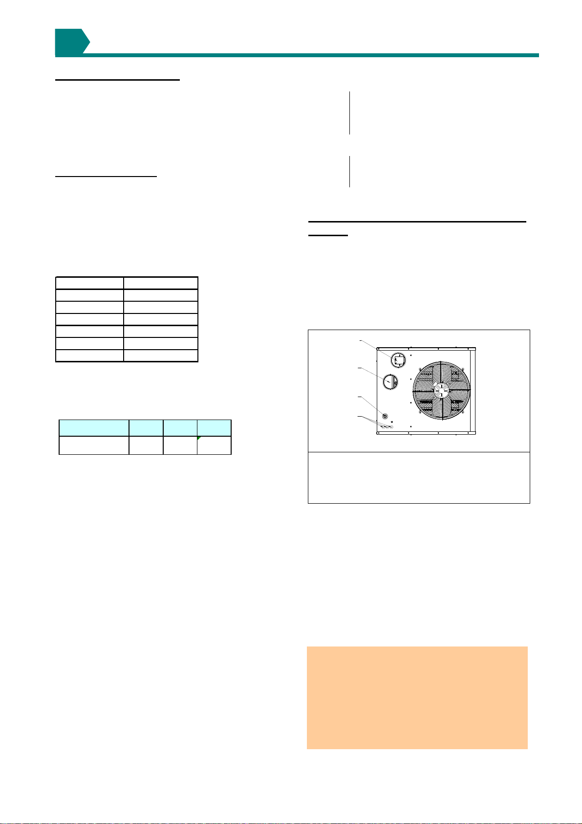
Figure 2a : Combustion air and flue pipe sockets
1
2
3
4
Legend :
1 Flue outlet socket
2 Combustion air inlet opening
3 Gas connection inlet with sealing ring
4 Electrical connections
Each heater installed as a type B appliance must be
fitted with an individual flue pipe and the
combustion air inlet opening must be provided with
a protection grill (ask your distributor for the
appropriate protection grill (IP20) (dia130 = PN 02
25094 ). Each heater installed as a type C
appliance must be fitted with an individual
combustion air/flue pipe system. Only systems
specified by the air heater manufacturer may be
used.
Common flue and combustion air systems must
not be used
IMPORTANT: The flue must be installed in
accordance with national and local regulations.
Failure to provide proper flueing could result in
death, serious injury and/or property damage.
The air heater must be installed with a flue to the
outside of the building. Safe operation of any
power vented gas apparatus requires a properly
operating flue system, correct provision for
combustion air, and regular maintenance and
inspection.
3

8/25
LCSA-3 12 35,45,50,60,75
100,120,145
Heater socket & mm
pipe dia
Maximum straight m
length
Equivalent length m
of 45° elbow
Equivalent length m
of 90° elbow
20,30
100 130
9
0.75
1.5
80
3.3.1 Flues for power vented installations
(Type B appliances)
If the air heater is to be installed as a type B
appliance, air for combustion will be taken from
within the space where the heater is installed.
Ensure that an adequate air supply for combustion
and ventilation is provided within the building in
accordance with the regulations & rules in force.
Table 5 shows flue pipe sizes and maximum pipe
lengths. The minimum flue length is 0.5 metres.
Table 5 Flue pipe diameters & maximum lengths
Single wall flue pipes are required. All joints must
be sealed to prevent products of combustion from
leaking into the building. An approved flue terminal
is required.
If the flue passes through a combustible element of
the building it must be enclosed by a sleeve of non-
combustible material and separated from the sleeve
by at least a 25 mm air break. The temperature of
any combustible material near to the flue must not
exceed 65°C when the heater is in operation. The
flue must be at least 50 mm away from any
combustible material.
Single wall flue pipe exposed to cold air or run
through unheated areas must be insulated. Where
condensation is unavoidable, provision must be
made for the condensation to flow freely to a point
to which it can be released, i.e. a drain or gully. The
condensation drain from the flue must be
constructed from non-corrodible material not less
than 20 mm diameter. Copper or copper based
alloys must not be used for condensation drains.
3.3.2 Combustion air inlet pipe & flue pipe for
balanced flue installation (Type C appliances)
Balanced flue air heaters are designed to be fitted
with a combustion air inlet pipe that obtains outdoor
air and a flue pipe that exhausts flue products to
outdoors.
Air heaters if fitted with a power venter permitting
either a vertical or horizontal combustion air
inlet/flue pipe system. The heaters must be
installed with a concentric vertical or horizontal
flue/combustion air inlet. The heaters are only
approved for use when installed with the
appropriate approved concentric vent terminal.
See table 6.
Both the flue and combustion air pipes must be
sealed. Use gasket sealed seamless aluminium pipe or
equivalent.
The flue pipe must include a re-sealable test port to
allow good average sampling of the flue gas mixture
for testing, the port must be at least 450 mm away
from the air heater flue connection socket.
Follow any flue pipe manufacturers’ installation
instructions for making joints, including connections to
the air heater, for passing through a building element
and for support requirements. If more than one air
heater is being installed in the same place each heater
must have a separate flue system.
Where condensation is unavoidable, provision must
be made for the condensation to flow freely to a
point to which it can be released, i.e. a drain or
gully. The condensation drain from the flue must be
constructed from non-corrodible material not less
than 20 mm diameter. Copper or copper based
alloys must not be used for condensation drains.
Figure 2b :
Combustion air and flue pipe sockets, Type C
Legend :
1 Flue products flue outlet socket for flue pipe
2 Combustion air inlet opening
Table 6
Combustion air inlet & flue pipe requirements
LCSA-3 12
Flue pipe 80
Inlet pipe 80
Flue pipe
Inlet pipe
Flue pipe
Inlet pipe
Flue pipe
Inlet pipe
Concentric vertical vent or wall terminal : Mugro/Burfix dia 130
Concentric horizontal vent or roof terminal : Mugro/Burfix dia 130
Equivalent length
of 45° elbow
Equivalent length
of 90° elbow
m
m1,5
1,5
Heater socket
& pipe dia mm
Max. straight
length m
20, 30 35 -> 145
100
100 130
130
9
9
0,75
0,75
9/25
3.4 Air supply
It is important to ensure that there is an adequate
air supply at all times for both combustion and
heating requirements. Modern constructions involve
the greater use of insulation, improved vapour
barriers, and weather proofing. This practice means
that buildings are sealed much tighter than in the
past.
The combustion air supply for a power vented gas
fired air heater (Type B installation) can be affected
by lack of air supply. Natural infiltration may not be
adequate. Use of extract fans aggravates this
situation. It is important to ensure that there is an
adequate air supply at all times. Reliance on doors
and windows is not allowed. Always ensure that an
adequate inlet for fresh air for combustion is
provided sized to suit the total installation of any
combustion apparatus.
Fit an access guard to the combustion air inlet on
the back of the heater and take appropriate action
to ensure that it remains unblocked. See figure 2c.
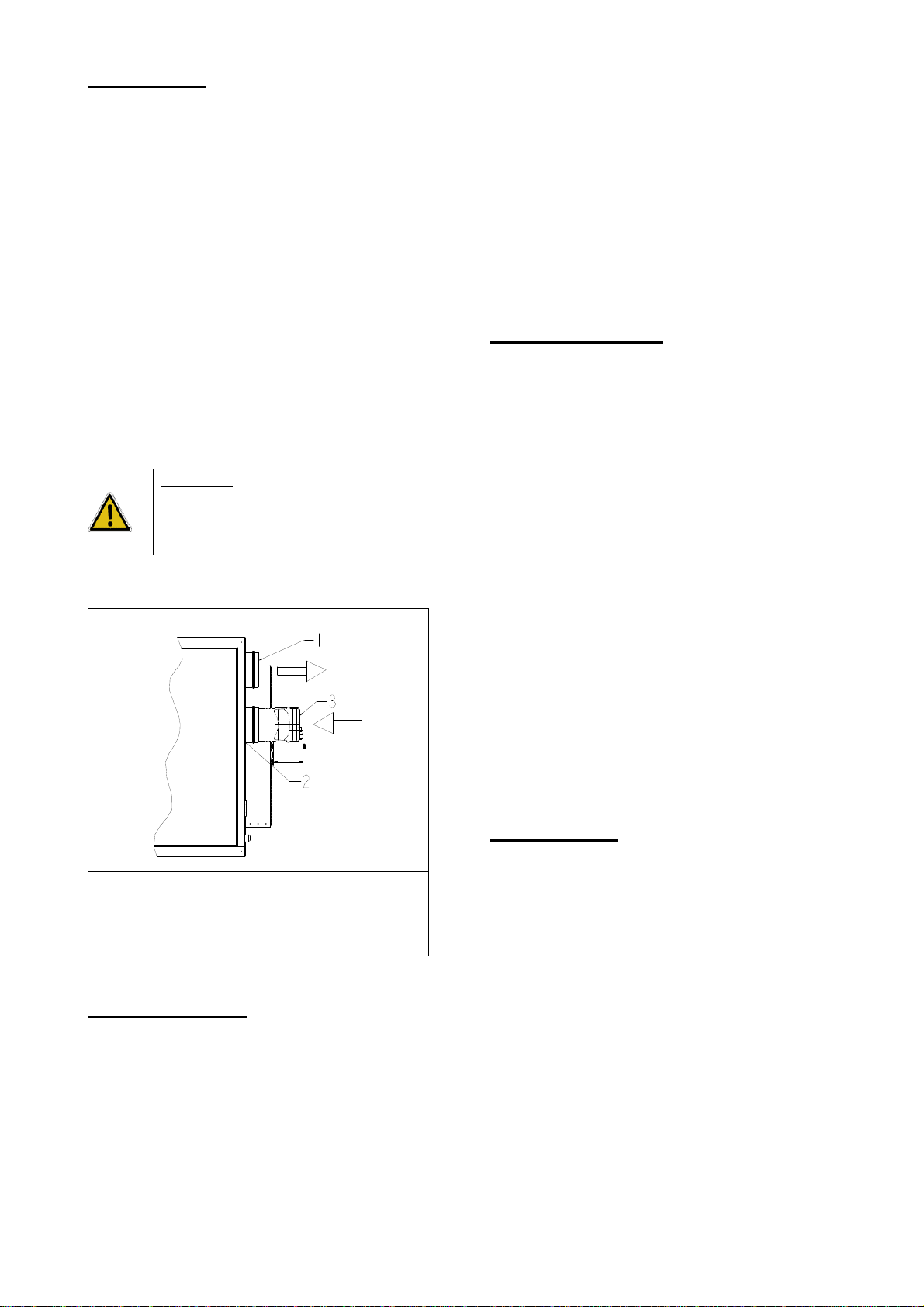
WARNING: This model air heater is
installed as a type B application and is
designed to take air for combustion from
the space in which it is installed. Do not
restrict the combustion air intake.
Figure 2c :
Combustion air and flue pipe sockets, Type B
Legend :
1 combustion products flue outlet socket
2 combustion air inlet opening
3 Protection grill (option) (PN 02 25094)
3.5 Air distribution
Follow recommended practice for building air
distribution.
The following notes are of particular importance:
"Where free blowing air heaters are installed it must be
taken into account that heated air is buoyant when it
leaves the appliance, therefore, air patterns within the
space being heated will modify the air throw pattern
achieved.
In building having low heat loss where single heaters
are required to cover a large floor area and in buildings
with high ceiling heights, air re-circulation fans e.g.
Maximizors may be fitted to ensure even heat
distribution and minimize stratification. Care should be
taken to avoid impeding air flow with storage racking,
partitions, etc."
3.6 Electrical supply
Wiring external to the air heater must be carried out
in accordance with the rules if force and by
appropriately qualified persons.
A constant 230 Volt 50 Hertz single phase fused
electricity supply with neutral link is required. All
heaters and controls must be earthed. A lockable
isolator with contact separation of at least 3.0 mm
on all poles should be installed adjacent to the
appliance and within reach of any person working
on the heater.
When a number of heaters are to be connected as
part of a single installation each heater must be
provided with a separate isolator.
The electrical connection to the air heater is at the
back of the appliance. The final connection must be
made in the terminals provided in the control
compartment. Follow the wiring diagram provided
with the air heater.
Electrical supply cable conductor size should be 1.5
mm. Fit the cord grip supplied with the heater. The
length of conductors between the cord grip and the
terminals must be such that in the event that the
cable becomes taut the line conductors do so before
the earth conductor.
3.7 Gas supply
LCSA-3 air heaters are designed to operate on
either natural gas (G20) or propane gas (G31).
Refer to the specifications in section 2 of this
document and to the data plate for details of supply
pressures.
The gas meter and gas service must be checked by
the supply undertaking to ensure that they are
adequate to deal with the total load of all gas fired
apparatus installed.
10/25
LCSA-3 12
20 30 35 45 50
60 75 100 120 145
Weight 59 64 94 99 114 126 184 242 279
INSTALLATION
4.1 Unpacking and preparation
Prior to dispatch, the air heater was operated and
tested at the factory. If the heater has incurred any
damage in shipment, file a report claim within 2
working days from receipt.
Check the shipping label and data plate to ensure
the specification of gas and electrical supplies are
compatible. Read this document and become
familiar with the installation requirements and the
appliance before commencing installation.
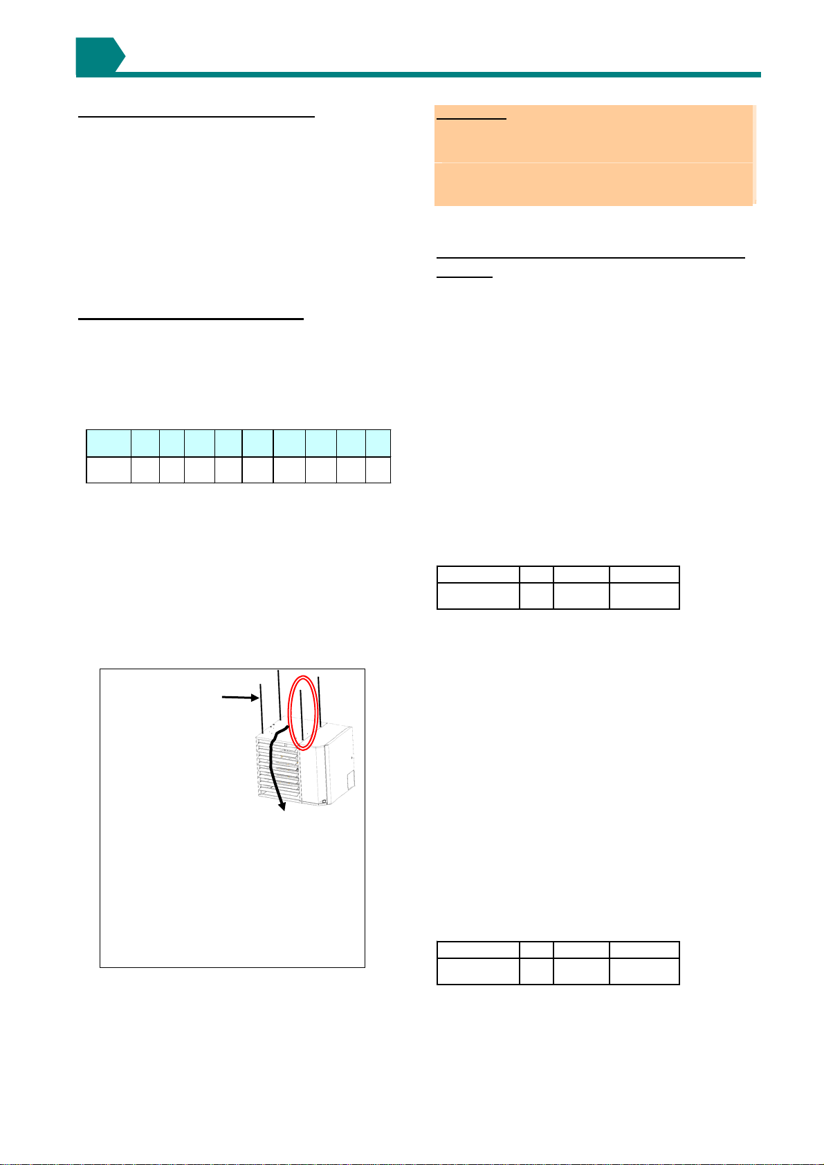
4.2 Suspending the air heater
Before installing the appliance, check to ensure that
the supporting structure is adequate to carry the
weight of the appliance and its ancillaries i.e. flue
system.
Table 7 Approximate Net weights (kg)
When the heater is lifted for suspension, support
the bottom of the heater with plywood or other
appropriately placed material. If the bottom is not
supported, damage could occur.
The heater is supplied with four point suspension.
All points must be used. Two threaded nut retainers
are provided on each side of the top of the heater.
See dimensions in section 2.2 and figure 3.
Figure 3 Suspension detail
Add a nut to lock the
M10x1.5 hanger rod to
the heater
Be sure that the threaded hanger rods are locked to the
heater as illustrated. Recommended maximum hanger
rod length is 1.8m.
IMPORTANT:
Suspend the heater from the threaded nut retainers. Do
not suspend from the heater cabinet panels.
Do not place or add additional weight to the suspended
air heater. See hazard levels, page 2.
The heater must be installed in a level plane to ensure
proper operation.
4.3 Fitting the Combustion air inlet/Flue
system
Flue pipe runs may be horizontal or vertical and
terminate either through the wall or roof. See table
5 for maximum pipe length for an appliance installed
as type B or table 6 for maximum lengths and
approved supplied concentric terminals for a heater
installed as a type C appliance.
All pipe runs must be independently supported so
that the heater does not carry any of the weight of
the flue system.
4.3.1 Fitting the flue pipe
The flue pipe socket is located on the back of the
air heater.
Flue pipes must be sealed. Use seamless,
aluminium pipe or equivalent. Follow pipe
manufacturer's instructions (see figures 4 & 5).
Table 8 Flue pipe socket size (dia mm)
12 20,30 35 -> 145
80 100 130
LCSA-3
Socket
4.3.2 Installing a guard on the combustion air
inlet pipe for power vent (Type B installations)
The combustion air inlet socket is located at the
back of the heater. When installed as a type B
appliance, protect the inlet by fitting an access
guard on the socket. Do not block this socket as it
supplies combustion air for the burner (see
figure 4).
4.3.3 Fitting the combustion air inlet pipe for
balanced flue (Type C installations)
The combustion air pipe attaches directly to the
inlet socket at the back of the heater. Air inlet pipes
must be sealed. Use seamless aluminium or
equivalent. Follow the pipe manufacturer's
installation instructions. See typical installations in
figure 5.
Table 9 Air inlet socket size (dia mm)
12 20,30 35 -> 145
80 100 130
LCSA-3
Socket
4

11/25
Figure 4
Figure 5
4.4 Gas connection
Connection to a gas network may only be carried
out by appropriately qualified persons. The gas
installation must comply with the rules in force
using materials appropriate for gas installation.
To facilitate servicing, the air heater must be fitted
with an approved gas service tap and union fitting
or union tap adjacent to the appliance.
The inlet gas supply line must be installed so as to
permit the access door to be opened and to allow
removal of the slide out burner assembly.
Air heaters suspended by flexible suspension
materials or drop rods must be connected to the gas
supply using an approved flexible connector.
Sufficient slack must be provided in the connection
to allow for movement of the appliance. Use a
flexible connector of suitable size to reduce the
pressure drop and the possibility of gas flow noise.
Do not use the appliance gas supply to
balance or support any part of the
appliance.
Figure 6
Legend :
1 Gas tube inlet sealing ring
2 Inlet gas pipe
3 Union fitting
4 Gas service tap
5 Gas pipe
4.5 Electrical connections
The electrical installation may only be carried out by
appropriately qualified persons observing the rules
in force.
All electrical connections should be made in the
heater control compartment (refer to figure 9).
Screw type terminals are provided. Connections
should be in accordance with the terminal markings
and the wiring diagram affixed to the air heater or
included with this document.
THIS APPLIANCE MUST BE EARTHED!
ATTENTION : Failure in electrical wiring can
bring real damage to components of this
appliance. Please follow very carefully the
wiring diagram supplied with this air heater.
The minimum external controls required for the air
heater are a room thermostat. It is essential the
main input line and neutral to terminals L and N
remains live at all times even when the appliance
is switched off this is to ensure correct
operation of the unit.
An indicator light and burner reset button are fitted
inside the appliance. To add a remote reset button,
make connections to the terminals in the electric
box as indicated on the wiring diagram.
IMPORTANT:
If the reset button requires activating for any reason the
cause should be identified before resetting. After
resetting stay with the appliance for long enough to
ensure that lock-out does not reoccur (suggest 5
minutes).
Fix all electric cables and installer’s wiring to the control
panel and ensure they do not touch the combustion
collector box.
danger

12/25
4.6 Room thermostat location
Do not attempt to control more than 1 air heater
from a room thermostat or control panel unless
a properly wired relay is fitted. Follow
instructions supplied with such panels.
The location of the room thermostat is important. It
should not be fitted on an outside wall. Avoid
location in draughty areas or where it may be
influenced by heat
sources e.g. the sun, process plant, etc. The
thermostat or temperature sensor should be
mounted on a vibration free surface and mounted
about 1,5 meters above floor level. Follow the
thermostat manufacturers fitting instructions. The
thermostat must be suitable for switching 230 volts.
AIR DISTRIBUTION
LCSA-3 air heaters are fitted with adjustable
horizontal louvers over the range 0 - 45 degrees
from the horizontal so as to be able to direct the
airflow downwards.
DO NOT ADJUST THE LOUVRES BEYOND THEIR
STOPS.
COMMISIONING & TESTING
The commissioning and testing may only be carried
out by appropriately qualified persons.
This section should be read and fully understood
before commencing commissioning and testing.
6.1 Electrical check
After completion of the installation and before
switching on the electrical supply to the appliance, a
preliminary check must be carried out by a qualified
electrician. The following must be checked:
* Ensure that all cables & installer’s wiring are
fixed to the gas pipe & that they do not touch
the combustion collector box
* Check that all wiring is connected in
accordance with the appliance circuit diagram;
* Ascertain that the correct fuse value and cable
size has been provided;
* Check to ensure that the appliance is earthed
by conducting an earth continuity test. Connect
a test meter, one lead to the appliance earth
terminal and the other to the mains incoming
earth point at the electrical isolator. A
resistance reading of 1,0 ohm or less must be
indicated. If a higher reading is obtained,
check all cable connections to ensure
adequate security and cleanliness. If problem
still exists , it may be necessary to consult the
electricity supply undertaking;
* Carry out a polarity test. Connect one lead of a
suitable AC voltmeter to earth and connect the
other lead to the live supply terminal (L) at the
air heater. Switch ON the power to the air
heater and check for correct voltage.
The same result should be obtained by
connecting the test leads between live and
neutral.
Connect the voltmeter test leads to N and E. A
reading of 0V should be obtained. If these
tests do not conform to the above, there is a
fault which must be rectified before proceeding
further with the commissioning;
* Check that a suitable thermostat or control
panel has been fitted;
* Ensure that an electrical isolator with two pole
separation with a minimum air break between
poles of 3,0 mm has been fitted adjacent to the
air heater.
6.2 Gas connection
Only persons formally qualified to work on gas
fired apparatus may carry out commissioning
and testing.
The whole of the gas service installation including
the
meter must be inspected, tested for soundness and
purged in accordance with appropriate requirements
by a qualified person.
Never use a flame for checking gas
soundness.
5
6
13/25
6.3 Suspension and support
Check to ensure that the air heater is adequately
suspended or supported and that no other parts have
been fitted that are not independently supported and
secured. For safe and correct operation, check the
heater is level in both planes.
6.4 Lighting the air heater
LCSA-3 air heaters are all fitted with automatic spark
ignition systems. When adequate airflow for
combustion is proven by an air proving control and a
pre-purge period has elapsed, the integral ignitor
and multi-functional gas control operate. The ignition
spark ignites the gas creating the burner flame which
is detected by a flame rod sensor. If a burner flame
is not detected, the ignition controller proceeds to
lock-out and requires manually resetting. Lock-out is
indicated by the red warning light on the air heater.
Note : If the first reset is not successful, wait 15
seconds before attempting reset.
6.4.1 To turn the air heater "ON"
The following checks should be carried out before
attempting to light the air heater.
* Ensure that the gas supply to the air heater is
turned ON;
* Ensure that the electrical supply to the air heater
is switched ON;
* If fitted ensure that a time switch is set to an ON
period
* Set room thermostat to call for heat. e.g. to above
room ambient temperature. The burner will now
light.
The burners can be seen through the viewing port.
* Adjust the room thermostat to the required
operating comfort temperature. The air heater will
now start automatically when heat is called for by
the room thermostat.
Note : If the air heater will not start on initial start-up,
the ignition controller may be in lock-out position and
require resetting. This may occur especially if the
appliance has been on stand-by for a prolonged
period.
6.4.2 To turn the air heater "OFF" for short
periods
Adjust the room thermostat to its lowest setting or
'OFF'. The fan will continue to run to cool the heater
and then switch OFF automatically.
6.4.3 To turn the air heater "OFF" for long
periods
Adjust the room thermostat to OFF or its lowest
setting. When the fan has stopped, turn OFF the
gas supply and then switch OFF the electricity
supply to the air heater.
6.5 Air heater gas pipe work
The soundness of the air heater pipe work has been
checked prior to leaving the factory. However during
installation, connections may have been loosened.
Check the soundness of the appliance pipe work
using a soapy solution. If any leaks are found they
must be rectified immediately.
Never use a flame for checking gas
soundness.
6.6 Adjustments
6.6.1 Burner gas pressure adjustment
The gas pressure is set for the required heat input
before the appliance leaves the factory. Provided
the gas supply to the air heater is in accordance
with the supply pressure described on the appliance
data plate the operating pressure will not require
adjustment. To check the pressure, the following
procedure should be carried out:
* Ascertain from section 1 of this document and
the appliance data plate the correct operating
gas pressure for the air heater;
* Turn the room thermostat control to its lowest
setting;
* Remove the screw from the burner pressure test
point of the multi-functional control valve.
Connect a manometer to the test point( see
figure 7);
* Adjust the room thermostat to call for heat e.g.
above room ambient temperature;
* Observe the burner gas pressure on the
manometer and compare to the required
pressure;
* If necessary, adjust the burner gas pressure
(only for natural gas). Remove the cover screw.
Turn the regulator screw anti-clockwise to
decrease pressure or clockwise to increase
pressure (see figure 7);
* Set room thermostat to lowest setting to turn the
burners OFF. Replace the test point screw (if
removed) and with the main burner alight, test
for gas soundness using a soapy solution.
Reset temperature control/room thermostat to
comfort operating level.

14/25
LCSA-3 Normal
equilibrium
warm (Pascal)
Set point
'off'
(Pascal)
12-3 >131 119
20-3 >163 135
30-3 >170 130
35-3 >200 155
45-3 >183 155
50-3 >183 155
60-3 >240 175
75-3 >290 185
100-3 >250 210
120-3 >250 238
145-3 >250 238
at 2x1mpipe with terminal
Figure 7 : Honeywell gas valve
Legend :
1 Gas valve HONEYWELL VR4601AB
2 Inlet pressure gas test point
3 Burner pressure gas test point
4 Burner pressure regulator cover
5 Burner pressure regulator
6 Electrical connection 230V
6.7 Air distribution system
Adjust the air outlet discharge louvres to provide a
satisfactory spread of the warm air. Direct the air
towards the floor avoiding blowing directly on people
who may be in the vicinity of the appliance.
If louvre adjustment is carried out whilst
the appliance is hot wear gloves to avoid
being burnt.
6.8 Air heater controls and operation
Check air heater operation after all adjustments have
been carried out. Set the temperature control above
ambient temperature.
LCSA-3 air heaters are fitted with a pressure
sensitive, combustion air safety control that monitors
the combustion airflow.
The control operates with the settings given in table
10 (settings are for sea level installations)
When the combustion air safety control closes,
verifying airflow, the gas control valve will open and
the burner will light. When insufficient airflow, the
burner will extinguish until the airflow returns to the
acceptable level.
Wait approximately 30 seconds after the burner has
lit, the time delay relay will activate the thermal fan
control which will energize the fan motor. Continue to
operate the air heater for several minutes to ensure
correct operation.
Turn room thermostat to its lowest setting. The main
burners should extinguish while the fan continues to
run to cool the air heater. The fan delay relay will
normally be de-energized and stop the fan motor in
approximately 45 seconds.
Table 10 Combustion air pressure control settings
6.9 Handing over
Upon satisfactory completion of commissioning and
testing, hand the instructions to the user or their
representative.
Advise the appropriate person how to safely use
and operate the air heater and describe the use of
appropriate external controls. Ensure that the
person understands how to start the heater and how
to turn it OFF.
Suggest that the instructions are placed close to the
air heater for future reference. In the absence of an
appropriate location fix them to the gas service
meter. Ensure they are not placed where they may
restrict the airflow from the heater or where they
may catch fire from a hot surface.
Advise the person who is resuming responsibility
that for continued safe operation the air heater
should be serviced at least once a year.

15/25
SERVICING INSTRUCTIONS
IMPORTANT:
Only appropriately qualified persons may carry out
servicing and fault finding on this gas fired equipment.
Before commencing service ensure that both the gas and
the electricity are turned and switched "OFF" and that
the air heater has cooled down. Inadvertent substitution
or replacement of components similar to those specified
or replacement in a manner contrary to the method
herein described could constitute a hazard and lead to
prosecution.
When cleaning air heaters, wearing of eye
protection and a dust face mask is
recommended.
LCSA-3 air heaters will operate with a minimum of
maintenance. To ensure long life and satisfactory
and safe performance, an air heater that is operated
under normal conditions should be inspected and
cleaned at the start of each heating season. If the
air heater is operated in an area where unusual
amounts of dust, etc are present in the air, more
frequent servicing is recommended.
When any service is completed, be sure that
components are reassembled correctly to ensure
that no unsafe condition exists.
Upon completion of the service carry out the
commissioning instructions outlined in section 6 of
this document.
WARNING: Excessive dirt build-up on the
inside of the burner ports could cause
unburnt gas to spill out of the back of the
burner tube causing a fire or explosion.
To prevent this occurring, clean all of the
burner ports at least annually.
Service procedure
The following procedures should be carried out at
least annually:
1. Remove the burner assembly as in section 8.1.
Clean thoroughly, (cleaning the burners requires
an emery cloth, wire brush and a cleaning cloth -
stubborn deposits on burners are best cleaned
using "acetone" as a solvent).
* Check the condition of the ignitor and clean to
remove all deposits. Check the spark gap (3,0
mm).
* Check the sensor - clean as necessary.
* Remove any soot deposits from the burner with
a wire brush. Clean the ports with a degreaser
or acetone. A vacuum cleaner or compressed
air may assist in this cleaning operation. Wipe
the
inside of the burner tube clean (cleaning
thoroughly with a degreaser as recommended
will retard future build-up of dirt). Inspect the
burner for any damage or deterioration. If the
burner is damaged or corroded, replace it.
2. The heat exchanger should remain clean unless
a problem has developed due to poor
combustion. Examine the heat exchanger tubes
internally and externally for any sign of
deterioration. The outside of the tubular heat
exchanger can be cleaned from the front of the
heater with an air jet and/or a flexible brush.
Remove any dust and grease deposits.
The inner surfaces of the heat exchanger can be
reached for cleaning with the burner and
combustion air fan (venter) assemblies removed.
Clean with a flue brush or a heavy wire to which
wire wool has been attached.
Brush inside each heat exchanger tube until all
foreign material has been removed. The use of a
flashlight is necessary to carry out this
operation.
3. Clean the axial fan blades, fan guard, and fan
motor to remove all external dirt . Check the
security of the fan on the motor.
Note: Fan motors are lubricated for life
and do not require lubricating.
4. Remove any dirt and/or grease that may have
accumulated on the venter fan motor and its
housing. NOTE: The combustion air fan motors
are lubricated for life and do not require oiling or
greasing.
5. The gas multi-functional control valve requires
no field maintenance except cleaning of its
exterior and checking the condition of the wire
connections. Instructions for testing pressure
are given in section 6.6.
6. Check the flue/combustion air system for
soundness. Reseal/replace any parts that are
not sound.
7. Check all wiring connections. Check wiring for
any signs of damage. Replace any suspect
wiring with an equivalent specification.
8. Check operation of thermal fan control and
control relay.
9. When service is complete carry out full
commissioning procedure as per section 6 of this
document.
7

16/25
Removal & replacement of parts
LCSA-3 air heaters must only be fitted with
authorized replacement parts. These heaters must
use certificated spare parts to comply with
legislation.
8.1 Main burner removal
Instructions for burner removal (see figure 8):
1. Turn OFF the gas supply to the air heater.
2. Switch OFF the electricity supply to the air
heater.
3. Open the access door.
4. Disconnect the union in the gas supply outside
of the appliance.
5. Remove gas supply pipe from multi-functional
gas control valve.
6. At the burner rack assembly, remove the nuts
that secure the burner manifold to the burner
rack. Lift the burner rack/manifold assembly
upward and pull the assembly out of the air
heater.
Instructions for re-assembly:
1. Reverse the procedure for removal making sure
that all parts are installed correctly. Check that
all components are secure.
2 When lighting, always follow the lighting
instructions on the air heater.
Remember!
After any service work has been carried out, the air
heater must be fully commissioned. See section 6
of this document
Figure 8 (for clarity, the heater cabinet & other parts
are not illustrated)
Figure 9 View of the Control Compartment
1
2
3
4
5
6
7
8
9
10
11
12
14
13 1 Burner
2 LC3 limit controls
3 Burner operating lamp H6
4 Reset switch S3
5 Spark igniter ER
6 Control panel
7 Gas valve V1
8 Fan motor M1
9 Venter motor M3
10 Fan control relay KFC
11 LC1 limit control
12 Flame sensor IS
13 Reset LC3
14 Fuse F3.1
8

17/25
8.2 Burner injectors
1. Carry out steps 1 to 6 of section 8.1.
2. Unscrew the main burner injectors.
3. Re-fit new injectors.
4. Re-assemble in reverse order.
8.3 Ignition system
To access the ignition system, follow steps 1 to 3 in
section 8.1.
Ignitor-refer to figure 9 and locate the ignitor (on
the side of the burner rack). Disconnect the wire,
remove the screw and the ignitor. Clean with an
emery cloth.
Note: Spark gap must be maintained to 3.0 mm (see
figure 10a)
Re-fit the ignitor as per figure 10b.
Due to high voltage on the spark wire and
electrode, do not touch when energized.
See hazard levels.
Flame sensor - Refer to figure 9 and locate the
flame sensor. Disconnect the wire, remove the
screw and the flame sensor. Clean with an emery
cloth.
Ignition controller - The enclosed integrated
circuit monitors the operation of the burner including
ignition. Do not attempt to dismantle the ignition
controller. Each heating season ignition cables
should be checked for insulation deterioration and
good connections.
Proper operation of the direct spark ignition
system requires a minimum flame current of 1,0
μA when measured with a micro-ammeter.
Fig. 10a - Ignitor assembly
Fig. 10b : Fitting the ignitor
For further information and checkout procedure of
the direct spark ignition system, refer to the
manufacturers control operating instructions a copy
of which is supplied with the air heater.
8.4 Multi-functional gas control valve
1. Ensure gas supply to the air heater is turned
OFF.
2. After the air circulation fan has stopped, switch
OFF the electricity supply to the air heater.
3. Mark for future identification and disconnect the
wires connected to the valve.
4. Disconnect the gas service union between the
control valve and the gas service tap. Remove
the gas control valve.
5. Re-fit a replacement valve making all of the
required connections.
6 Carry out complete commissioning procedure
prior to placing the appliance back into service
as outlined in section 6.0
The gas control operating valve is the
prime safety shut-off.
All gas supply lines must be free of dirt,
scale, etc. before connecting to the air
heater thus ensuring positive closure of
the control valve.
8.5 Thermal overheat (limit) controls
If it is determined that the thermal overheat control
needs replacing, use only authorized replacements
that are designed for this appliance.
To gain access to the control, open the controls
compartment access door. Refer to figure 9 for
control locations. The control near the top of the air
heater is a disc type control. Both controls are
capillary types with a capillary tube that extends
into the heat exchanger area. To remove the
controls, disconnect the wires leading to them,
remove the fixing screws and lift clear of the inner
casing panel.
Note: The capillary control is fitted to a bracket.
With the bracket removed from the air heater,
remove the control from the bracket.
When replacing a capillary control be careful not to
damage the capillary tube by kinking. Make bends
with a generous radius (approx 25 mm).
8.6 Combustion air control/switch
If it is determined that the air differential pressure
switch needs replacing, use only authorized
replacements that are designed for the air heater
being serviced. These switches are calibrated to
operate at the designed combustion air flow duty for
each appliance size in the product range.
8.7 Combustion air fan (venter)
1. Ensure gas supply to the air heater is turned
OFF
2. After the air circulation fan has stopped, switch
OFF the electricity supply to the air heater.
3. To gain access to the fan open the hinged
controls compartment access door. refer to
figure 9 for location
4. Mark for future identification and disconnect the
wires connecting the fan motor at the terminals
on the main wiring junction.
5. Remove combustion air fan and clean as
necessary using a wire brush and solvent to
remove sticky residues.
6. Re-assemble and check for free rotation before
proceeding to test the appliance.
Note : the combustion air fan motor is lubricated for
life. DO NOT OIL or GREASE.
18/25
FAULT FINDING
Fault finding may only be carried out by appropriately qualified persons
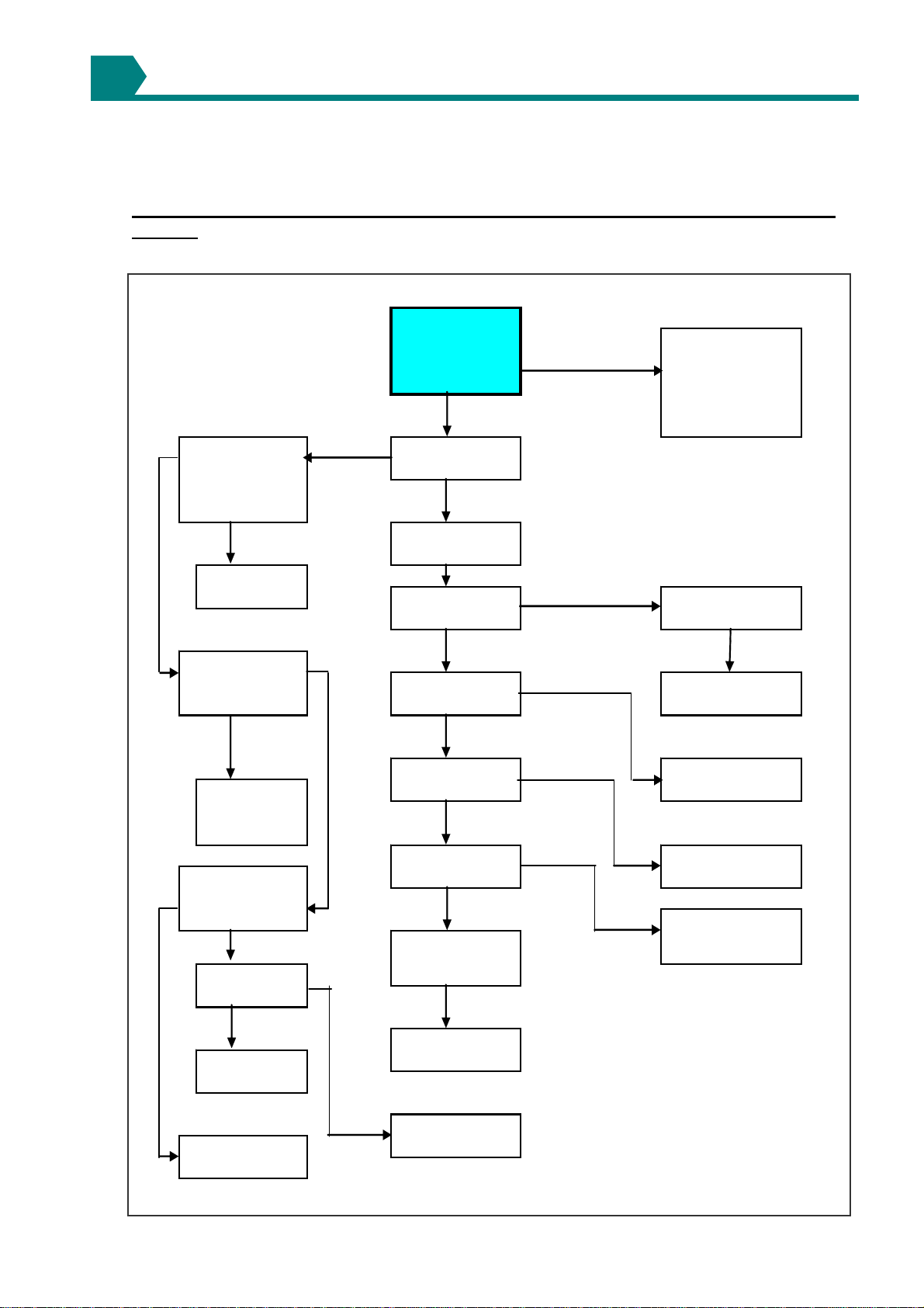
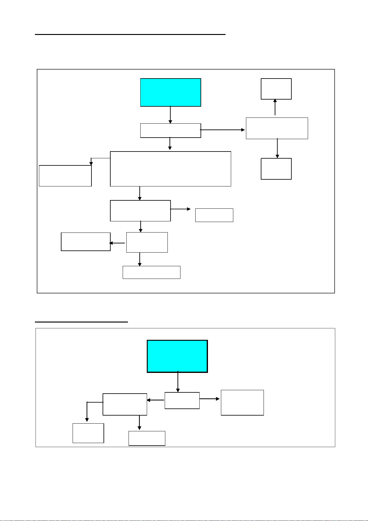
9.1 Main fault finding chart - Lock-out indicator light is "OFF", but air heater will not
operate
no
yes
yes
no
no yes
yes
no
no
yes no yes
no
yes
yes
no
no yes
no
yes
yes
Is there continuity between
terminals 9 &10
Check electronic
ignition control
Is there a restriction in the
flue pipe or inlet grill
Is the wheel dirty
Determine what caused the
limit to trip
Place into normal operation
Check the mains
Check the time/tempeature
control
Is there continuity between
9 & 10 ?
Is there 230V between
11 & 12 ?
Is power venting operating?
Reset limit control
Check venter motor
Replace pressure switch
Is the thermostat above
roomtemperature and if
used is the time
clock"ON" Set thermostat above room
temperature & if used make
certain the time clock is ON
Does the power venter
operate?
Is there 230V between
L&N?
Is there 230V between
1 & N ?
Check pressure switch
Connect or replace tubing
Correct fault
Is the pressure tubing
connected & in sound
condition?
Clean the venter wheel
9
19/25
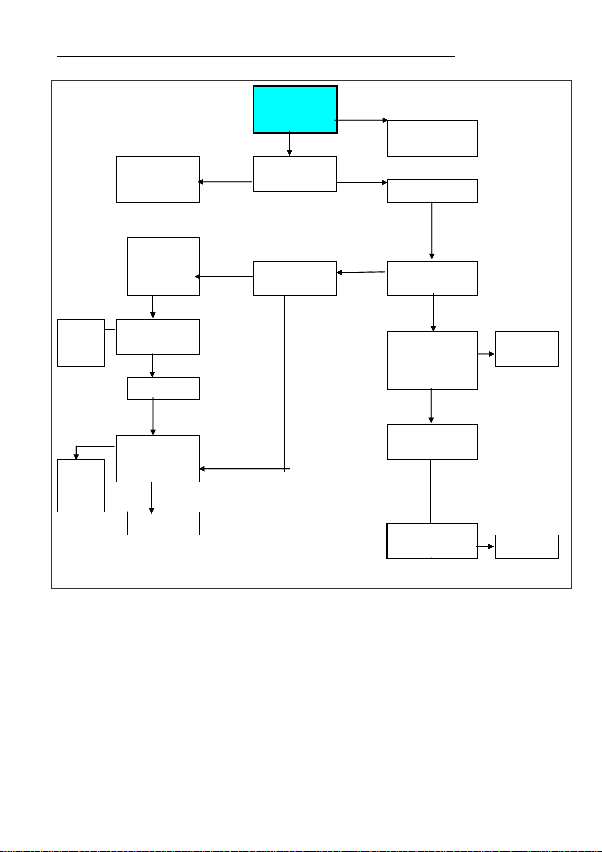
9.2 Ignition Controller Lockout indicator Light Repeatedly Comes "ON"
no
yes
no yes
no no
yes
no yes
yes
no
yes
no
yes
check
electronic
ignition
control
Place in normal
operation
check multi
functional
gas valve
Spark visible, still no
flame
Is there 220 to 240V
between terminals
13 & N
Check electronic
ignition control
correct the gas supply
pressure
During 5" trial for ignition
is a spark visible?
Check electronic
ignition control
Check spark gap and
ceramic & check
spark wire &
connector Is a spark visible ?
Check flame signal. Is it
greater than 1,0 micro
Amps?
Check flame signal using
micro amp meter. Is signal
greater than 1,0 micro
Amps?
During 5" trial for ignition is
a flame visible in ths view
port?
Correct polarity
Does the inlet gas
pressure agree with the
data badge
Is polarity of mains
correct?
Remove corrosion
& scale from flame
sensing rod & clean
ceramic insulation
Wait 15" and press
reset button
20/25
9.3 Limit Control Fault Finding Chart (limit control trips)
Note LCSA-3 air heaters are equipped with 2 limits (a recycling limit and a manual reset limit). During normal operation, neither limit should
trip even if the main electric supply is interrupted during operation. In the event of motor failure, the recycling limit will trip opening the gas
valve.
yes
no yes
yes no
yes
no no
yes
yes
no
Check for excessive
main burner pressure
Does the fan
motor operate?
Remove the
restricition
Has any non-factory authorized air distribution
device been placed on the heater? Is there excessive
static pressure in the ductwork? Did the motor overload
trip?
Does the fan control
energize the fan motor
in less than 75"?
Adjust thermostat
temp. setting above
ambient to energize fan
& gas solenoid valve
Replace
the motor
Consult fan
fault finding
Does the limit trip
before the fan is
energized?
Place system in normal
operation
Consult fan
fault finding
Is there 220-240V at
terminals N and 4?
9.4 Fan Fault Finding Chart
no no yes
yes
Adjust thermostat
temperature
setting above ambient to
energize the fan and the
fan solenoid valve
Does the fan
operate ?
Is there 220-240V
at terminals N & 4?
Replace the
fan start relay Replace fan
motor
Place the system
in normal operation
Table of contents
Other Nortek Global Heater manuals

Popular Heater manuals by other brands

Etherma
Etherma CIR Series Installation and operating instructions

Sentiotec
Sentiotec Concept R mini Series Instructions for installation and use

Ballu-Biemmedue
Ballu-Biemmedue GE 65 instructions

Universal
Universal 170-F owner's manual

BN Thermic
BN Thermic OUH3-40 instructions

Toyotomi
Toyotomi LC-43 instruction manual

Everwarm
Everwarm EWPO2430NV Owners operaion and installation manual

Ecostrad
Ecostrad ECO6+ user manual

Drazice
Drazice TJ 2" HP 9 kW OPERATING AND INSTALLATION Manual

Berko
Berko FRA series Installation & maintenance instructions

Adax
Adax VP9 Installation instruction

Dometic
Dometic TwinBoost4000 Installation and service manual


