North American Tool 8902 User manual

8808902 06/13
14/20 INCH CHAINSAW
CALIFORNIA PROPOSITION 65
WARNING: You can create dust
when you cut, sand, drill or grind
materials such as wood, paint,
metal, concrete, cement, or other
masonry. This dust often contains
chemicals known to cause cancer,
birth defects, or other
reproductive harm. Wear
protective gear.
WARNING: This product or its
power cord may contain
chemicals, including lead, known
to the State of California to cause
cancer and birth defects or other
reproductive harm. Wash hands
after handling.
Important!
When using equipment, a few safety
precautions must be observed to
avoid injuries and damage. Please
read the complete operating manual
with due care. Keep this manual in a
safe place, so that the information is
available at all times. If you give the
equipment to any other person, give
them these operating instructions as
well. We accept no liability for
damage or accidents which arise due
to non-observance of these
instructions and the safety
information herein.
SPECIFICATIONS
Engine Displacement: 45.1 cc
Bar Length: 14in. and 20in.
Idling Speed: 3000 RPMs
Max. Speed with Cutting
Equipment: 10,000 RPMs
Anti-Vibration Function
Chain Brake
Auto Chain Lubrication
CAUTION:
FOR YOUR OWN SAFETY READ
INSTRUCTION MANUAL
COMPLETELY AND CAREFULLY
BEFORE OPERATING THIS
CHAINSAW.
Any failures made in following the
safety regulations and and
instructions may result in an
electric shock, fire and/or serious
injury.
NOTE: Remove the 14”Bar and
Bar Cover from the bottom of the
case by unscrewing the anchor.
SAFETY INSTRUCTIONS
Only allow users who have read
and understand this manual
operate this chainsaw.
Wear protective gear, such as
steel-toed footwear, snugly fitting
clothing, heavy duty gloves, eye
protection (goggles or face
screen), hard hat and ear
protection (ear plugs or mufflers).
Do not wear jewelry and pull long
hair back.
Keep all body parts clear of the
chain while the engine is running.
Do not allow other people or
animals near the saw when it is
running, starting, or being
operated.
You must be mentally alert and in
good physical condition when
operating a chainsaw because the
work is strenuous
Carefully plan your sawing project
before starting. Do not begin until
you are sure the work area is
clean, you have secure footing
and if you are felling trees, that
you have a planned and clear
retreat path.
For Customer Service, please call 1-800-348-5004 or
email feedback@natitools.com 1
Model: 8902,
50969
2
KICKBACK
WARNING: Kickback is the
backward, upward or sudden
movement of the guide bar that
occurs when the guide bar contacts
an object or when the wood closes in
and pinches the saw in the cut. The
saw contacting a foreign object in the
wood can also result in a loss of
control.
Rotational kickback occurs when
the moving chain contacts an object
with the upper tip of the guide bar.
This can cause the chain to dig into
the object, which then stops the
chain for a moment. The result is a
reverse reaction, which kicks the
guide bar up and back towards the
operator.
Pinch kickback occurs when the
woods closes in on the moving chain
along the top of the guide bar. The
sudden stop of the chain results in
the saw to move in the opposite
direction of the rotation and the saw
is driven straight back towards the
operator.
Pull in occurs when the moving
chain comes in contact with a foreign
object in the wood along the bottom
of the guide bar. This sudden stop
pulls the saw forward and away from
the operator and could possibly
cause the operator to lose control of
the saw.
Avoiding Kickback
Be aware of situations or objects that
can cause the material to pinch the
top of or stop the chain.
Do not cut more than one log at a
time.
Do not twist the saw when the bar is
withdrawn from an undercut.
Always begin cutting with the engine
at full speed and with the saw
housing resting against the wood.
Use wedges made of plastic or
wood to hold the cut open. Never
use metal.
Stay alert. Realize kickback can
occur and keep the cutting area free
from foreign objects.
Keep your chain properly tensioned
and sharp, along with properly
maintaining the chainsaw. Failure to
do so can increase the chance of
kickback occurring.
Begin and continue the cut with the
engine running at full speed. Use
caution while re-entering a previous
cut. Do not attempt a plunge cut
(starting a cut with the tip of the
blade).
Maintaining Control of the
Chainsaw
Stand to the left of the saw. Keep
your elbow locked and a firm grip on
the saw.
Keep the thumb on the underside of
the handlebar. Never reverse hand
positions (left hand on handlebar
and right hand on the rear handle).
Stand slightly to the left side of the
saw to keep your body from being in
a straight line with the saw. Stand
with your weight evenly balanced
between both feet.
Do not overreach because you could
be thrown off balance and lose
control of the saw. Do not cut above
shoulder height because it is difficult
to maintain proper control of the saw
at that height.
Chain Brake
The chain brake is designed to stop
the chain from rotating in the event
of a kickback.
WARNING: DO NOT RELY UPON
THE CHAIN BRAKE (OR OTHER
SAFETY FEATURES) TO
PROTECT YOU IN THE EVENT OF
A KICKBACK. Use your chainsaw
properly and under the correct
circumstances to avoid kickback.
ASSEMBLY
Wear protective gloves at all times
during assembly due to the handling
of sharp objects.
Attaching the Bumper Spike
The bumper spike may be used as a
pivot when making a cut.
1) Loosen and remove the bar knob
completely by loosening the two
nuts.
2) Remove the clutch cover.
3) Attach the bumper spike with the
two screws with the spikes pointing
downward.
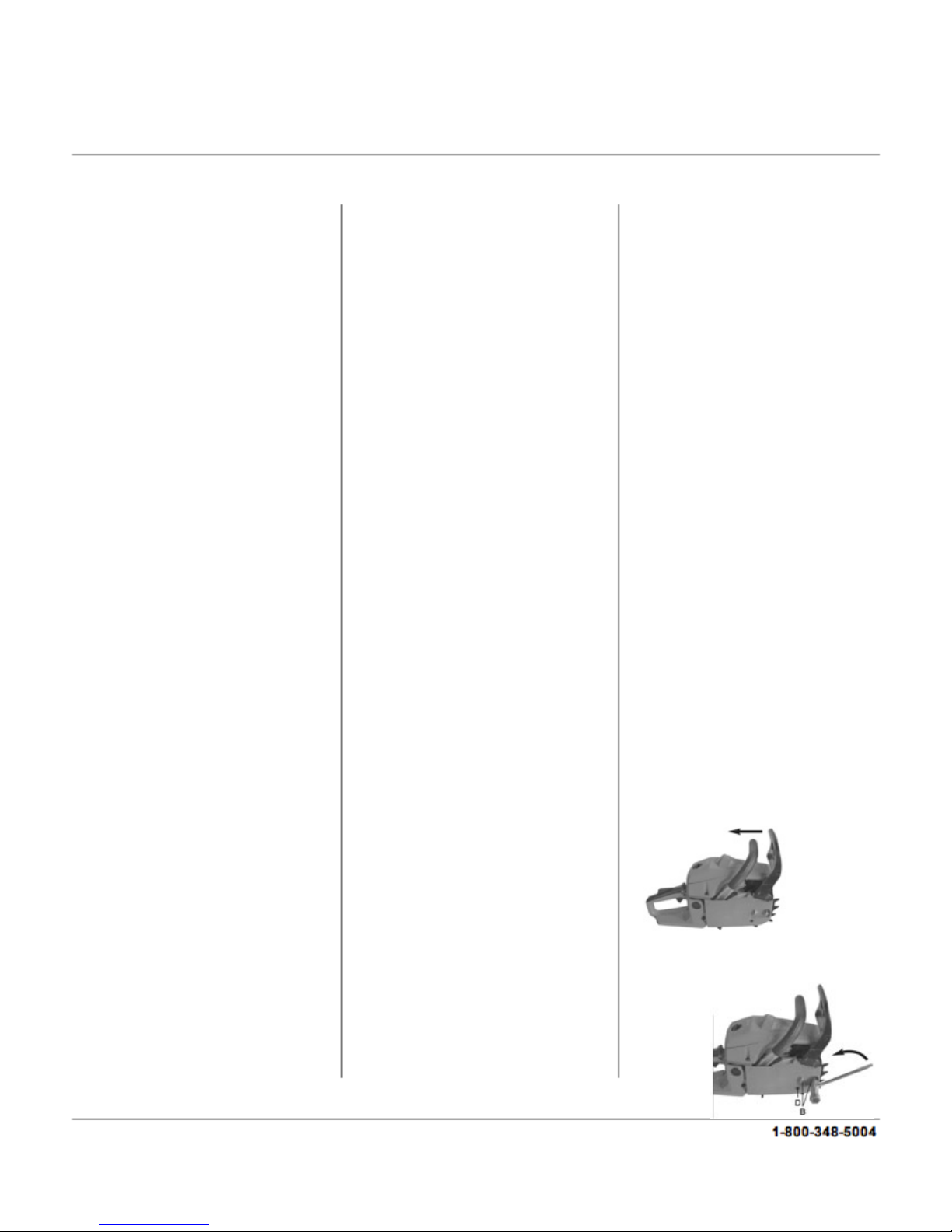
Attaching the Bar and Chain
1) Make sure the saw bottom is
resting on a flat surface. Be sure the
chain brake is pulled back. (Figure1)
Loosen and remove the bar knob
completely by removing the two
nuts. (Figure 2)
feedback@natitools.com
Figure 1
Figure 2

2) Remove the clutch cover.
(Figure 3)
3) Slide the guide bar on the bar
bolts until the guide bar rests against
the clutch drum sprocket. (Figure 4)
4) Hold the chain with the drive links
as shown. The drive links should be
facing inward with the cutters facing
to the right, or direction of rotation.
(Figure 5)
5) Fit the drive links in the clutch
drum sprocket. (Figure 6)
Figure 6
6) Place the chain drive links into the
bar groove.
7) Pull the guide bar forward to
make sure all of the drive links are in
the bar groove.
8) Reinstall the clutch cover. (Figure
3) Make sure the adjusting pin is
aligned with the hole in the guide
bar.
CAUTION: Make sure the
adjustment pin aligns with the hole.
Failure to align the pin and install the
cover properly may result in
damage, possibly permanent, to
your saw.
ADJUSTING CHAIN TENSION
Before adjusting, make sure the bar
knobs are loosened 1 ½- 2 turns.
Adjusting the chain tension with the
knobs tight can cause damage.
Checking the Chain Tension
Check the chain tension by using a
screwdriver to move the chain along
the bar. If it does not rotate, it is too
tight. If it sags below the bar, it is too
loose.
Adjusting the Chain Tension
The chain stretches slightly during
each use, especially the first few
times the saw is used. Always check
the chain tension each time the saw
is used and refueled.
1) Make sure the bar knobs are
loosened 1-1/2 –2 turns.
2) Using a screwdriver, adjust the
tension of the chain. The adjusting
pin is located right below the two bar
knobs.
3
3) Turn the screw to the right to
increase the tension and turn it to
the left to release tension.
4) Using a screwdriver, move the
chain around on the guide bar to
make sure all of the links are in the
bar groove. If the chain does not
rotate, it is too tight and the
adjuster needs to be loosened.
5) Tighten the bar knob securely
after the tension is adjusted.
FUELING AND LUBRICATION
Use regular grade unleaded
gasoline mixed with 40:1 2-cycle
engine oil. Do not use a fuel
mixture that has been stored for
more than 90 days.
The bar and chain require constant
lubrication in order to function
properly. Lubrication is provided by
the oiler system. Lack of oil will
cause damage to the bar and
chain. Smoke coming from the
chain and discoloration on the bar
are signs the oil is low.
Fueling Safety Instructions
1) Do not smoke while fueling or
operating the saw.
2) Do not allow sparks or flame in
the area where the fuel is poured or
mixed. Always allow the engine to
cool before refueling.
3) When refueling, turn the engine
off and let it fuel in a non-
combustible area. Slowly remove
the fuel cap and refuel the saw.
4) Mix and pour the fuel in a well-
ventilated outdoor area. Store the
fuel in a cool, dry place. Wipe up
fuel spills before attempting to start
the saw.
5) Start the engine at least 10 feet
from the fueling site
Figure 3
Figure 4
Figure 5
Figure 7

4
6) Store the saw and fuel in an area
where sparks or open flame will not
reach it.
OPERATING INSTRUCTIONS
Warning: The chain must not move
when the engine is running at an idle
speed. If the chain moves, the
carburetor must be adjusted. Avoid
contact with the muffler because a
hot muffler can cause serious burns
or injury.
Operation Safety Instructions
1) Do not operate a chainsaw with
one hand.
2) Only operate the chainsaw in a
well-ventilated, outdoor area.
3) Make sure that the chainsaw will
not come into contact with any object
while starting the engine. Do not start
the saw when the guide
bar is in the middle of a cut.
4) Do not apply pressure to the saw
at the end of a cut. It can cause you
to lose control of the saw when the
cut is complete.
5) Make sure the engine is stopped
before setting down the saw.
6) Make sure your chainsaw is in
good condition before operating. Do
not operate a saw that is damaged,
improperly adjusted, or not
completely and securely assembled.
7) Do not carry the saw with the
engine running. Carry the saw with
the engine stopped and the muffler
pointing away from you, with the
guide bar and chain facing behind
you. The chain should be covered
with a bar cover to ensure the blade
will not cause harm.
8) Do not run while operating the
chainsaw.
Starting A Cold Engine
Hold the saw firmly against the
ground and make sure the chain is
free to move without contacting any
object.
1) Move the ON/OFF switch to the
ON position.
2) Pull the choke lever out to its full
extent.
3) Pull the starter rope quickly with
your right hand a maximum of 5
times. If the engine sounds as
though it is trying to start before the
5th pull, do not pull any more and
immediately go to the next step.
4) Push the choke lever fully in.
5) Pull the starter rope quickly with
your right hand until the engine
starts.
6) Allow the engine to run for
approximately 30 seconds before
squeezing and releasing the throttle
trigger, which will allow the engine to
return to idle speed.
Starting a Warm Engine
1) Place the ON/OFF switch into the
ON position.
2) Push the choke lever full in.
3) Pull on the starter rope quickly
with your right hand until the engine
starts.
4) After the engine starts, squeeze
and release the throttle trigger, this
will allow the engine to return to idle
speed.
Flooded Engine
If your engine does not start after 10
pulls, it may be flooded. It can be
cleared of the excess fuel by
following the warm engine starting
process. Make sure the
ON/OFF switch is in the ON
position. The amount of flooding in
the engine will determine how many
pulls are necessary for it to start.
Checking the Chain Brake
The chain brake should be checked
several times during use. The
engine needs to be running while
this is done and it is the only time
the saw should be set on the
ground with the engine running.
1) Place the saw on the ground.
2) Grasp the rear handle with your
right hand and the front with your
left.
3) Apply the full throttle with your
right hand.
4) Activate the chain brake by
turning your left wrist against the
hand guard without letting go of the
front handle.
The chain should stop immediately.
If the chain brake fails to activate,
take the saw to an authorized
dealer to have the chain brake
replaced or repaired.
CUTTING METHOD
INSTRUCTIONS
Safety Instructions
Check the chain tension before
using the saw for the first time and
after 1 minute of operation
Do not cut any material other than
wood. Do not cut metal, plastic,
masonry, non-wood building
materials, etc.
If the chain strikes a foreign object,
stop the saw and inspect the chain
for damage. If damage is present,
repair or replace the necessary
parts.
Keep the saw clear of dirt or sand
because even a small amount
could dull the blade and possibly
cause kickback.
Before starting a major project,
practice cutting a few logs.

5
Important Operation Reminders
Allow the engine to reach full speed
before cutting.
Begin cutting with the saw frame
resting against the log.
Keep the engine at full speed the
entire time you are cutting.
Allow the chain to do the work for
you. Do not apply excess pressure.
Forcing the cut may cause damage
to the engine, bar and/or chain.
When the cut is complete, release
the trigger and allow the engine to
return to idle. Running the saw at full
throttle without cutting can cause
wear to the chainsaw.
Do not put pressure on the saw at
the end of a cut in order to maintain
control of the saw.
Stop the engine before setting down
the saw.
Tree Felling
WARNING: Do not cut near buildings
or electrical wires if the direction of
the fall is uncertain. Check for broken
or dead branches, which could fall
while cutting. Do not cut at night or
during bad weather. If the tree falls
onto a utility line, notify the utility
company immediately.
Plan your sawing operation in
advance. Clear the work area in
order to have a secure footing.
Evaluate the natural conditions that
could affect the direction of the fall
such as wind, lean of the tree, weight
and branches on one side,
surrounding trees, decay and rot.
Make sure the tree has enough room
to fall. Keep a distance of at least 2
½tree lengths from the nearest
person or object because engine
noises or the tree falling can drown
out warning calls.
Remove all foreign objects from the
tree where the cuts are going to be
made. Plan a clear retreat path that
is diagonally back from the line
of the fall.
Felling Large Trees (6 in. or larger
in diameter)
A notch is cut into the side of the
tree in the desired falling direction.
After a felling cut is made, the tree
will tend to fall into the notch.
Note: If the tree has large buttress
roots, remove them before making
the notch into the tree. If you use a
chainsaw to remove the roots, keep
the chain from contacting the ground
to prevent the chain from dulling.
1) Make the notch by cutting the top
of the notch first. Cut through 1/3 of
the diameter of the tree. Complete
the notch by cutting the bottom of
the notch. Remove the notch of
wood from the tree once the notch is
cut.
2) After removing the wood, make
the felling cut on the opposite side of
the notch. Make a cut about two
inches higher than the center of the
notch. This will leave a hinge
between the felling cut and the
notch. The hinge will help prevent
the tree from falling in the wrong
direction. It also helps hold the tree
on the stump and control the fall.
Before the felling cut is complete,
use wedges, if necessary, to open
the cut and control the direction of
the fall. Use wood or plastic wedges
to avoid kickback and chain
damage. Never use steel or iron
wedges.
Be alert to signs that the tree is
about to fall, such as cracking
sounds, widening of the felling cut,
or movement in the branches.
As the tree begins to fall, stop and
put down the saw and quickly get
away on your planned retreat path.
Do not cut down a partially fallen
tree. Be cautious when working
around partially fallen trees
because they may be poorly
supported. If a tree does not fall
completely, put the saw aside and
pull down the tree with a cable
winch, block and tackle or a tractor.
Cutting A Fallen Tree (Bucking)
WARNING: DO NOT stand on the
log that is being cut. If the log rolls,
it can cause loss of footing and
control. Do not stand downhill of
the log being cut.
Only cut one log at a time.
Cut shattered wood carefully.
Sharp pieces of wood could
possibly be thrown back towards
the operator.
Never allow another person to hold
a small log for cutting, or use your
leg or foot to hold it. Use a
sawhorse to cut small logs.
Do not cut in an area where logs,
roots and limbs are tangled. Drag
the logs into a clear area before
cutting.
Types of Cutting for Bucking
WARNING: If a saw becomes
pinched in a log, do not try to force
it out. It is possible to lose control
of the saw which can result in injury
and/or damage to yourself or the
saw. Stop the saw and drive a
plastic or wood wedge into the cut
until the saw can be removed.
Restart the saw and re-enter the
cut. Using a metal wedge can
cause kickback and chain damage.
Do not attempt to restart your saw
when it is pinched in a log.

6
Overcutting is when the bottom of
the saw is against the top of the log.
Use a light, downward pressure
when overcutting.
Undercutting is when the log is cut
from the underside with the top of the
saw against the log. Use a light
upward pressure. Hold the saw firmly
and maintain control of the saw
because it will tend to push
backwards.
DO NOT turn the saw upside down
to undercut. Control of the saw
cannot be maintained in this position.
Always make your first cut on the
compression side of the log (where
the pressure of the log’s weight is
concentrated).
Bucking Without A Support
Using an overcut, cut through 1/3 the
diameter of the log.
Roll the log over and finish with a
second overcut.
Watch out for logs with a
compression side to prevent the saw
from being pinched.
Bucking Using A Log or Support
Stand
Make your first cut on the
compression side of the log and
extend it 1/3 into the diameter of the
log. Finish with a second cut.
Limbing and Pruning
WARNING: Be on alert for kickback.
Keep the moving chain away from
any other branches or objects when
limbing or pruning. Never climb into a
tree to limb or prune. Do not stand
on ladders, platforms, other logs or in
a position with unsteady footing.
Important Safety Reminders
Work slowly with both hands
gripping the saw. Maintain balance
and a secure footing.
Use caution when cutting smaller
limbs. Small limbs may catch in the
chain and be flung towards you or
throw you off balance.
Watch out for branches that are
under pressure or bent. When the
wood is cut, the tension may cause
the wood to be flung.
Keep your work area clear. Clear
away branches from the work area
in order to avoid tripping over them.
Limbing
Limbing should only be done when a
tree is already cut down.
Leave any large limbs under the tree
for support as you work.
Start at the base of the tree and
work towards the top. Small limbs
can be removed in one cut.
Keep the tree between you and the
chain. Cut opposite from the branch
being cut.
Remove any larger, supportive
branches with the technique
described in Bucking Without A
Support.
Always use an overcut to cut small
and free hanging limbs. Do not use
an undercut because it may cause
limbs to fall and pinch the saw.
Pruning
WARNING: Do not prune limbs that
are above shoulder height. If the
branches are higher than your
shoulder, have a professional
perform the job.
Make your first cut 1/3 of the way
through the limb.
Make the second cut all the way
through the limb. The cut a third
overcut through the branch, leaving
a 1 –2 inch collar from the trunk of
the tree.
MAINTENANCE
Maintenance Schedule
Check before each use:
Fuel mixture level
Bar lubrication
Chain tension
Chain sharpness
For damaged parts
For loose caps, fasteners and parts
Inspect and Clean
Bar: Before each use
Saw: After each use
Air filter: Every 5 hours of use
Chain brake: Every 5 hours of use
Spark arresting screen and
muffler: Every 25 hours of use
Replace spark plug: Yearly
Replace fuel filter: Yearly
Maintenance Safety Instructions
1) Be sure to have your chainsaw
regularly serviced by a qualified
dealer.
2) Never modify the chainsaw in any
way.
3) Keep the handles clean and dry,
and free from oil or fuel.
4) Make sure the fuel and oil caps,
fasteners and screws are tightened
and secure after performing
maintenance.
5) Always wear protective gloves
when performing maintenance.
6) Do not perform maintenance
while the engine is hot.

7
Air Filter Cleaning
DO NOT clean the air filter in
gasoline or other flammable
solutions. Doing so can create a fire
hazard or harmful emissions.
DO NOT operate the saw without an
air filter. Dust and dirt will be drawn
directly into the engine and damage
it. Keep the air filter clean.
1) Remove the top cover by
unscrewing the fastening screw.
2) Lift out the air filter.
3) Clean the air filter in warm, soapy
water and rinse in clean water.
4) Allow the filter to air dry
completely.
5) Insert the air filter back into the
chainsaw. Replace the cover on the
chainsaw. Make sure the cover is
fitted securely and properly before
tightening the screw.
Fuel Filter Cleaning
NEVER use the saw without a fuel
filter. After 100 hours of use, the filter
should be cleaned or replaced, if
damaged.
Make sure the fuel tank is empty
before changing the filter.
1) Remove the fuel tank cap.
2) Bend a piece of soft wire.
3) Reach into the tank opening and
hook the fuel line. Carefully pull the
line towards the opening until you
can reach it with your fingers.
DO NOT pull the hose completely
out of the tank.
4) Lift the filter out of the tank.
5) Pull off the filter. If it is damaged,
discard and replace with a new one.
6) Insert a new filter. Place the filter
into the opening and push it into the
tank. Make sure it is situated in the
lower corner of the tank. If need be,
use a long screwdriver to
move the filter into the correct
position. Be careful not to damage the
filter.
7) Fill the tank with new fuel mixture.
Spark Plug
The spark plug must be cleaned or
replaced after every 20 hours of
service.
1) Make sure the ON/OFF switch is
turned off.
2) Remove the top cover by
unscrewing the fastener.
3) Remove the air filter.
4) Disconnect the ignition cable from
the spark plug by pulling and twisting
simultaneously.
5) Remove the spark plug by using a
spark plug wrench.
6) Clean the spark plug with a copper
wire brush. The electrode gap should
be 0.6mm.
7) Reconnect the ignition cable.
8) Replace the air filter.
9) Replace the top cover, make sure
the cover is securely fitted, and then
screw down the fastener.
Carburetor
The carburetor has already been
properly adjusted at the factory. If it
requires additional adjustment, take
the saw to an authorized service
dealer.
Chain Bar Maintenance
The chain bar needs to be regularly
lubricated and maintained in order for
it to work.
Tools for lubrication
A lube gun is recommended, but not
required, for applying grease to the
guide bar sprocket tip. The gun is
equipped with a needle nose tip,
which allows the grease to be
efficiently applied.
Lubricating the sprocket tip
The sprocket tip on your new saw
has been pre-lubricated in the
factory. It needs to be lubricated
properly otherwise it will perform
poorly, and possibly seize.
Lubrication is recommended once a
week or after 10 hours of use. Clean
the bar tip before lubrication.
The chain does not have to be
removed to lubricate the bar tip.
Lubrication is possible while
working, however the engine must
be turned off.
Warning: Wear work gloves when
handling the chain and bar.
1) Make sure the engine is off, with
the ON/OFF switch in the Off
position.
2) Clean the guide bar tip.
3) Using the lubrication gun, insert
the nose into the lubrication hole
and fill it with grease until it appears
at the edges of the tip.
4) Rotate the saw by hand. Add
additional lubrication until the entire
tip has been greased.
Many guide bar problems can be
avoided by properly maintaining the
bar and chain saw. Insufficient
lubrication or using a saw with a
chain that is too tight will cause the
bar to wear rapidly.
Maintaining the chain bar
The bar should be reversed after 8
hours of work to keep uniform wear.
Check the bar frequently for wear,
and if need be, remove burs and
square up the rails by using the flat
file.
1) Be sure the ON/OFF switch is Off.
2) Loosen the bar knob and remove
the cover.
3) Remove the chain and bar from
the saw.

8
4) Clean the oil holes and bar
groove.
5) If the bar is burred, remove the
burs with a flat file.
6) If the rail top is uneven, use a flat
file to make the sides and edges
square again.
Replace the guide bar when the
groove is worn, the bar is bent or
cracked, or when excessive heating
or burring occurs. If the bar needs
replacing, only use the guide bar
specified in the parts list or on the
chain saw.
Oil passages
The oil passages should be cleaned
to allow proper lubrication of the bar
and chain.
The condition of the passages can
be checked. If they are clear, the
chain will automatically send off a
spray of oil within seconds of starting
the saw because it is equipped with
an automatic oiler system.
Automatic chain lubrication
The chain is equipped with an
automatic oil system with a toothed
wheel drive. It will automatically
supply the bar and chain with the
right amount of oil. When the engine
is accelerated, the oil will flow
through the bar more quickly.
The lubrication system has been set
at the factory. The screw for
adjusting the lubrication is located on
the underside of the chainsaw. By
turning the screw counterclockwise,
it will increase the lubrication and
turning it clockwise will decrease the
lubrication.
To check the lubrication, hold the
chain saw over a piece of paper and
run it at full speed for a few seconds.
The amount of oil on the paper will
determine if the lubrication needs to
be increased or not.
Chain Maintenance
Sharpening
Chain sharpening requires special
tools to ensure that the cutters are
sharpened to the proper angle and
depth. We recommend you allow a
professional chain sharpener to
sharpen your chain.
Breaking in a new chain
A new chain and bar will need
adjusting after as few as 5 cuts. This
is normal during the break-in period
and the interval between future
adjustments will begin to lengthen.
Chain lubrication
Make sure the oil tank is filled with
the appropriate oil to lubricate the
chain. Running the saw with low or
no oil will cause damage to the
chain and the saw, causing
overheating and excessive wear.
STORAGE
If a chainsaw is going to be in
storage for longer than 30 days,
follow these instructions.
Storing a chainsaw
1) Remove the fuel tank slowly in
order to release any pressure in the
tank. Carefully drain the fuel from
the tank.
2) To remove all of the fuel from the
carburetor, start the engine and let it
run until the saw stops.
3) Allow the engine to cool
completely.
4) Remove the spark plug.
5) Pour 1 teaspoon of 2-cycle oil into
the combustion chamber. Slowly pull
the starter rope a few times in order
to coat the internal parts. Replace
spark plug.
Note: Store the unit away from
water, sources of flame and sparks
and in a cool, dry location.
Preparation to use saw again
1) Remove the spark plug.
2) Pull the starter rope briefly to
clear excess oil from the
combustion chamber.
3) Clean the spark plug and check
the electrode gap.
4) Replace the spark plug.
5) Fill the fuel tank with the proper
fuel mixture.
6) Check oil levels.

9
feedback@natitools.com
Contact an authorized service dealerClutch requires repair
Contact an authorized service dealerIdle speed requires adjustment
Chain moves while
idling
Empty fuel tank and refill with proper
fuel mixture
Too much oil mixed with
gasoline
Engine smokes
excessively
Contact an authorized service dealerCarburetor needs adjustment
Disengage chain brakeChain brake is engaged
Clean or replace plug or correct gapSpark Plug is faulty
Clean or replace filterAir filter is dirty
Engine will not
accelerate, lacks power
or dies under a load
Contact an authorized service dealerCrankshaft seal is worn
Contact an authorized service dealer
Carburetor requires
adjustment
Engine will not idle
properly
Check for dirty fuel filter (replace if
necessary). Check for faulty fuel line
(repair or replace if necessary).
Fuel is not reaching carburetor
Install new spark plug
Spark plug is not working
properly
Fill tank with proper fuel mixtureFuel tank is empty
Reference digital starting section of this
manual
Engine is flooded
Turn ignition switch ONIgnition switch is not ON
Engine will not start or
will not stay running
Corrective ActionPossible Cause(s)Symptom

10
feedback@natitools.com
North American Tool Industries (NATI) makes every effort to ensure that this product meets high
quality and durability standards. NATI warrants to the original retail consumer a 1-year limited
warranty from the date the product was purchased at retail and each product is free from defects in
materials. Warranty does not apply to defects due directly or indirectly to misuse, abuse, negligence,
or accidents, repairs or alterations, or a lack of maintenance. NATI shall in no event be liable for
death, injuries to persons or property, or for incidental, special, or consequential damages arising from
the use of our products. To receive service under warranty, the original manufacturer part must be
returned for examination by an authorized service center. Shipping and handling charges may apply. If
a defect is found, NATI will either repair or replace the product at its discretion.
DO NOT RETURN TO STORE
For Customer Service:
Email: [email protected] or Call 1-800-348-5004
8808902 06/13
14/20 INCH CHAINSAW
Model: 8902, 50969
For Customer Service, please call 1-800-348-5004 or
email feedback@natitools.com
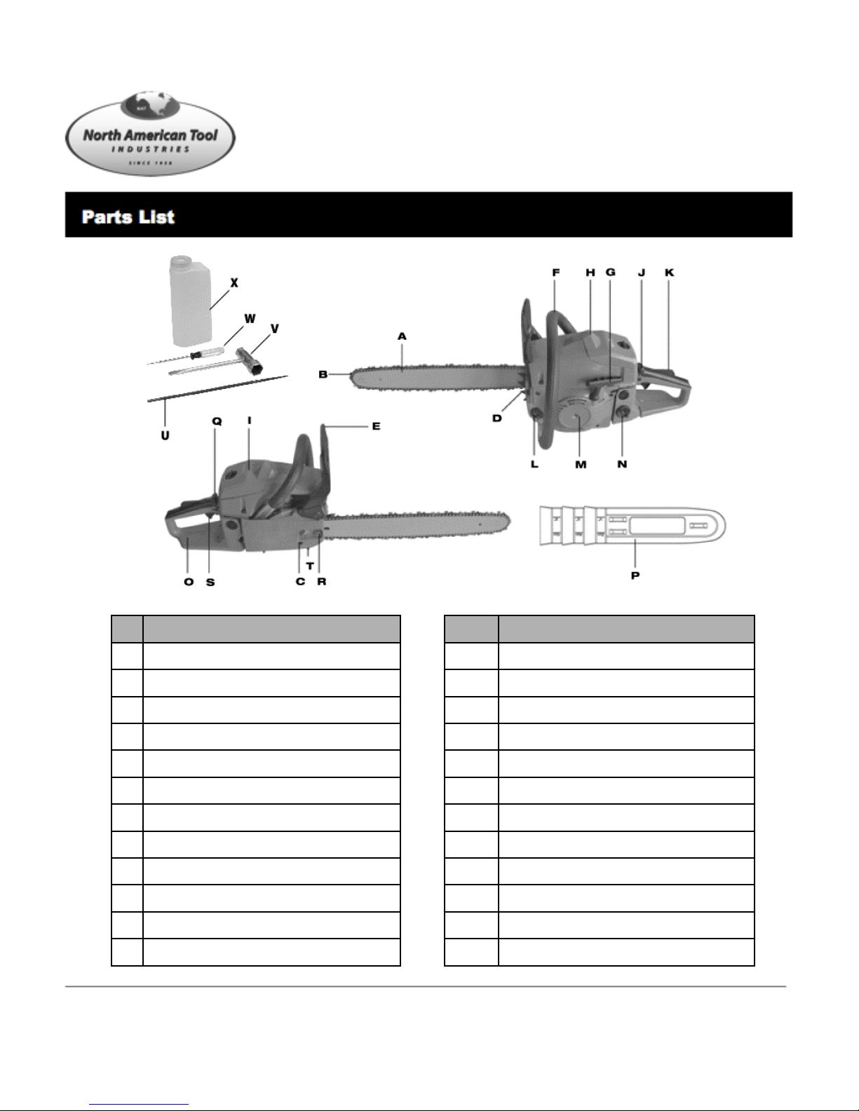
Safety LockK
Oil Tank CapL
Stop SwitchJ
#Part Description
AChain Bar qty 2 (size varies by model)
BSaw Chain qty 2 (size varies by model)
CChain Tensioning Screw
DStop Claw
EChain Brake Lever/Front Hand Guard
FFront Handle
GStarter Handle
HSpark Plug (under air filter cover)
IAir Filter Cover
Screw DriverW
Chain FileU
Plug WrenchV
Chain CatchT
#Part Description
MFan Housing
NFuel Tank Cap
ORear Handle/Bootstrap
PBar Cover
QChoke/Carburetor Setting
RBar Fastening Nut
SThrottle Lever
XMixing Bottle
11
8808902 06/13
12
For customer service, call 1-800-348-5004 or
e-mail feedback@natitools.com
Parts List

8808902 06/13
13
For Customer Service, please call 1-800-348-5004 or
email feedback@natitools.com
Parts List

14
feedback@natitools.com
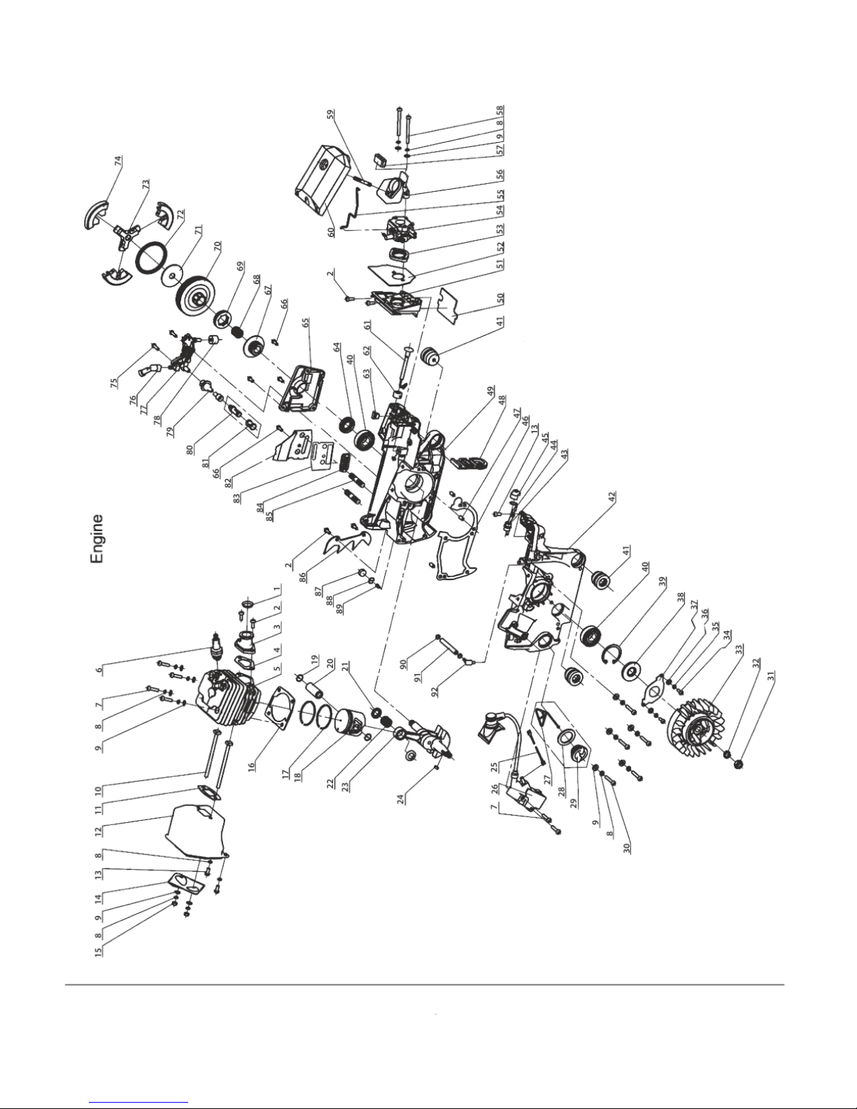
Parts List
Part
Reference#
Parts Description
NATI
SKU#
Qty
Part
Reference#
Parts Description
NATI
SKU#
Qty
1 Retainer Ring
38544 144 Ground Strip 38904 1
2 Screw M5X12
39348 645 Flameout Switch Retainer 38905 1
3 Air Intake Tube
38545 146 Crankshaft Case Gasket 38906 1
4 Air Intake Tube Gasket
38546 147 Pin 38907 3
5 Cylinder
38547 148 Dust Plate 38908 1
6 Spark Plug
38548 149 Right Crankshaft Case 38909 1
7 Screw M5X20
38549 650 Backing Board 38910 1
8 Spring Washer 5
38550 13 51 Air Intake Tube Support 38911 1
9 Washer 5
38551 15 52 Air Intake Tube Support Gasket 38912 1
10 Silencer Bolt
38552 253 Air Intake Flange 38913 1
11 Silencer Gasket
38553 154 Carburetor 38914 1
12 Silencer
38554 155 Accelerator Rod 38915 1
13 Screw M5x10
40946 456 Air Intake 38919 1
14 Silencer Cap
38555 157 Air Intake Cushion 38925 1
15 Nut M5
38556 358 Screw M5-52mm 38929 1
16 Cylinder Gasket
38557 159 Screw 38955 1
17 Piston Ring
38558 260 Air Filter 38956 1
18 Piston
38559 161 Choke Knob 38959 1
19 Piston Pin Circlip
38560 262 Choke Knob Retainer 38969 1
20 Piston Pin
38561 263 Anti-Shock Block 38970 1
21 Needle Bearing Ring
38562 264 Oil Seal 38974 1
22 Needle Bearing
38563 165 Oil Pump Cover Plate 38975 1
23 Crankshaft Components
38669 166 Screw 38976 4
24 Semicircular Key
38748 167 Worm Gear 38994 1
25 Flameout Wire
38812 168 Needle Bearing 39001 1
26 Igniter
38881 169 Sprocket Wheel 39068 1
27 Oil Cap Retainer
38885 170 Clutch Shell w/ Sprocket 39079 1
28 Oil Cap Packing
38888 171 Clutch Washer 39080 1
29 Oil Cap
38889 172 Clutch Extension Spring 39081 1
30 Screw
38890 573 Retainer 39082 1
31 Nut
38891 174 Shoe Block 39083 3
32 Spring Washer 8
38892 172-73-74 Clutch Assembly 43853 1
33 Flywheel
38893 175 Screw 39084 2
34 Screw
38894 276 Oil Nozzle 39085 1
35 Spring Washer 4
38895 277 Oil Pump 39086 1
36 Washer 4
38896 278 Oil Sponge Ring 39087 1
37 Oil Seal Protector Plate
38897 179 Oil Tube 39094 1
38 Oil Seal 15x35x4.5
38898 180 Oil Filter Body 39095 1
39 Snap Ring 35
38899 181 Oil Filter Screen 39096 1
40 Bearing 6202 Grade D
38900 282 Protecting Shield 39151 1
41 Anti-Vibration Cushion D
38901 383 Protecting Shield Cover 39215 1
42 Left Crankshaft Case
38902 184 Chain Guide 39237 1
43 Flameout Switch
38903 185 Screw (Bar Stud M8X28-8.8) 39238 2

15
feedback@natitools.com
Parts List
Part
Reference#
Parts Description
NATI
SKU#
Qty
Part
Reference#
Parts Description
NATI
SKU#
Qty
86 Spiked Bumper 39244 1128 Screw 40900 1
87 Sponge Block 39245 1129 Trigger Controller 44426 1
88 Aeration Nozzle Circlip 39246 1130 Handle Cover 44098 1
89 Aeration Nozzle 39251 1131 Trigger 39369 1
90 Suction Tube Circlip 39252 2132 Trigger Torsion Rod Spring 39369 1
91 Suction Tube 39268 1133 Pin 39369 1
92 Suction Nozzle 39284 1134 Balancer Cover 39369 1
93 Air Filter Lock Nut 39285 1135 Filter 39369 1
94 Lock Nut Washer 39286 1136 Balancer Rubber 39369 1
95 Air Filter Cover 40896 1137 Balancer Body 39369 1
96 Shock Rubber Cushion 39306 1138 Fuel Tube 44029 1
97 Upper Cover Plate 40897 1139 Fuel Tube Base 44030 1
98 Screw 44100 10 140 Fuel Filter Components 44031 1
99 Chain Catcher 39310 1171 Chain Brake Assembly 39368 1
100 Screw 39319 4141 Chain Adjusting Tightener 39341 1
101 Conical Spring Base 39333 1142 Tightening Screw 39342 1
102 Conical Spreader Spring 39334 1143 Tightening Gear 39343 1
103 Idle Adjusting Guide 39335 1144 Brake Spring Cover 39368 1
104 Screw ST4.8X16 39336 4145 Screw 44096 5
105 Front Handle Assembly 39337 1146 Shock Rubber Washer 39368 1
170 Recoil Assembly 39367 1147 Shield Ring 39368 1
106 Kick Spring Base 39367 1148 Washer 39368 1
107 Kick Spring 39367 2149 Brake Torsion Rod Spring 39368 1
108 Starter Cover 39367 1150 Front Guard Tube 39368 1
109 Start Rope 39367 1151 Tightener Cover 39344 1
110 L H Sheathing 39367 1152 Dust Shield 39368 1
111 Coil Spring 39367 1153 Brake Belt 39368 1
112 Starting Handle 39367 1154 Chain Guide 39368 1
113 Coil Spring Shell 39367 1155 Nut 40947 2
114 Starter Wheel 39367 1156 Right Cover 39368 1
115 Big Washer 39367 2157 Shock Rubber Cushion 39368 1
116 Cooling-Air Mask 40899 1158 Cam plate 39368 1
172 Main Frame/Gas Tank Assembly 39369 1159 Shield Ring 39368 1
117 Dust Cover 44092 5160 Front Guard Pin 39368 1
118 Screw M5X16 39319 2161 Shield Ring 39368 1
119 Double-Ended Pin 39369 1162 Front Guard 39368 1
120 Anti-Vibration Cushion C 44097 2163 Positioning Pin 39368 1
121 Fuel Cap 39338 1164 Secondary Brake Spring 39368 1
122 Fuel Cap Washer 39339 1165 Brake Spring 39368 1
123 Fuel Cap Retainer 39340 1166 Brake Control Rod 39368 1
124 Button 44093 1167 Pin 40902 2
125 Button Spring 44094 1168 Secondary Pull-Rod 39368 1
126 Button Shaft 44095 1169 Main Pull-Rod 39368 1
127 Base 39369 1

16
feedback@natitools.com
I. EMISSION CONTROL WARRANTY STATEMENT
YOUR WARRANTY RIGHTS AND OBLIGATIONS
The United States Environmental Protection Agency (EPA), together with North American Tool Industries are
pleased to explain the Emission Control System Warranty on your new small off-road engine. New small off-road
engines must be designed, built, and equipped to meet stringent anti-smog standards for the state of the federal
government. NATI will warrant the emission control system on your engine for the periods of time listed below
provided there has been no abuse, neglect, unapproved modification, or improper maintenance to your engine.
Your emission control system may include parts such as the carburetor, ignition, intake, and exhaust systems. NATI
will repair your engine at no cost to you for diagnosis, replacement parts, and labor, should a warrantable
condition occur.
MANUFACTURER’S EMISSION CONTROL SYSTEM WARRANTY COVERAGE:
Emission control systems on 2012 and later model year engines are warranted for two years as hereinafter noted. If,
during such warranty period, any emission-related component or system on your engine is found to be defective in
materials or workmanship, a NATI Authorized Warranty Service Facility will perform repairs or replacement.
PURCHASER’S/OWNER’S WARRANTY RESPONSIBILITIES:
As the small off-road engine purchaser/owner, you are responsible for the completion of all required maintenance
as listed in your factory supplied OWNER’S MANUAL. For warranty purposes, NATI recommends that you retain
all receipts covering maintenance on your engine. However, NATI cannot deny warranty solely because of the lack
of receipts or for your failure to ensure the completion of scheduled maintenance.
As the small off-road engine purchaser/owner, you should, however, be aware that NATI may deny any and/or all
warranty coverage, or responsibility if your engine, or a part/component thereof, has failed due to abuse, neglect,
improper maintenance, unapproved modifications, or the use of counterfeit and/or “gray market
”
parts not made,
supplied, or approved by NATI.
You are responsible for presenting your engine to a NATI Authorized Warranty Service Facility as soon as a
problem occurs. The warranty repairs should be completed in a reasonable amount of time, not to exceed 30 days.
Warranty service can be arranged by contacting either your selling dealer or a NATI Authorized Warranty Service
Facility. To locate the NATI Authorized Service Facility nearest you, call our toll-free number:
1-800-348-5004
IMPORTANT NOTE: This warranty statement explains your rights and obligations under the Emission Control
System Warranty (ECS Warranty), which is provided to you by NATI pursuant to California and federal law. The
ECS Warranty applies only to the emission control system of your new engine. If there is any conflict in terms
between the ECS Warranty and the NATI Warranty, the ECS Warranty shall apply except in circumstances where
the NATI Warranty may provide a longer warranty period. Both the ECS Warranty and the NATI Warranty describe
important rights and obligations with respect to your new engine.

17
feedback@natitools.com
Only a NATI Authorized Warranty Service Facility can perform warranty service. When requesting warranty
service, evidence must be presented showing the date of the sale to the original purchaser/owner. The
purchaser/owner shall be responsible for any expenses or other charges incurred for service calls and/or
transportation of the product to/from the inspection or repair facilities. The purchaser/owner shall also be
responsible for any and/or all damages or losses incurred while the engine is being transported/shipped for
inspection or warranty repairs.
IF YOU HAVE ANY QUESTIONS REGARDING YOUR WARRANTY RIGHTS AND
RESPONSIBILITIES, YOU SHOULD CONTACT NATI AT THE FOLLOWING ADDRESS:
84 COMMERCIAL RD. HUNTINGTON, IN 46750, USA
feedback@natitools.com
II. EMISSION CONTROL SYSTEM WARRANTY
Emission Control System Warranty (ECS Warranty) for 2012 and later model engines:
(a) Applicability: This warranty shall apply to 2012 and later model year engines. The ECS Warranty
Period shall begin on the date the new engine or equipment is purchased by/delivered to its original,
end-use purchaser/owner and shall continue for 24 consecutive months thereafter.
(b) General Emissions Warranty Coverage: NATI warrants to the original, end-use purchaser/owner of the
new engine or equipment and to each subsequent purchaser/owner that each of its engines is
…
a. Designed, built, and equipped so as to conform with all applicable regulations adopted by the
EPA pursuant to their respective authority, and
b. Free from defects in materials and workmanship which, at any time during the ECS Warranty
Period, may cause a warranted emissions-related part to fail to be identical in all material
respects to the part as described in the engine manufacturer’s application for certification.
The ECS Warranty only pertains to emission-related parts on your engine, as follows:
1. Any warranted, emissions-related parts that are not scheduled for replacement as required maintenance
in the Owner’s Manual shall be warranted for the ECS Warranty Period. If any such part fails during
the ECS Warranty Period, it shall be repaired or replaced by NATI according to subsection 4 below.
Any such part repaired or replaced under the ECS Warranty shall be warranted for the remainder of
the ECS Warranty Period.
2. Any warranted, emissions-related part that is scheduled only for regular inspection as specified in the
Owner’s Manual should be warranted for the ECS Warranty Period. A statement in such written
instructions to the effect of “repair or replace as necessary”shall not reduce the ECS Warranty Period.
Any such part repaired or replaced under the ECS Warranty shall be warranted for the remainder of
the ECS Warranty Period.

18
feedback@natitools.com
3. Any warranted, emissions-related part that is scheduled for replacement as required maintenance
in the Owner’s Manual shall be warranted for the period of time prior to the first scheduled
replacement point for that part. If the part fails prior to the first scheduled replacement, the part
shall be repaired or replaced by NATI according to subsection 4 below. Any such emissions-related
part repaired or replaced under the ECS Warranty shall be warranted for the remainder of the ECS
Warranty Period prior to the first scheduled replacement point for such emissions-related part.
4. Repair or replacement of any warranted, emissions-related part under this ECS Warranty shall be
performed at no charge to the owner at a NATI Authorized Warranty Service Facility.
5. When the engine is inspected by a NATI Authorized Warranty Service Facility, the owner shall not
be held responsible for diagnostic costs if the repair is deemed warrantable.
6. NATI shall be liable for damages to other original engine components or approved modifications
proximately caused by a failure under warranty of any emission-related part covered by the ECS
warranty.
7. Throughout the ECS Warranty Period, NATI shall maintain a supply of warranted emission-related
parts sufficient to meet the expected demand for such emissions-related parts.
8. Any NATI authorized and approved emissions-related replacement parts may be used in the
performance of any ECS Warranty maintenance or repairs and will be provided without charge to
the purchaser/owner. Such use shall not reduce NATI’s ECS Warranty obligations.
9. Unapproved, add-on, modified, counterfeit, and/or “gray market
”
parts may not be used to modify
or repair a NATI engine. Such use voids this ECS Warranty and shall be sufficient grounds for
disallowing an ECS Warranty claim. NATI shall not be held liable hereunder for failures of any
warranted parts of a NATI engine caused by the use of such an unapproved, add-on, modified,
counterfeit, and/or “gray market
”
part.

19
feedback@natitools.com
EMISSIONS-RELATED PARTS INCLUDE THE FOLLOWING:
For engine families CZHWS.0454SN
1. Fuel Metering System:
a. Gasoline carburetor assembly and its internal components (if so equipped).
b. Fuel Filter (if so equipped).
c. Carburetor Gaskets
d. Fuel Pump (if so equipped).
e. Fuel Hose
f. Clamps
2. Air Induction System including:
a. Intake Pipe/Manifold
b. Air Cleaner
3. Ignition System including:
a. Spark Plug
b. Ignition Module/Coil
4. Catalytic Muffler Assembly (if so equipped)
a. Muffler Gasket
b. Exhaust Manifold
5. Crankcase Breather Assembly including:
a. Breather Connection Tube
6. Fuel tank evaporative emissions control system include:
a. Fuel Tank
b. Fuel Cap
c. Fuel Hose
d. Clamps
7. Miscellaneous items used in above systems including:
a. Switches
b. Hoses, Belts, Connectors, and Assemblies
This manual suits for next models
3
Table of contents
Other North American Tool Chainsaw manuals


