North Invent SL150-01.MON.03 User manual
Specifications subject to changes without prior notice.The contents of
this page are property of North Invent Norway AS. All rights herein are
reserved to North lnvent Norway AS. This document cannot be
reproduced without the written permission of the company.
SeaLine MK3 Monitors
NORTH INVENT
Sørhauggata 128, NO-5527 Haugesund, Norway
hone: + 47 48 84 02 00
post@northinvent.com www.northinvent.com
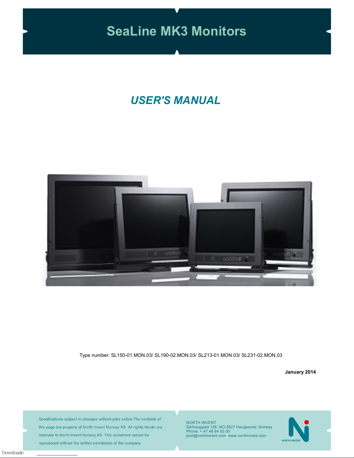
Type number: SL150-01.MON.03/ SL190-02.MON.03/ SL213-01.MON.03/ SL231-02.MON.03
January 2014
USER'S MANUAL

SeaLine MK3 Monitors
Specifications subject to changes without prior notice.The contents of
this page are property of North Invent Norway AS. All rights herein are
reserved to North lnvent Norway AS. This document cannot be
reproduced without the written permission of the company.
NORTH INVENT
Sørhauggata 128, NO-5527 Haugesund, Norway
hone: + 47 48 84 02 00
post@northinvent.com www.northinvent.com
2
TableofContents
1. Foreword ...................................................................................................................................................................... 3
1.0 Terms and abbreviations..................................................................................................................3
1.1 Monitor description ........................................................................................................................... 3
1.2 Main schematic overview .................................................................................................................. 6
1.3 Packaging and delivery ...................................................................................................................... 6
1. Mechanical Dimensions .................................................................................................................... 7
1.5 Mechanical installation .................................................................................................................... 13
1.6 Electrical installation ....................................................................................................................... 1
2. Operating Instructions ............................................................................................................................................ 16
2.1 Controls and indicators .................................................................................................................... 16
2.2 Start-up .......................................................................................................................................... 16
2.3 Source Input Messages .................................................................................................................... 17
2. On Screen Display (OSD) ................................................................................................................ 17
2. .1 OSD division into folders, menus, sub-menus ................................................................................. 18
2. .2 OSD items .......................................................................................................................................... 19
2. .3 OSD items stages ............................................................................................................................... 19
2. . Entering and adjusting the OSD ......................................................................................................... 19
2. .5 OSD content ....................................................................................................................................... 20
Tools………………………………………………………………………………………………………..…19
Functions ......................................................................................................................................................... 23
Picture .............................................................................................................................................................. 25
RGB mode wizard ........................................................................................................................................... 26
Info .................................................................................................................................................................. 27
2.5 Mode Table .................................................................................................................................... 28
2.6 Remote control ............................................................................................................................... 29
3. Technical specifications ......................................................................................................................................... 3
3.1 Summary ........................................................................................................................................ 3
3.2 Firmware Revision table .................................................................................................................. 35
3.3 Troubleshooting .............................................................................................................................. 35
3. Cleaning ......................................................................................................................................... 36
3.5 Update ........................................................................................................................................... 36
. Maintenance and service ........................................................................................................................................ 36

SeaLine MK3 Monitors
Specifications subject to changes without prior notice.The contents of
this page are property of North Invent Norway AS. All rights herein are
reserved to North lnvent Norway AS. This document cannot be
reproduced without the written permission of the company.
NORTH INVENT
Sørhauggata 128, NO-5527 Haugesund, Norway
hone: + 47 48 84 02 00
post@northinvent.com www.northinvent.com
3
1. Foreword
Thanks for purchasing a North Invent Sea Line Monitor. Our series of rugged TFT LCD Display Monitors are
conceived and built with the greatest care and state of the art electronic and software features. North Invent
focuses its full expertise in offering dedicated display solutions, matching with your highest requirements and
use.
Before starting operating the Monitor, we would like to suggest that you carefully read through the present
document, as our aim with this User’s Manuel is to give you the best experience in using our Monitors.
May you have any suggestions for improvements, or any feedbacks about this manual, the Monitor and/or its
features, feel free to contact us. We will be pleased to oblige.
This User’s Manual is for use only with our Sea Line MK3 Monitors. To assess which series of Monitor you are
in possession of, please check the Serial Number plate at the back of the screen. The mention shall bear
MON.03 (see below). May you have a different series of Monitor, please contact us, so to have the proper
manual sent to your attention.
Terms and abbreviations
DVI Digital Visual Interface
DVI-A - Analog
DVI-I -Integrated
HMI Human- Machine Interface
LCD Liquid Crystal Display
LED Light-Emitting Diode
OSD On-Screen Display
RGB Red-Green-Blue
TFT Thin Film Transistor
VGA Video Graphics Array
1.1 Monitor description
The Sea Line monitors are a series of rugged TFT LCD Display Monitors available in 15’’, 19’’, 21.3’’ and 23.1’’
display sizes. All of our Monitors can be flush mounted or equipped with stand, turntable and/or sunshade.
xEach Sea Line MK3 Monitor is designated as below:

SeaLine MK3 Monitors
Specifications subject to changes without prior notice.The contents of
this page are property of North Invent Norway AS. All rights herein are
reserved to North lnvent Norway AS. This document cannot be
reproduced without the written permission of the company.
NORTH INVENT
Sørhauggata 128, NO-5527 Haugesund, Norway
hone: + 47 48 84 02 00
post@northinvent.com www.northinvent.com
4
Where “SL” stands for Sea Line, “150/190/213/231” for the display’s Size, “01/02” for the hardware Revision,
“MON“ for Monitor, “03” for Version MK3 and “xxxx” for identification of minor variants (bezel colors, flash logo,
OEM labels etc.).
xEach Monitor is constituted by the following set of components:
- Front glass with the User Interface anel
- Display Frame and all necessary electronic components
- Rear cover and Terminal plate
- 1 x ower AC Cable / 1 x DC plug / 1 x VGA Cable
- 4 x M6 x 25, Stainless Steel screws for front mounting / 4 x Cover for M6 screws
(optional)
- Stand
- Turntable
- Sunshade
xEach Monitor presents the following materials and features:
- The Front, Display Frame, Cover, Stand, Turntable and Sunshade are made of Marine Grade
Aluminium allowing to reduce weight while eliminating corrosion problems.
- The electronic set of components includes a specifically designed ower Supply, a high quality Display
Controller, a Backlight Inverter, with sealed transformers, and a custom-made Interface Board.
- All our Monitors use identical ower Supply and User anel. The ower Supply can be supplied with
115/230 VAC and/or 24 VDC, and even be used as a part of an U S.
- All our Monitors can be flush mounted (front or back tightened with stainless screws) or used as free
standing units with use of a Stand and/or a Turntable.
- Furthermore, when flush mounted, all our Monitors can be water- and dust- tight sealed, with the use of
optional Sealing Kits, to be mounted at the back of the display frame into the dedicated sealing groove.
These specific (per size of Monitor) Sealing Kits being recommended to further protect all electronics,
against harsh environment.
- All our Monitors come with VGA, DVI, S-Video and Composite video inputs, and a RS232 input for
remote control purposes.
- ixel pitch on all displays are 0,294 mm both in x and y direction. This pixel pitch equals 1 m viewing
distance with a viewing angle of 1 minute of arc as required in IEC 62.388 section 6.13.2.b.
Nominal viewing distance in a normal environment is 1,0 m.

SeaLine MK3 Monitors
Specifications subject to changes without prior notice.The contents of
this page are property of North Invent Norway AS. All rights herein are
reserved to North lnvent Norway AS. This document cannot be
reproduced without the written permission of the company.
NORTH INVENT
Sørhauggata 128, NO-5527 Haugesund, Norway
hone: + 47 48 84 02 00
post@northinvent.com www.northinvent.com
5
xEach Monitor complies with the following international Standards and Requirements:
- All our Monitors has been tested by the Danish testing body “DELTA” (Danish
Electronics, Light & Acoustics, DK-2970 Hørsholm) and found to comply with the requirements of the
International Association of Classification Societies (IACS) as well as the selected requirements of IEC
60945, IEC 60533, IEC 60529 and MIL-STD-810F.
- All our Monitors are approved in compliance with the international standard IEC 60945 : 2002 (Clause
4.4 Equipment category b, protected from the weather (formerly class B)), Maritime navigation and
radiocommunication equipment and systems - General requirements - Methods of testing and required
test results.
- The compass safe distance indication is placed on the rear label (see figure 1.) and is valid for the
Monitor only. It excludes accessories like sunshade, turntable and stand.
SeaLine MK3 Monitors
Specifications subject to changes without prior notice.The contents of
this page are property of North Invent Norway AS. All rights herein are
reserved to North lnvent Norway AS. This document cannot be
reproduced without the written permission of the company.
NORTH INVENT
Sørhauggata 128, NO-5527 Haugesund, Norway
hone: + 47 48 84 02 00
post@northinvent.com www.northinvent.com
6
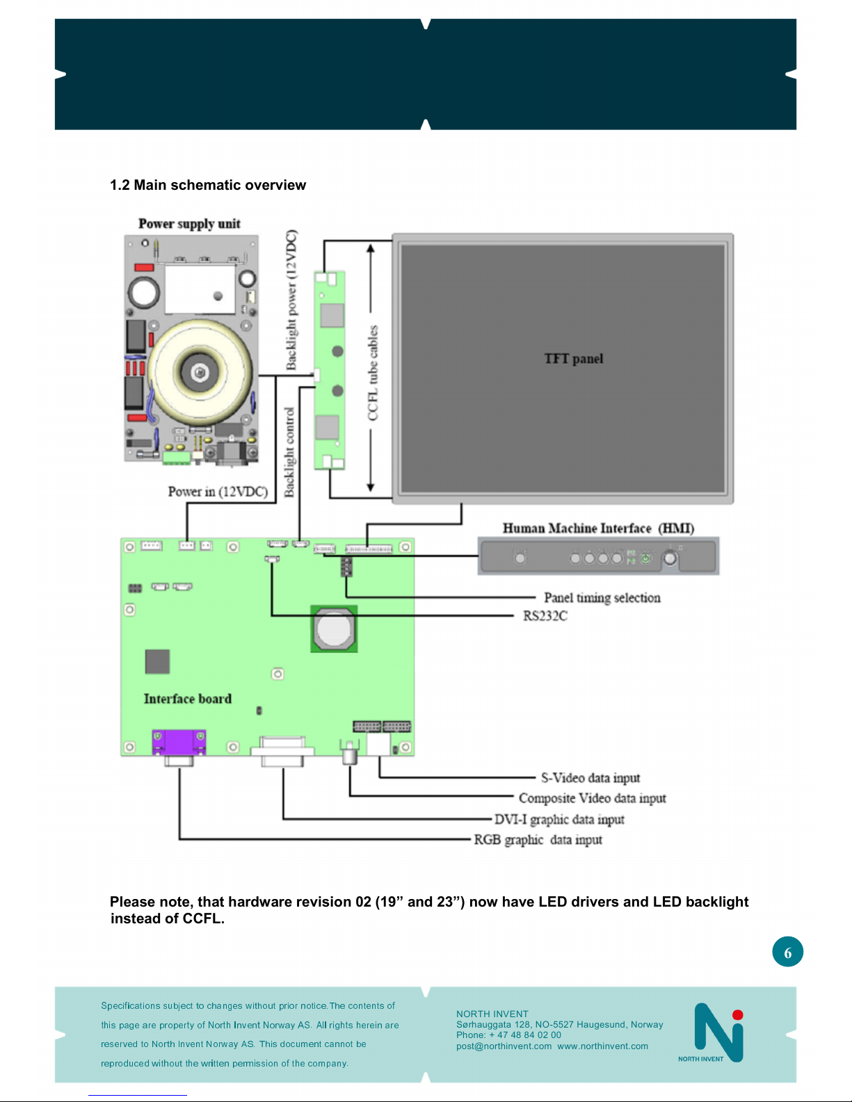
1.2 Main schematic overview
Please note, that hardware revision 02 (19” and 23”) now have L D drivers and L D backlight
instead of CCFL.

SeaLine MK3 Monitors
Specifications subject to changes without prior notice.The contents of
this page are property of North Invent Norway AS. All rights herein are
reserved to North lnvent Norway AS. This document cannot be
reproduced without the written permission of the company.
NORTH INVENT
Sørhauggata 128, NO-5527 Haugesund, Norway
hone: + 47 48 84 02 00
post@northinvent.com www.northinvent.com
7
1.3 Packaging and delivery
lease check the delivered goods immediately on receipt with respect to damages caused by transportation and
inform the delivering freight carrier immediately, on site, about any visible transport damages. Additionally,
inform us immediately in writing, at the latest within 5 work days, about any visible transport damages. At
reception, the delivery includes the following items:
- Sea Line MK3 Monitor
- Sea Line MK3 User’s Manual
- VGA cable
- AC power cable
- DC power plug
- Front mounting screws and screw covers
- DVI cable (optional)
- Stand (optional)
- Stand mounting screws and screw covers (optional)
- Turntable (optional)
- Turntable mounting screws and screw covers (optional)
- Sunshade (optional)
- Sunshade mounting screws and screw covers (optional)
- Sealing Kit (optional)

SeaLine MK3 Monitors
Specifications subject to changes without prior notice.The contents of
this page are property of North Invent Norway AS. All rights herein are
reserved to North lnvent Norway AS. This document cannot be
reproduced without the written permission of the company.
NORTH INVENT
Sørhauggata 128, NO-5527 Haugesund, Norway
hone: + 47 48 84 02 00
post@northinvent.com www.northinvent.com
8
1.4 Mechanical Dimensions
Panel cut out dimensions
Measurements (mm)
Panel type
A B C D F
SL150-01.MON.03 368 313 377.5 66.5 180 66.5
SL190-02.MON.03 438 385 447.5 82.5 220 82.5
SL213-01.MON.03 501.8 422 511.3 93.75 234.5 93.75
SL231-02.MON.03 564 493.8 573.5 111.7 270.4 111.7
SeaLine MK3 Monitors
Specifications subject to changes without prior notice.The contents of
this page are property of North Invent Norway AS. All rights herein are
reserved to North lnvent Norway AS. This document cannot be
reproduced without the written permission of the company.
NORTH INVENT
Sørhauggata 128, NO-5527 Haugesund, Norway
hone: + 47 48 84 02 00
post@northinvent.com www.northinvent.com
9
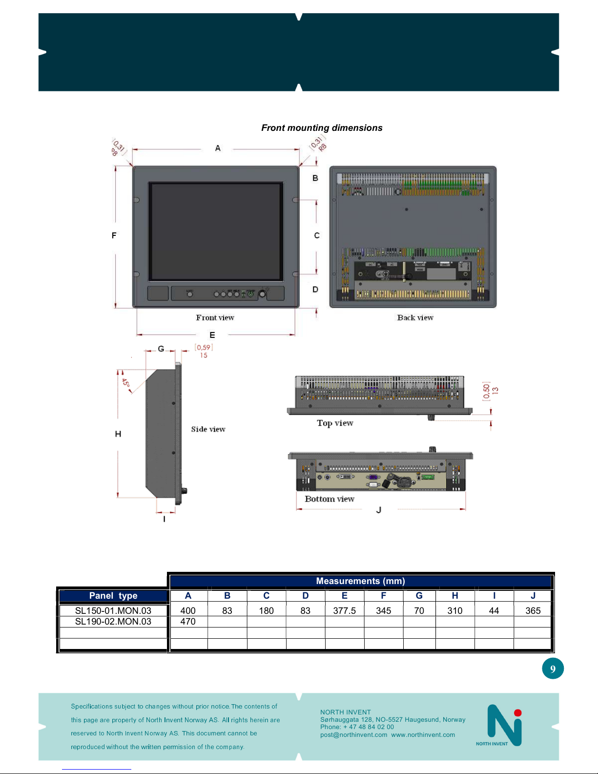
Front mounting dimensions
Measurements (mm)
Panel type
A
B
C
D
E
F
G
H
I
SL150-01.MON.03 400 83 180 83 377.5 345 70 310 44 365
SL190-02.MON.03 470 98.5 220 98.5 447.5 417 70 382 44.1 435
SL213-01.MON.03 533.8 109.75 234.5 109.75 511.3 454 75.4 419 49.48 498.8
SL231-02.MON.03 596 127.7 270.4 127.7 573.5 525.8 77.4 490.8 51.48 561
SeaLine MK3 Monitors
Specifications subject to changes without prior notice.The contents of
this page are property of North Invent Norway AS. All rights herein are
reserved to North lnvent Norway AS. This document cannot be
reproduced without the written permission of the company.
NORTH INVENT
Sørhauggata 128, NO-5527 Haugesund, Norway
hone: + 47 48 84 02 00
post@northinvent.com www.northinvent.com
10
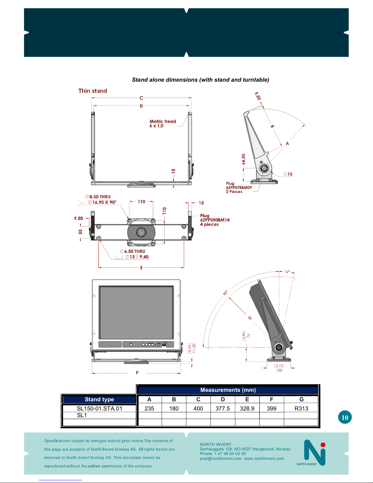
Stand alone dimensions (with stand and turntable)
Measurements (mm)
Stand type
A
B
C
D
E
F
G
SL150-01.STA.01 235 180 400 377.5 328.9 399 R313
SL190-01.STA.01 290 220 470 447.5 399 469.55 R384
SL213-01.STA.01 315.5 234.5 533.8 511.3 462.6 533 R420.21
SeaLine MK3 Monitors
Specifications subject to changes without prior notice.The contents of
this page are property of North Invent Norway AS. All rights herein are
reserved to North lnvent Norway AS. This document cannot be
reproduced without the written permission of the company.
NORTH INVENT
Sørhauggata 128, NO-5527 Haugesund, Norway
hone: + 47 48 84 02 00
post@northinvent.com www.northinvent.com
11
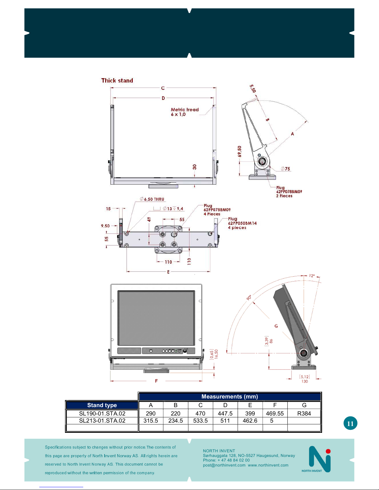
Measurements (mm)
Stand type
A B C D E F G
SL190-01.STA.02 290 220 470 447.5 399 469.55 R384
SL213-01.STA.02 315.5 234.5 533.5 511 462.6 533 R420.21
SL231-01.STA.01 361 270.4 596 573.5 526 596 R483.44

SeaLine MK3 Monitors
Specifications subject to changes without prior notice.The contents of
this page are property of North Invent Norway AS. All rights herein are
reserved to North lnvent Norway AS. This document cannot be
reproduced without the written permission of the company.
NORTH INVENT
Sørhauggata 128, NO-5527 Haugesund, Norway
hone: + 47 48 84 02 00
post@northinvent.com www.northinvent.com
12
Stand alone dimensions (with stand, turntable and sunshade)

SeaLine MK3 Monitors
Specifications subject to changes without prior notice.The contents of
this page are property of North Invent Norway AS. All rights herein are
reserved to North lnvent Norway AS. This document cannot be
reproduced without the written permission of the company.
NORTH INVENT
Sørhauggata 128, NO-5527 Haugesund, Norway
hone: + 47 48 84 02 00
post@northinvent.com www.northinvent.com
13
1.5 Mechanical installation
All our Monitors are delivered with all necessary accessories as specified on the order confirmation.
xFront mounting
- When the Monitor is flush mounted, one must imperatively use the 4 x M6 screws and covers enclosed in the
delivery. The tightening moment must be of 8-10 Nm.
xStand mounting
- The Monitor is fixed to the Stand by using the 4 x M6 screws and covers enclosed in the delivery. The
tightening moment must be of 8-10 Nm.
- The viewing angle of the Monitor can be adjusted from -12° to 90° (vertical) and maintained in position by
using the manual screws on each side of the Stand. ull out the screws and turn them anticlockwise until
they are loose. Move the Monitor to the desired viewing angle and turn the manual screws clockwise this
time, until they are tightened again.
- If the Monitor is exposed to severe vibration or shock, firmly maintain it in position by using 2 x M10 nuts on
each side of the Stand.
- 2 versions of stand are available thin (single layer) or thick (double layer). The reinforced stand will be more
stable for bigger Monitors size, such as the 19”, 21.3” and 23.1” ones.
xTurntable mounting
- When ordered together, the Turntable comes mounted on the Stand on delivery.
- Orientation of the Monitor can be made from 0-360° by simply turning the Monitor with a slight lateral
pressure on the turntable. The forced needed to turn the Monitor can be adjusted using the M10 nuts on the
top of the Turntable. Remove the plastic covers and loose or tighten the screws. Remember to reposition the
plastic covers again.
- If the Monitor is exposed to severe vibration or shock the M10 screws can be tightened at 8-10 Nm.
Remember to loose the screws before adjusting the Turntable again.
- The Monitor is fixed to the Stand by using the 4 x M6 screws and covers enclosed in the delivery. The
tightening moment must be of 8-10 Nm.
xSunshade mounting
- The Sunshade is fixed to the Monitor by using the 4 x M3 screws and covers enclosed in the delivery.
- Remove the 4 screw covers from the Monitor’s frame and position the Sunshade on the Monitor. The
Sunshade screws will fit into the hole and shall be tightened at 2-3 Nm. Remember to position the covers
again.
SeaLine MK3 Monitors
Specifications subject to changes without prior notice.The contents of
this page are property of North Invent Norway AS. All rights herein are
reserved to North lnvent Norway AS. This document cannot be
reproduced without the written permission of the company.
NORTH INVENT
Sørhauggata 128, NO-5527 Haugesund, Norway
hone: + 47 48 84 02 00
post@northinvent.com www.northinvent.com
14
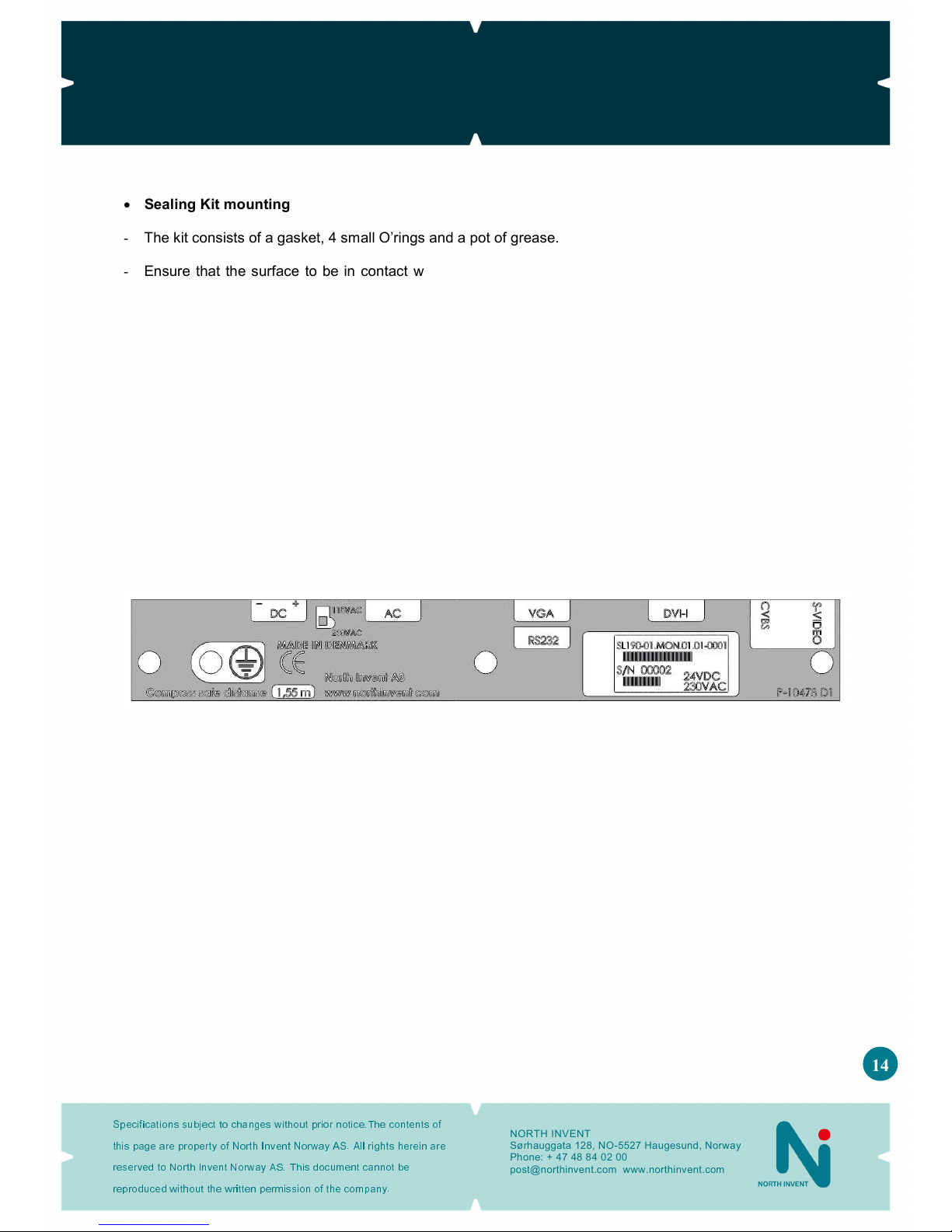
xSealing Kit mounting
- The kit consists of a gasket, 4 small O’rings and a pot of grease.
- Ensure that the surface to be in contact with the back of the frame, and thus the gasket, is plane and has
been cleaned, prior to firmly flush mount the Monitor in place.
- The gasket must be positioned totally into the surrounding groove at the back of the Monitor’s frame. Cover
both the gasket and the front evenly with grease. osition carefully the monitor in the panel cut out, and
adjust the edge of the gasket so that it levels the front.
- osition the 4 small O’rings into their respective screw holes, grease slightly every one of them before
tightening the 4 front screws.
1.6 Electrical installation
- All electrical connections are to be found on the lower back side of the Monitor. All necessary electrical
indications are to be found on the Terminal late at the bottom of the Monitor’s backside.
- May the Monitor be exposed to severe vibration or shocks, all electrical cables can firmly be maintained in
position, using the 2 black plastic cable retainers.
Figure 1. Terminal late for a 19” Sea Line Monitor.
xPower supply
- The Monitor can be supplied with 115/230 VAC and/or 24 VDC. The AC voltage can be selected on a slide
switch placed between the AC and DC input connectors. The lower position (by default) selects 230 VAC
while the upper position selects 115 VAC.
- The Monitor is connected to AC voltage by means of the standard AC power cable included in the delivery.
The AC current to the Monitor must be limited by a 10A fuse or similar.
- The Monitor is connected to DC voltage by means of the DC power plug included in the delivery and wires
suitable for up to 8 A. The Monitor will not be damaged by reversed polarity, may it occur.
xEarth connection
- On the Terminal late an icon, marked with an earth symbol, is presented for placing of the earth connection
screw, allowing safe earth connection. lease use a cable of minimum 1.3 mm2 (16 AWG) with crimp
terminals.
- Remember to fasten the earth connection screw for adequate earth connection.

SeaLine MK3 Monitors
Specifications subject to changes without prior notice.The contents of
this page are property of North Invent Norway AS. All rights herein are
reserved to North lnvent Norway AS. This document cannot be
reproduced without the written permission of the company.
NORTH INVENT
Sørhauggata 128, NO-5527 Haugesund, Norway
hone: + 47 48 84 02 00
post@northinvent.com www.northinvent.com
15
xVGA cable (Analog RGB)
- The VGA cable is included in the delivery.
- Remember to fasten the VGA cable’s fixing screws for adequate connection.
xDVI cable (Digital RGB)
- The DVI cable is not included in a standard delivery but is available as an option.
- The DVI cable is to be connected to the DVI-I terminal.
- Remember to fasten the DVI cable’s fixing screws for adequate connection.
xVideo cables
- Video signals can be obtained by connecting the Monitor to the S-VHS (S-Video) and CVBS (composite
video) terminals. The video cables must be of high quality in order to avoid signal’s interference.
xRS232 cable
- The Monitor is equipped with a standard 9-pin D-SUB female connector for RS232 remote control.
- Further information about this interface and the remote control is to be found in the Remote Control section.
xCom ass safe-distance
- Every component of type approved equipment is tested in order to determine the minimum safe distances at
which it should be installed from both the steering and the standard magnetic compasses, so not to
significantly affect the accuracy of these compasses. The safe compass distances are mentioned on every
Monitor or in the accompanying handbook. A safe distance takes into account both the constant effect on a
magnetic compass, of the presence of magnetic material but also any variable effect due, for instance, to
electrical circuits or the opening/closing of drawers or panels. Thus, provided that a Monitor is not placed in a
position nearer to the centre of the bowl of a magnetic compass than the recommended safe distance, the
Monitor may be installed or removed without any need for adjustment of that compass.
- SL150-01.MON.03 1.00m
- SL190-02.MON.03 1.55m
- SL213-01.MON.03 1.60m
- SL231-02.MON.03 2.10m
- The safe distance is also indicated on the terminal plate of every Monitor as shown on Figure 1.
Figure 1. Terminal late for a 19” Sea Line Monitor.

SeaLine MK3 Monitors
Specifications subject to changes without prior notice.The contents of
this page are property of North Invent Norway AS. All rights herein are
reserved to North lnvent Norway AS. This document cannot be
reproduced without the written permission of the company.
NORTH INVENT
Sørhauggata 128, NO-5527 Haugesund, Norway
hone: + 47 48 84 02 00
post@northinvent.com www.northinvent.com
16
2. Operating Instructions
The following instructions assume that the Monitor has been correctly installed and that the commissioning work
has been finalised.
2.1 Controls and indicators
- Controls and Indicators are placed on the User anel in the lower right side of the Monitor.
- Normal functioning of the Control knobs and Indicators are explained in the following table:
Control / Indicator Function
OWER ress once to switch the Monitor ON.
ress for 5 sec to switch the Monitor OFF.
AC Indicates that the Monitor is supplied with 115 or 230 VAC.
DC Indicates that the Monitor is supplied with 24 VDC
LOCK
ress once to activate the OSD in unlocked state.
ress LOCK and MENU for 5 sec to unlock and activate the OSD in
locked state.
MENU
ress once to activate the OSD in unlocked state.
ress once to deactivate the OSD again.
ress once to change from sub to main menu.
SET
ress to indicate/change the video input source (OSD not active).
ress once to go to the selected sub menu (OSD active).
ress once to set or unset the selected sub menu (OSD active).
+
ress and hold to increase the indicator brightness (OSD not active).
ress once to select the next menu (OSD active).
ress or hold to increase values (OSD active).
−
ress or hold to decrease the indicator brightness (OSD not active).
ress once to select the previous menu (OSD is active).
ress or hold to decrease values (OSD active).
DIMMING KNOB Turn clockwise to increase the screen’s backlight (brightness).
Turn anticlockwise to decrease the screen’s backlight (dimming).
Figure 2. Front anel with controls and indicators.
2.2 Start-up
- Ensure that power and a valid video signal are supplied to the Monitor. Standard video signals are listed in
the Mode Table section below.

SeaLine MK3 Monitors
Specifications subject to changes without prior notice.The contents of
this page are property of North Invent Norway AS. All rights herein are
reserved to North lnvent Norway AS. This document cannot be
reproduced without the written permission of the company.
NORTH INVENT
Sørhauggata 128, NO-5527 Haugesund, Norway
hone: + 47 48 84 02 00
post@northinvent.com www.northinvent.com
17
- ress the ower control once – the ower, LOCK and relevant AC/DC indicators will light up. The control
and indicator backlight can be adjusted using the +/− controls. When Locked (e.g. ECDIS mode) the
indicator and the control panel backlight will follow dimming of the display backlight. In ECDIS mode the
backlight, control and indicator are preset to Day, Dusk and Night (controlled via RS232).
- The Monitor will search for a video signal on the last selected input source. If the Monitor states “No Input
Signal – Going to Sleep”, the correct source can be selected using the OSD (see below). The default source
is the standard VGA input.
- The screen brightness can now be adjusted using the dimming Knob on the Front anel and the picture
positioning and size can be adjusted using the OSD (see below).
2.3 Source Input Messages
- After start-up of the Monitor a short message will appear in the same space provided for the OSD (see
below). The different messages are explained in the following table.
Message Explanation
Analog RGB searching The Monitor is searching for a valid video signal connected to the VGA input
Digital RGB searching The Monitor is searching for a valid video signal connected to the DVI input
S-Video searching The Monitor is searching for a valid video signal connected to the S-VHS input
Composite Video searching The Monitor is searching for a valid video signal connected to the CVBS input
No Input Signal - Going to Sleep The Monitor did not find any video signal on the selected input source
Out of range The video signal on the selected input source is out of range
BW Limit exceeded Input signal exceeds bandwidth (when I /SBS) or instead of “Out of range”
- When the Monitor detects a valid video signal it will shortly indicate the source input, resolution and
frequency of the input signal, as well as the video mode number.
- The input source can be selected using the OSD (see below).
- If the video signal is out of range either the resolution or frequency is too high for the Monitor. The message
is also given if the current video mode is not included in the Mode Table (see below).
- Additional video modes can be added upon request.
2.4 On Screen Display (OSD)
- Most functions of the Monitor can be controlled using the OSD.
- The OSD is activated by pressing the LOCK or MENU control. The monitor is equipped with a lock function
which prevents accidental use of the OSD. The lock function does not affect the indicator brightness and
backlight controls. The status of the lock function is controlled by the OSD and remote control. The monitor is
always locked when a valid RS232 signal is available. If the Monitor is in locked state the OSD can only be
activated by pressing the LOCK and MENU buttons at the same time for 5 sec.

SeaLine MK3 Monitors
Specifications subject to changes without prior notice.The contents of
this page are property of North Invent Norway AS. All rights herein are
reserved to North lnvent Norway AS. This document cannot be
reproduced without the written permission of the company.
NORTH INVENT
Sørhauggata 128, NO-5527 Haugesund, Norway
hone: + 47 48 84 02 00
post@northinvent.com www.northinvent.com
18
- The screen backlight (brightness) can be adjusted using the KNOB on the front panel but it can also be
adjusted using the OSD and remote control. There is a little mark above the KNOB control which indicates its
calibrated setting. This setting must be used when the backlight is being controlled by the OSD or remote
control. If the KNOB control is not positioned correct the OSD or remote control will not be able to adjust the
brightness correct. If the backlight is only to be controlled by the KNOB the OSD backlight setting must be
fixed at 50%.
- The next and previous menu can be selected using + / − controls.
- The sub menus are selected using the SET control and values can be increased/decreased using + / −
controls. The SET control is also used to set the value and leave the sub menu.
- ress the MENU control once to return to the main menu and once again to leave the OSD.
- The OSD will be deactivated the selected period after the last control has been pressed (OSD timeout).
2.4.1 OSD division into folders, menus, sub-menus
Figure 3. On Screen Display

SeaLine MK3 Monitors
Specifications subject to changes without prior notice.The contents of
this page are property of North Invent Norway AS. All rights herein are
reserved to North lnvent Norway AS. This document cannot be
reproduced without the written permission of the company.
NORTH INVENT
Sørhauggata 128, NO-5527 Haugesund, Norway
hone: + 47 48 84 02 00
post@northinvent.com www.northinvent.com
19
2.4.2 OSD items
- Depending on the menu chosen, different types of items can appear:
Push button
- activates a sub-menu or a function
List
- a value can be chosen from a list
Slide bar
– slide the bar to choose the desired level from 0-100%
ON/OFF
- turns the settings On or Off
Information
- contains pure text or value information
2.4.3 OSD items sta es
- Folder items, menu items, and sub-menu items exist in three different stages:
Inactive
- when the OSD is opened all folders, menus, and sub-
menus are by
default inactive, and the only item that is selected is the ‘Tools’ folder.
Selected
-
when the user navigates through the OSD, part of the selected item is
blue. It can not be adjusted before activated ( ress ENTER).
Activated -
the item is activated and can be adjusted. To activate an item, push
the ENTER button on the HMI (Human Machine Interface).
2.4.4 Enterin and adjustin the OSD
- The OSD menu can always be opened and closed by pressing the MENU button on the HMI (except when
locked, see 2.4 on page 16). Once the menu has been opened it can be navigated up/down and right/left
using ‘+’ and ‘-’ buttons. To be able to adjust the settings, an item has to be active, which is effectuated by
pressing the ENTER button.
- To make adjustments in the OSD, follow these steps:
1. ress the MENU button on the HMI to activate the OSD.
2. Navigate up and down in the different folders with ‘+’ and ‘-’ buttons.
3. When the desired folder is partly highlighted, press the SET button to activate the menu.
4. Navigate with the + and - buttons until the desired control has been reached (and partly highlighted).
To gain adjustment control, press SET. The control will be highlighted and can now be adjusted.
5. ress + to increase the value or - to decrease the value.
6. When the right level has been reached, press SET once again to activate the adjustment and
automatically jump one level back.
7. To exit the OSD, press MENU.
SeaLine MK3 Monitors
Specifications subject to changes without prior notice.The contents of
this page are property of North Invent Norway AS. All rights herein are
reserved to North lnvent Norway AS. This document cannot be
reproduced without the written permission of the company.
NORTH INVENT
Sørhauggata 128, NO-5527 Haugesund, Norway
hone: + 47 48 84 02 00
post@northinvent.com www.northinvent.com
20
- The following exemplifies how to adjust the settings for Saturation:
1. ress MENU to activate the OSD
2. Use + or - to navigate up or down until you have selected the Functions folder (the icon will be
coloured).
3. ress SET to activate the folder (the folder will turn blue, and automatically the first menu item in the
sub-menu will be selected - in this case the ‘Source enabling’ button)
4. Use ‘+’ to navigate to DVI-A (or other Source input) and press ‘SET’ to activate
5. Navigate down with the + button until you have selected the menu item ‘Saturation’
6. ress SET to activate the menu item.
7. Use + or - to set the desired value for the saturation
8. ress SET to validate the change - the OSD automatically jumps one level back
2.4.5 OSD content
- The OSD is designed with 5 different folders: Tools, Functions, icture, RGB mode wizard, and Info, each
of which has their own menu. Several of the menu items furthermore have sub-menus to be navigated
through. In the following pages, the different settings will be described:
This manual suits for next models
3
Other North Invent Monitor manuals


