NorthEast Monitoring NEMP00539 User manual

Part number: NEMM044-Rev-A
Last updated: November 21, 2022
Copyright 2022
All rights reserved
Gateway - FTP
Technical Manual
for use with NorthEast Monitoring’s
DR400 Wireless Recorders
Gateway 2

Gateway - FTP Technical Manual Table of Contents
NorthEast Monitoring, Inc. NEMM044-Rev-A Page 2 of 12
Table of Contents
1. Introduction to Wireless Event 3
2. The Gateway Transceiver 3
Gateway Specifications 3
AC Adapter Specifications: 3
FCC Class B digital device notice 3
The Gateway 4
Data Security 4
The Gateway Interface/Screen 4
Charging the Gateway 4
3. Pair DR400 with Gateway 5
urlkey file 5
The Pairing Process 5
4. Receiving Events via FTP 6
System Requirements 6
The Transmitting Process 6
The ETel Installer 6
Installing the Utilities 6
FTP user name and password 6
5. Set up and test the Process 7
Set up the system as follows: 7
Test the set up: 7
Confirm set up by recording and sending event 7
Troubleshooting 7
9. Event Wireless Process Flow-chart 9

NorthEast Monitoring, Inc. NEMM044-Rev-A Page 3 of 9
Gateway - FTP Technical Manual Chapter 1. Introduction to Wireless Event
1. Introduction to Wireless Event
The NorthEast Monitoring patch-style DR400 record-
ers come with a Wireless feature that uses Bluetooth
technology to communicate with a paired device. For
event transmission, the communication occurs between
the recorder and a paired NorthEast Monitoring Gate-
way. Wireless transmission is initiated when the DR400
is in Event recording mode and there is event data to
transmit.
For event recording, the patient is given a paired
DR400 and Gateway. The Gateway can be carried on
the person and/or be placed in a location in the home or
another location. Once an event is recorded, the DR400
will attempt to locate the Gateway to transmit the event.
If the patient is away from the Gateway for an extended
period of time, the recorder will continue to try to trans-
mit at regular intervals. Once the patient is back in close
proximity to the Gateway, and a transmission is suc-
cessful, all events in memory will be sent at that time
starting with the oldest.
During a successful wireless transmission, encrypted
event data is sent via the airways through a cell phone
signal to an FTP site identified on the recorder. When
an event file is successfully received at the FTP site, the
DR400 reads the file back, checks it, confirm it for
accuracy and deletes the event(s) from its memory.
Once on the FTP site, the event files are copied to a
temporary local location, and are then deleted from the
FTP site. Each file is then decrypted and placed in a
designated location for LX Event. Once the data is
saved locally, you are able to access this data via the
Incoming Files screen in LX Event.
2. The Gateway Transceiver
The Gateway Kit includes:
•Gateway (part number NEMP00539)
•AC Adapter (NEMP00571)
Gateway Specifications
•Voltage: 90-264 volts
•Frequency: 47 to 63 Hz.
•Maximum current: 2A at 5V DC
•Weight: 150 gms.
•Dimensions: 111.81mm x18.01mm x73.08mm
(4.402" x 0.709" x 2.877")
•Operating temperature: 0 to 40 C
AC Adapter Specifications:
•Maximum current: .5A
FCC Class B digital device notice
This equipment has been tested and found to comply
with the limits for a Class B digital device, pursuant to
part 15 of the FCC Rules. These limits are designed to
provide reasonable protection against harmful interfer-
ence in a residential installation. This equipment gener-
ates, uses and can radiate radio frequency energy and, if
not installed and used in accordance with the instruc-
tions, may cause harmful interference to radio commu-
nications. However, there is no guarantee that
interference will not occur in a particular installation. If
this equipment does cause harmful interference to radio
or television reception, which can be determined by
turning the equipment off and on, the user is encour-
aged to try to correct the interference by one or more of
the following measures: - Reorient or relocate the
receiving antenna. - Increase the separation between the
equipment and receiver. - Connect the equipment into
an outlet on a circuit different from that to which the
receiver is connected. - Consult the dealer or an experi-
enced radio/TV technician for help
This device complies with Part 15 of the FCC Rules
and Industry Canada licence-exempt RSS standard(s).
Operation is subject to the following two conditions:

NorthEast Monitoring, Inc. NEMM044-Rev-A Page 4 of 9
Gateway - FTP Technical Manual Chapter 2. The Gateway Transceiver
(1) this device may not cause interference, and (2) this
device must accept any interference, including interfer-
ence that may cause undesired operation of the device.
The Gateway
The Gateway is a
transceiver (transmit-
ter + receiver) that
communicates with
the wireless recorder.
The Gateway sends
the encrypted event
data via a wireless
phone network to the
receiving location.
Both the recorder and
the Gateway are able
to transmit and receive
data to ensure that
encrypted data arrives
at its desired location.
Data Security
For Wireless transmission via the Gateway, data is
encrypted using symmetric 256-bit encryption key on
the recorder and is sent in data block. One or more
blocks can be sent at a time. Once the data is received
via the Event Decoder, the encryption key will be used
to decrypt the data into a readable format. The Key ID
is visible on the both the recorder and the Event
Decoder. The two Key IDs must match in order for files
to be transferred and decryption to take place.
The Gateway Interface/Screen
The screen displays the battery charging status and sig-
nal strength.
The button does the following:
•short press causes a display refresh.
•3-second press to turn on.
•5-second press for clean shut down.
•30-second press for forced shut down.
Charging the Gateway
Connect the gateway to the approved USB-C power
supply (this connector is not polarized, so can be con-
nected in either direction).
The gateway can be operated while charging, or on bat-
tery power once charged.
When connected to a charger, a plug symbol will appear
to the right of the battery status indicator.
While charging, the plug symbol will be visible and the
battery status indicator will have a lightening bolt
within the outline of the battery.
Once fully charged, the plug symbol will remain and
the lightening bolt within the battery outline will be
replaced with a full battery indicator.
If the charging cable is removed when fully charged
and then re-connected, it may take several minutes to
indicate full charge again as the internal battery charger
must go through it's top off cycle to indicate it is fully
charged.
Under normal operating conditions, the battery is capa-
ble of providing power to the gateway for greater than
one day. However, it is recommended to plug the gate-
way in overnight when the patient is not ambulatory so
that there is no inconvenience of needing to charge it
during the day.
NorthEast Monitoring, Inc. NEMM044-Rev-A Page 5 of 9
Gateway - FTP Technical Manual Chapter 3. Pair DR400 with Gateway
3. Pair DR400 with Gateway
For DR400 recorders to transmit event data, the DR400
must first be paired with a Gateway. The DR400 and
Gateway can only be paired with one other at any given
time.
urlkey file
In order to pair a DR400 with a Gateway, your organi-
zation must obtain a urlkey.dat file from NorthEast
Monitoring and the urlkey file must be placed in the
directory where the PCPatch utility exists. The Pair
Gateway button will be enabled only if the urlkey.dat
file exists in the bin or Remote directory where the
PCPatch.exe file is running.
The Pairing Process
1. Turn on the Gateway by holding down the button
for three (3) seconds until the Gateway starts up. At
that point you should see the battery indicator and
the signal strength appear on the LED screen.
2. Using the docking station, attach the DR400 to the
PC via a USB port, and start the PC Patch utility.
3. Go to the Settings screen and click on the “Pair
Gateway” button. Once pairing is confirmed, com-
pare the S/N on the Gateway with the Gateway
value in PC Patch.
If the “Pair Gateway” button is not enabled, this
means that the urlkey.dat file has not been saved in
the appropriate directory.
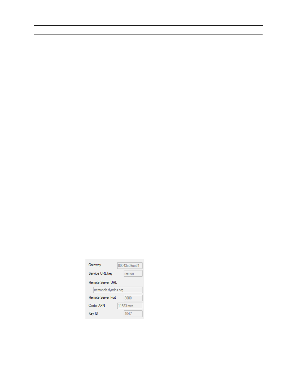
Also, the wireless settings that are programmed into
your site’s urlkey.dat file, are visible on the PCPatch
Settings screen.
All of these settings
must match the set-
tings in the FTP
receiving location in
order for wireless
transmission to take
place.
•Service URL key -
Your unique identi-
fier
•Remote Server URL- FTP Server’s fixed IP-address
or domain name.
•Remote Server Port - defaults to 21 or whatever is
required
•Carrier APN
•KEY ID - The receiving center identifier, which is
an ID for the actual unique 256-bit encryption key
for files sent via the Gateway/FTP.
If the data is incorrect or you do not have a urlkey.dat
file, contact NorthEast Monitoring or your distributor
for assistance.

NorthEast Monitoring, Inc. NEMM044-Rev-A Page 6 of 9
Gateway - FTP Technical Manual Chapter 4. Receiving Events via FTP
4. Receiving Events via FTP
System Requirements
The computer at the Service/institute where the events
are to be received, must have the following minimal
capabilities:
•Windows 10 or Windows 11 Operating System;
•Eight (8) GB of RAM memory;
•Twenty (20) GB of available disk storage;
•Broadband Internet connection
•Access to Port 21
•FTP server capability - Internal or commercially
hosted FTP site
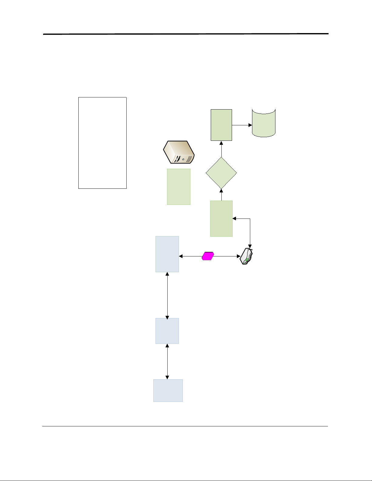
The Transmitting Process
1. The DR400 records an event
2. The DR400 is ready to send an event and attempts
to connect to the paired Gateway
3. If paired Gateway is found, the decrypted event is
transmitted via the wireless network
4. The FTP site receives two files for each event file
5. The Event Decoder utility that is running the back-
ground uses WinSCP to move the file to the local
PC and decrypts the file
6. The event file is placed in a designation location
where the LX Event Incoming screen can access it
7. User opens LX Event Incoming files screen and
assigns event to active patient.
The ETel Installer
The ETel utility must be installed on the local PC. The
Etel Installer includes 3 pieces of software that support
the Event process:
1. The Event Decoder - the Event Decoder runs in the
background and will restart when you reboot your
PC. The Event decoder calls WinSCP download the
event files from the FTP site, and then decrypts the
files using your unique urlkey.dat file, and places
the files into the Incoming Files folder for LX Event
to retrieve.
2. WinSCP, and FTP client, runs in the background.
The Event Decoder uses it to move the files from
the FTP site to the local PC.
3. The ETel utility is used for the MCT process. Once
an event procedure has been started, it can be used
to update settings, request MCT ECG data or to
view settings of the recorder.
Installing the Utilities
Contact Northeast Monitoring Support to get a copy of
the ETel installer Install the utility on a PC where the
LX Event software resides. By default, the installer will
create and be installed in the C:\nm\eventpgm directory.
The installer will put a shortcut in the startup list so it
will start on booting the computer. It assumes that
xx\ftp\event is the location where the "incoming files"
go and that the program will be in xx\eventpgm. Further
one has to put the urlkey.dat file in xx\eventpgm. xx\ is
by default c:\nm\
Note: You must put a copy of your urlkey.dat file into
the directory with the Event Decoder Utility in order
for it to run
FTP user name and password
Once the urlkey.dat file is in the directory, run event-
code with the argument “user password” to identify
your FTP site’s logon credentials. You will then need to
use these to set up the FTP site that you will be using to
transmit event.
To do this, open the Command prompt, go to
c:\nm\evenpgm and run:
c:\nm\eventpgm>eventdecode user password
Your response will look something like this:
NorthEast Monitoring EventDecode version 1.00
Jul 12 2021
service url: ABCDE
urlkey Key ID 1234
ftp server ftp.ftpnemon.com port 21
password AfRSD9eZ
The user name that you use to access your FTP site may
incorporate the user identified by the decoder utility,
and may not be the same exact string.

NorthEast Monitoring, Inc. NEMM044-Rev-A Page 7 of 9
Gateway - FTP Technical Manual Chapter 5. Set up and test the Process
5. Set up and test the Process
Before your first event procedure, you will need to set
up the system and then test to ensure that everything is
working correctly. We also recommend that you do a
quick test at the start of every procedure to ensure that
the DR400 and Gateway are communicating as
required.
Set up the system as follows:
1. Get a preconfigured urlkey.dat file, password and
username from NorthEast Monitoring.
2. Set up your FTP site using the username and pass-
word.
3. Install the PCPatch and copy the urlkey.dat file into
the installation directory. The default location is
c:\nm\bin.
4. Install the ETel utility, which includes WinSCP and
Event Decoder, and copy the urlkey.dat file into that
directory. The default location is c:\nm\eventpgm.
5. Install LX Event.
Test the set up:
1. Fully charge both the DR400 and Gateway.
2. Turn on the Gateway by holding down the button
for about 3 seconds. When the Gateway starts up,
you should see the battery indicator and the signal
strength on the screen. Ensure that the signal
strength has at least...
3. Using the docking station, attach the DR400 to the
PC via a USB port, and start the PC Patch utility.
4. On the PC Patch window, click on “Erase DR400”.
5. Use the PCPatch to pair the DR400 with the Gate-
way. Do this by going to the Settings screen clicking
on the “Pair Gateway” button. Once pairing is con-
firmed, compare the S/N on the Gateway with the
Gateway value in PC Patch.
6. While still on the Settings screen, confirm that the
DR400 recording mode is set to Event and the Event
settings are what you prefer. If using MCT, be sure
that MCT check time is not set to “20” or more.
Click “Update Recorder and Close” to save all of
the settings to the DR400.
7. On the main screen, enter the new Patient ID by
clicking on the “New patient” button.
8. Click on “Start DR400” and follow the prompts.
Once completed, remove the DR400 from the dock-
ing station. The DR400 starts flashing green at
startup.
Confirm set up by recording and sending
event
This process should be completed at the start of each
new procedure to ensure that the DR400 and Gateway
are paired and that events can be received.
1. If not running, start the ETel utility so that you can
verify that the files are downloading to your local
system.
2. With Gateway turned on and in room, create a man-
ual event by pressing the “Press” button on the
DR400. Once the green light stops flashing on the
DR400 (about 90 seconds), the recorder will attempt
to transmit the manual event.
3. After a minute, the ETel process will decrypt and
move the event file to the LX Event folder. Open the
LX Event utility and go to the Incoming Files win-
dow to view the file.
4. If you do not see a file in the Incoming Files win-
dow in LX Event, go to c:\nm\ftp\event to see the
event file is there. If it is there, the LX Event may be
looking for incoming files in a different location.
Troubleshooting
If the test did not work the first time, try transmitting
again by recording a second manual event. If the second
time does not work, there may be a problem, such as:
1. The DR400 has not started recording. If not record-
ing, you can start the DR400 by holding down the
“Press” button until the green light goes out and the
DR400 starts to flash.
2. The Gateway is not turned on. When turned on, you
should see the signal and battery levels on the
screen.
3. The Gateway signal is not strong enough. How does
the signal level appear on the Gateway?
4. The DR400 and the Gateway are not paired. If
paired, you should see the SN of the DR400, but
turning on/off the Gateway. Additionally, confirm
that the Gateway SN is on the DR400 by using the
PCPatch.
5. The FTP site is not set up properly

NorthEast Monitoring, Inc. NEMM044-Rev-A Page 8 of 9
Gateway - FTP Technical Manual Chapter 5. Set up and test the Process
6. You can also run a test. Record an event on the
DR400, and closely observe the screen on the Gate-
way. The number on the screen should change. If
there is no change, they Gateway and DR400 may
not be paired. If the number does change, call
NorthEast support for assistance.
7. Login to your FTP site to view the files. There will
be 2 files for each event. One file ends in “dat” and
the other “cmd”. (You may need to “refresh” to see
the files once they appear.) If they are there, the
event decoder may not be running. Contact North-
East support for assistance.
NorthEast Monitoring, Inc. NEMM044-Rev-A Page 9 of 9
9. Event Wireless Process Flow-chart
!!"
#$%()
*)
+,-
,
.,#/.,#0%)%
*%-1
*2(
3,4
5
1
6.,#
788 8824
!
"
#"$"
%"!!
"&
!"#
This manual suits for next models
1
Table of contents


