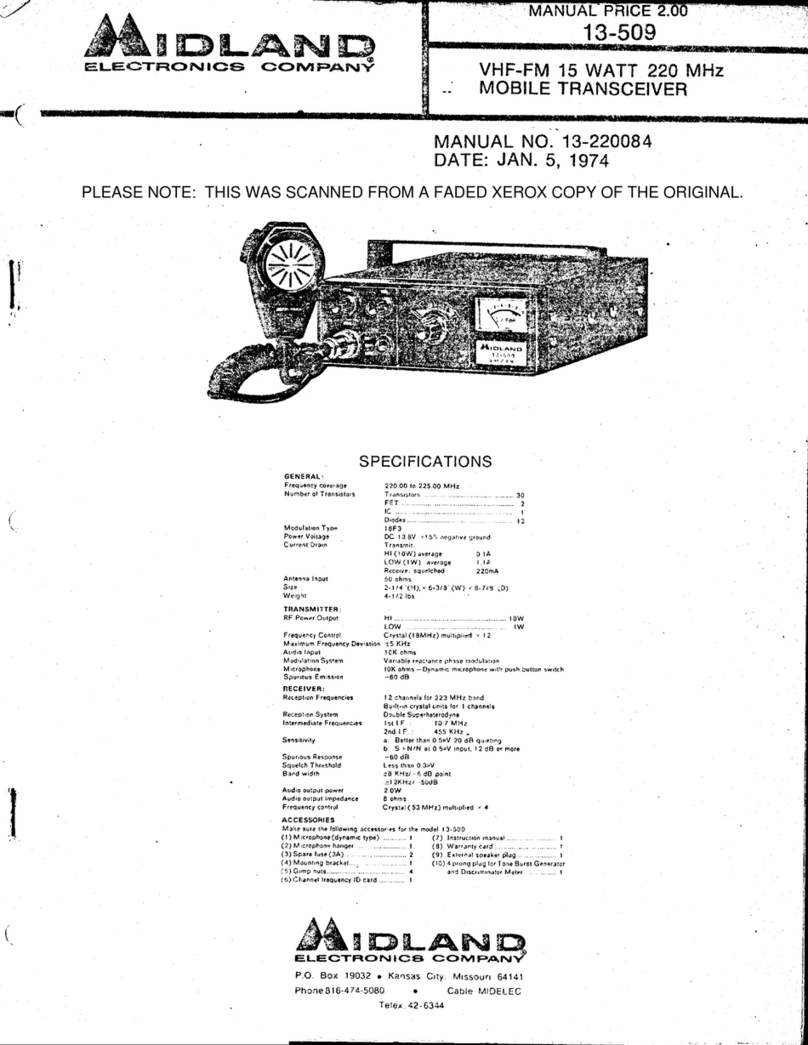
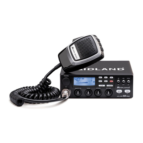
Midland 7001 User manual

OWNER’S MANUAL
40-channel single-sideband CB t ansceive .

P écision Sé iés™ 40-channel single-sideband
citizens band t ansceive .
For your protection, the spaces below are
provided for you to record the FCC Data and
Serial Number of this product. Both are
located on the identification plate attached to
the rear cabinet panel. fter recording these
numbers, keep this record for future
reference. When contaciing Midland for
service or parts information, the FCC Data
Number and Serial Number must be referred
to in order to expedite our request.
FCC D ata:
________________________________
Serial Num ber:
____________________________
Midland 7001

Welcome to the wo ld of
Midland P écision Sé iés
Single-Sideband CB.
Congratulations. You’ve just
graduated to the state of the art
in mobile CB privacy, power,
clarity and operating con-
venience.
major advance in the
history of personal communica
tions, single-sideband CB, in
effect, triples the number of
bands on which you can
communicate.
SSB splits each channel into
three (an upper and lower
sideband, in addition to
standard M), to give you the
greatest degree of privacy
available in CB.
In the years ahead, you can
expect to realize — time and
time again — the real reasons
and .meaning of the front-
running position Midland holds
among CBers everywhere.
nd you'll come to know
that Midland Power is more
than just a slogan, but the
heading of a long list of
seeable, hearable benefits.
Like Controls designed and
located for maximum
convenience and ease of
operation.
nd like the assurance that
comes from knowing the
nationwide Midland service
network goes with you
everywhere you take and use
your Midland SSB.
s your Midland SSB
experience unfolds and grows,
we hope you’ll remember that
CB radio is only one kind of
electronic excellence available
under the Midland nameplate.
Remember that the same
dependability, range and clarity
engineered into your SSB are
also built into a long, versatile
line of Midland car-stereo
receivers, tape players and
accessories.
Including widely-acclaimed,
exclusive Midland Micro-
Precision™ M/FM/MPX
electronic tuning. The one
that’s so microprecise, it seeks
out and locks exactly on the
station signal.
nd keep your eyes and
ears on the popular line of
Midland télévision sets. The
color and black-and-white sets
that give you the quality
features you want at some of
the most attractive prices in the
industry.

Contents
Midland 7001 features
______________
Pages 5-6
Installation Instructions
________________
Page 7
ccessories included
________________
Page 7
Location sélection
___________________
Page 7
Mechanical mounting
________________
Page 8
Power wiring
________________________
Page 8
Microphone hanger
_________________
Page 9
Optional remote speaker______________Page 9
Optional Public ddress Speaker
____
Page 9
ntennas
_____________________________
Page 10
Sélection (minimum requirements)
___
Page 10
Effect of location on performance
____
Page 10
Installation
_________________________
Page*1Q
Tuning
________________________________
Page 10
Operating instructions
_________________
Page 11
Operating Controls, connectors:
Functions and uses
______________
Pages 12-13
FCC requirements________________________Page 14
Forms included and how to use
_________
Page 14
General CB information
___________________
Page 14
Channel 9 usage_______________________Page 15
10-Code usage_________________________Page 15
■ Channel frequency chart
_
___________
Page 16
Range
________________________________
Page 16
Noise
_________________________________
Page 16
Trouble-shooting aids_____________________Page 17
Noise suppression______________________Page 17
Common problems and solutions (chart)Page 18
Technical spécifications
___________________
Page 18
Written spécifications
___________________
Page 18
Circuit diagram
______________
Pages 19-20-21
Service and Warranty information
__________
Page 22

Précision Sé iés™ 40-channel
single-sideband mobile
CB transceiver.
Midland 7001
Featu es:
Your new Midland mobile CB is
engineered to give you the most
convenient operation possible.
No other design aspect has been
given more attention than the time-
and motion-saving features built into
your new radio, microphone and
mounting system,
You’ll find and enjoy the benefits
of this attention to detail ail across the
control panel — including the panel
itself.
lso, all corners, knobs and other
protubérances are machine-radiused
to cushion impacts and prevent snags.
Not the cheapest way to finish.a
hardworking piece of equipment, but
we think it’s the best.
G een-colo LED digital channel
eadout. Green is the most easily seen
and readable color an electronic
display сап hâve. Gentle on your eyes
it focuses instantly to the eye, as
traditional red-color readouts can’t.
For added ease and convenience,
your Midland LED readout is coupled
with an analog numbered dial, to tell
you which way is “up" and which way
is “down” the channel spectrum.
High-visibility, black-on-light
g een mete s. Think about it. If white
letters on a black background were
easiest to read, ail newspapers,
magazines and books would be
printed that way — as are many other
CB meters on the market.
Midland meters are meant to be
seen and read. Instantly. So your new
Midland CB has a high-visibility black-
on-light green meter that won’t hâve
you squinting as you drive 55 miles an
hour down a sun-glaring or darkened
highway.
Exclusive beveled touch-cont ol
knobs. Your Squelch, F Gain, RF
Gain and other control knobs are
angled and notched. This way you can
control exact settings at a finger
touch.
In other words, you don’t hâve to
take your eyes off the road to make
corrections. You can do it quickly, just
by “feel.”
You’ll also note that ail your most
frequently-used Controls are located
on the driver’s side of the panel, for
quick, convenient access.
nd that the panel itself is
designed to prevent glare.
Human-enginee ed mic ophone.
The product of a long costly design
program, your new Midland CB mike
is shaped to specifically and precisely
fit the configuration of your hand.
Comfortable to hold, this design
makes Midland microphone operation
a natural, motion-saving convenience.
“Take-it-with-you” adjustable
mounting b acket. This design makes
it easy to mount and remove your new
CB for the safety and security of both
your car and radio.
The tilt/pivot adjustable feature
lets you position your CB at any angle
or height that’s most convenient and
comfortable for you.
к
Midland 7001 Mobile CB
Ope ating Cont ols. Dimme Switch.
Tone Switch
RF/Attenuation Switch
NB/ANL Switch
Cla ifie Cont ol
LSB/AM/USB Switch
S/RF Powe Mete . LED Digital Channel
Display.
Dual ed/g een TX/RX
(T ansmit/Receive) V
Indicato . \
AWI (Antenna Wa ning \
Indicato ) Light. у
4-pin/sc ew-typê
Mic ophone
Connecto .
Powe /AF (Audio
F equency) Gain
Cont ol. RF (Radio F equency)
Gain Cont ol.
CB/PA
Switch.
Va iable Squelch
Cont ol. Mic (Mic ophone)
Gain Cont ol.
Analog-numbe ed
Channel Selecto

How to install you
Midland mobile CB
This transceiver may be installée! in
any 12-volt negative o positive
g ound-system car or truck. Most
current U S. and foreign vehicles use a
negative system, but some older
models and some newer large trucks
may hâve a positive ground.
Check the equi ements fo you
vehicle betö e you begin installation.
. Generally, you hâve a negative-
g ound system if the minus (-) battery
terminal is connected to the motor
block. Contact your dealer in the event
you are unable to détermine your
vehicle’s polarity system,
Installation and ope ating
accesso ies fu nished with
you Midland Mobile CB:
1. “Take-it-with-you” adjustable
mounting bracket system.
2. Microphone bracket system.
3. ll main-unit and microphone
mounting hardware needed for
normal installation.
4. DC power cord with plug.
5. Plug-in microphone with coil cord.
6. FCC Form 505
7. FCC Part 95, Subpart D.
8. FCC Form 555-B.
9. Owner's Manual.
10. Customer Registration Card.
Whe e to locate you CB
t ansceive .
Your new Midland CB is designed
to be installed under the dash of your
vehicle.
Safety and convenience are the
primary considérations in deciding
exactly where to locate your radio.
The transceiver is designed with
most-often-used Controls nearest the
driver. Still, make sure other Controls
are easily reached
Caution: Be su e that the unit is
located so that it does not inte fè e
with the d ive o impai access to any
Cont ols. Connecting cables must be
outed and secu ed in such a manne
as to not inte fè e with the ope ation
of the b ake, accele ato o othe
Cont ols. Inte fé ence f om eithe the
unit o connecting cables may
cont ibute to the loss of cont ol of the
vehicle.
7

Mechanical mounting.
Step 1: Heeding the preceding caution,
use the mounting bracket as a
temptate for marking the location of
screwholes under your dash. Use an
awl, nail or other pointed object to
mark the metal.
Step 2: Drill a 1/8" hole for each
screwhole in the mounting bracket.
ttach the bracket to the dash with the
3/8" Phillips machine screws provided
Ext eme caution should be exe cised
when d illing into dash to avoid
damage to unde -dash elect onic
ignition, c uise cont ol, inst ument
and/o accesso y wi ing.
Step 3: ttach removable 3-pm, piug-
in DC cord to 3-pin polarized DC jack
on the rear of the transceiver.
Step 4: Locate and secure the radio
into the mounting bracket, allowing
working space for later power
connections.
Powe wi ing.
Step 1: If you have not determined
whether your vehicle has a negative or
positive ground, do so now.
Then disconnect the leads from
the battery to prevent short circuits
that сап occur during wiring.
Step 2: With negative g ound, connect
the red wire — the one with in-line
fuse holder — to either the (a) fuse
block, (b) cigarette lighter or (c)
directly to the positive post on your
battery.
(Usually, the fuse block is the
most convenient connecting point. It is
also possible to connect to the
ccessory terminal on the fuse block
or ignition switch, so that your CB
automatically goes off when the
ignition goes off, preventing accidentai
battery drainage.)
Then tightly connect the black
wire directly to the vehicle’s metal
frame.
With a positive g ound, reverse the
wires, connecting the red/fuse-holder
wire to the frame, the black wire to
your DC power source. light or
meter can be a good aid in locating a
suitable power source and ground.
In either case, a good, direct
metal-to-metal ground is essential for
optimum performance.
CAR S MOTOR BLOCK OR FIRE WALL GROUND
SOLENOID
ex am ple of
NEG GROUND 12-V DC C R ВАТТ
CONNECTION ILLUSTR TION
MOST C RS & TRUCKS RE
THIS TYPE
POSITIVE SOLENOID
POS GROUND 12 V DC C R ВАТТ
CONNECTION ILLUSTR TION FEW
18 WHEELERS Ä OLDEP C RS
8

Mounting the main unit.
Step 1: Loosen the retaining knobs on
each side of the mounting bracket to
give enough space for the unit to slide
between the two bracket arms.
Step 2: Position the main unit between
the bracket arms in line with the
retaining knobs. Set the height and
angle for optimum operating comfort
and accessibility.
Step 3: Tighten the retaining knobs.
Installation of mic ophone
hange .
Mounting holes are provided on
the side of the transceiver for the
microphone hanger bracket.
lternately, the bracket can be
attached to the vehicle dash.
Connecting optional emote
speake .
Locate the “EXT” jack on the
main unit rear panel. Firmly insert and
seat the speaker wire plug into the
jack.When connected, the externa!
speaker will override and “blank out”
the in-unit speaker standard with your
Midland Mobile CB.
Connecting optional Public
Add ess speake .
Locate the “P ” jack on the main
unit back panel. Firmly insert and
seat the speaker wire plug into the
jack.Directions for mounting the
optional Public ddress speaker are
included, along with mounting
hardware, with the speaker.
9

Antennas: How to select,
position, install and tune
the ight one fo you.
Basically, you hâve two types of
mobile CB antennas -- fulI-length
whtp and loaded whip — and a variety
of types of mounts (depending on
where you locate your antenna) to
choose from.
Midland markets a broad linę of
high-performance antennas. The
dealer who sold you your Midland CB
can advise which type is best for you.
Essentially, you hâve five location
choices; the roof, gutter, rear deck,
front cowl or reai buc per
Where you décidé to locate your
antenna will determme the type of
antenna you install. gain, consult
your Midland CB Dealer for advice and
guidance, and measure your rieeds
against the attribufes of the varions
Midland antenna models he car ries.
Whe e you locate you antenna
does make a diffé ence.
Sonie general rules for antenna
location thaï can aid CB performance:
1. Put your mount as high on the
vehicle as possible.
2. The higher the proportion of
antenna length that is above the
roof, the better.
3. If possible, mount the antenna in
the center of whatever surface you
choose.
4. Keep antenna cables away from
noise sources, such as ignition
system, gauges, etc.
5. Make sure you hâve a solid metal-
to-metal ground.
6. Exercise care to prevent cable
damage.
Antenna installation.
Follow the manufacturer‘s
installation instructions carefully.
Wa ning: Neve ope ate you CB
adio without attaching an antenna o
with a b oken antenna cable. This can
esuit in damage to t ansmitte
ci cuit y.
Tuning you antenna.
Some antennas are factory tuned.
However, performance can usualiy be
improved by siightly lengthening or
shortemng its length, using a Standing
Wave Ratio (SWR) meter. For the exact
procedures to be used, refer to the
antenna manufacturer’s installation
manuał.
You can buy an SWR meter
separately or hâve your antenna
checked by your Midland CB Dealer's
service department.
i
:Rea
10

Midland 7001:
Ope ating Inst uctions
Having p ope ly installée! and
wi ed you CB and antenna, you a e
now eady fo the eight steps
designed to get you mto effective,
satisfacto y ope ation:
Step 1: Inse t the plug f om the
mic ophone into the mic ophone jack
on the side panel, and sc ew on
Step 2: Make su e you antenna is
secu ely connected to the antenna
connecto ..
S Q U E LC H
M
Step 5: Select the desi ed mode of
ope ation, USB, AM o LSB, using the
selecto switch.
Step 6: Tu n the powe on and adjust
the Audio F equency (AF) Gain
Cont ol fo a satisfacto y sound level.
Step 7: Select you desi ed channel by
tu ning the Channel Selecto dial
below the LED digital indicato .
Step 3: Make su e the Squelch Cont ol
is in the 9:00 position.
Step 4: Make su e the RF Gain Cont ol
is fully clockwise.
Step 8: To t ansmit, p ess the push-to-
talk ba on the mic ophone. To
eceive, elease the ba .
11

Ope ating Cont ols,
connecto s: Thei
functions and uses.
Ste ling at the uppe left (d ive ’s side)
and moving counte -clockwise:
5/RF Powe Mete . This new high-visibility,
btack-on-light g een mete is used two
ways. (1) When eceiving, it gives the
elative st ength of incoming signais. (2)
When t ansmitting, it shows RF (Radio
F equency) powe output.
4-pin/sc ew-type Mic ophone Connecto .
Secu ely links you mic ophone to the main
unit du ing use, yet allows quick
disconnection when out of se vice.
Off/AF Gain Cont ol. Tu ns you CB on and
adjusts the Audio F equency (volume) level
for comfo table éception.
Squelch Cont ol. Tu ned clockwise, it
quiets the eceive when signais a e not
being eceived and allows a quiet standby
ope ation.
The Squelch Cont ol functions only in
the eceive mode and does not affect
eceive volume when signais a e being
eceived.
To adjust, when no signais a e p esent,
otate the Squelch Cont ol clockwise until
the eceive is quieted. Incoming signais
will automatically elease the squelch
actign.
Ca eful adjustment is necessa y as a
setting too fa clockwise will not allow
weake signais to elease the squelch
action.
LED Digital Channel Display. Illuminated in
easy-to- ead g een, it displays the channel
selected by use of the analog-numbe ed
dial just below.
RF (Radio F equency) Gain Cont ol.
Cont ols the éception sensitivity ( ange) of
you CB. To dec ease RF gain — to educe
inte fé ence, fo example, in congested
u ban a eas — tu n the knob counte -
clockwise; to inc ease tu n clockwise. The
RF Gain Cont ol affects éception only. It
will not affect t ansmitte output powe .
Cla ifie Cont ol. “Fine-tunes” signais
eceived on eithe the uppe o lowe
sideband.
LSB-AM-USB Mode Selecto Switch.
Selects the mode of t ansmission and
éception. Eithe the uppe sideband o
lowe sideband of a channel can be
selected, o conventional AM ope ation.
Mic (Mic ophone) Gain Cont ol. Adjusts the
sensitivity of the mic ophone amplifie
ci cuit to suit individual voice
cha acte istics and ambient noise
conditions to p ovide maximum
intelligibility. Rotating the cont ol counte -
clockwise educes the sensitivity and
equi es “close-talking” into the
12

microphone. When operating from a noisy
vehicle, reducing the Mic Gain setting will
usually improve your transmitted voice
clarity. Check with other operators to
détermine the exact setting best for your
voice and car.
CB/РА Switch. n optional P speaker may
be attached to your transceiver through the
P output jack on the back panel. This
allows you to communicate with
pedestrians or other vehicles through your
CB microphone. The CB/РА switch
changes your CB speaker system from a
CB function, using the internai main-unit
speaker, or optional external speaker, to a
Public ddress function.
Dimme Switch. Dims or brightens lighted
Controls for more comfortable day or mght
visibility.
Tone Switch. Controls the tonal quality of
received signais in accordance with the
user’s preference.
NB/ANLSwitch. In the NB (Noise
Blanker) & NL ( utomatic Noise Limiter)
setting, it reduces electrical impulse
noises, such as those caused by engine
ignition Systems, atmospheric noise and
other electrical interférence. The "Off”
setting is used when neither problem existe.
RF Attenuation Switch. Reduces the
incoming signal strength before reaching
the sensitive receiver circuits. Use the “on”
position to improve receiver cross-
modulation and blocking performance in
strong signal metropolitan and urban areas.
Dual ed/g een TX/RX Indicato . When red,
it indicates the unit is transmitting and acts
as a warning when the microphone push-
to-talk bar is accidentally keyed. When
green, it indicates your transceiver is in the
“receive” mode.
AWI (Antenna Wa ning Indicato ). lerts
you to trouble in your antenna system that
could damage your transceiver. When the
WI light cornes on, you should stop
transmitting immediately.
Exte nal Speake Jack. llows you to
attach an external speaker that will override
the unit’s internai speaker. Connection is
made through the External Speaker Jack
on the back panel.
PA Jack. n optional P speaker may be
attached to your transceiver through the P
output jack on the back panel. This allows
you to communicate with pedestrians or
other vehicles through your CB
microphone.
Mic ophone Push-to-Talk Ba . Simply push
this bar to transmit; release when receiving.
13

FCC equi ements
fo CB use s.
Your new Midland Mobile CB is a
combination receiver/transmitter
(transceiver) designed and built for
licensed Class D operation on any of
the 40 frequencies designated for
citizens band use by the Federal
Communications Commission.
You are required to have or have
ordered a current сору of Part 95,
Subpart D, of the FCC rules and
régulations (a current сору as of the
date of manufacture is included with
your new CB) prior to operation of
this unit.
You are also required to complété
FCC Form 505 (also included with
your CB) and submit it to the FCC,
Gettysbu g, PA 17326 in order to
obtain your license to operate this
unit.(Disregard the above paragraph if
you have a current CB license less
than 5 years old.)
FCC régulations will be violated if
you transmit with this unit without
complying with procedures explained
on FCC temporary license, Form 555-
B, which is included as well.
You may use Form 555-B as a
temporary permit while your regulär
Form 505 application is being
processed by the FCC.
The technical information,
diagrams and charts provided in this
manuał are supplied for the use of a
qualified holder of a first or second
class radio-telephone license. It is the
user’s responsibility to see that this
unit is operating at all times in
accordance with FCC Citizens Band
Radio Service régulations.
If you install your own transceiver,
do not attempt to make any transmitter
or receiver tuning adjustments. These
adjustments are prohibited by the FCC
unless you hold a first or second class
radio-telephone license. Citizens
Band or mateur license is not
sufficient.
When service is performed by an
authorized and licensed person, care
must be taken that only authorized
replacement parts are used in order
to not void the type acceptance or
certification of this model.
Midland International Corporation
hereby certifies that this unit has been
designed, manufactured, FCC type
accepted and certified in accordance
with Part 95 and Part 15, Subpart C, of
the current FCC rules and régulations
as of the date of manufacture.
Gene al CB
info mation.
In 1958, The Federal
Communications Commission
approved the use of 23 Channels by
duly licensed Citizens Band radio
operators. The authorization was
expanded to 40 channels in 1977.
simple, basie means of
communication, CB requires no more
ski11 or knowledge than the operation
of a Standard M or FM receiver.
Still, there are certain tacts,
procedures and “rules of the road”
you’ll need to know in order to make
the naost of your CB expérience.
Make it “sho t and sweet.” When
using your CB, get on and off the air
as quickly as possible. Never use
profanity — which is against the law
and subject to heavy penalties. Follow
the FCC rules outlined in Part 95.
Use Channel 9 in eme gencies
only. Emergency channel 9 is
designated for this purpose and this
purpose alone.
The FCC has given public safety
agencies various “call signs” including
“0911“ numbers, coinciding with the
“911” phone numbers these agencies
use in téléphoné communications.
The call signs for state-level
agencies use 3 letters and 4 numbers,
with the second and third letters being
the official Post Office state
abbreviation, e.g., “KS” for “Kansas.”
Why and how to use the “10
Code.” Developed over the years by
official agencies in order to save time
and provide précisé, elear messages,
the “10-Code” has become a popular
tool for CBers.
14

The table below lists some of the morę
common codes and their meanings.
Code Meaning 10-35 Confidential information.
10-1 Receiving poorly. 10-36 Correct time is.
10-2 Receiving well. 10-37 Wrecker needed at.
10-3 Stop transmitting. 10-38 mbulance needed at.
10-4 OK, message received. 10-39 Your message delivered.
10-5 Relay message. 10-41 Please turn to Channel.
10-6 Busy, stand by. 10-42 Traffic accident at
10-7 Out of service; leaving the air. 10-43 Traffic tie-up at.
10-8 In service, subject to call. 10-44 I hâve a message for you.
10-9 Repeat message. 10-45 il units within range report.
10-10 Transmission completed, standing 10-50 Break channel.
by. 10-60 What is next message number?
10-11 Talking too fast. 10-62 Unable to сору; use phone.
10-12 Visitors present. 10-63 Network directed to.
10-13 dvise weather/road conditions. 10-64 Network elear.
10-16 Make pickup at. 10-65 waiting your next message/
10-17 Urgent business. assignment.
10-18 nything for us? 10-67 ll units comply.
10-19 Nothing for you; return to base. 10-70 Fire at.
10-20 My location is. 10-71 Proceed with transmission in
10-21 Call by téléphoné. »sequence.
10-22 Report in person to. 10-77 Negative contact.
10-23 Stand by. 10-81 Reserve hotel room at.
10-24 Completed last assignment. 10-82 Reserve room for.
10-25 Сап you contact? 10-84 My téléphoné number is.
10-26 Disregard last information. 10-85 My address is.
10-27 I am moving to Channel. 10-91 Talk doser to mike.
10-28 Identify your station. 10-93 Check my frequency on this
10-29 Time is up for contact. channel.
10-30 Does not conform to FCC rules. 10-94 Please give me a long count.
10-32 I will give you a radio check. 10-99 Mission completed; ail units
10-33 Emergency traffic. secure.
10-34 Trouble at this station. 10-200 Police needed at.
Musts and mustn’ts
of CB usage.
You must identify your official licensed
cali sign at the finish of every
conversation.
You mustn’t carry on a conversation
with another station for more than 5
minutes at a time without taking a 1-
minute break, to give others use of the
channel.
You mustn’t blast others off the air by
overpowering them with illegal
transmitter power or iIlegally high
antennas.
You mustn’t use CB to promote illegal
activities.
You mustn’t use profanity.
You mustn’t play musie on your CB.
You mustn’t use your CB to sell
merchandise or commercial services.

F equency-channel
numbe cha t.
Frequency Channel
26.965 MHz .... 1
26.975 MHz 2
26.985 MHz 3
27.005 MHz 4
27.015 MHz 5
27.025 MHz 6
27.035 MHz _ _ _. 7
27.055 MHz 8
27.065 MHz _. _ 9
27.075 MHz 10
27.085 MHz 11
27.105 MHz 12
27.115 MHz 13
27.125 MHz .. ... .. . 14
27.135 MHz _ 15
27.155 MHz 16
27.165 MHz 17
27.175 MHz 18
27.185 MHz 19
27.205 MHz
......
20
27.215 MHz . 21
27.225 MHz 22
27.255 MHz 23
27.235 MHz _. 24
27.245 MHz 25
27.265 MHz
__
26
• 27.275 MHz 27
27.285 MHz 28
27.295 MHz 29
27.305 MHz 30
27.315 MHz 31
27.325 MHz _ 32
27.335 MHz 33
27.345 MHz. 34
27.355 MHz 35
27.365 MHz 36
27.375 MHz 37
27.385 MHz 38
27.395 MHz 39
27.405 MHz 40
Facto s affecting
effective CB ange.
Essential ly, they’re the same
influences that optimize or limit M,
FM and other kinds of performance in
moving vehicles:
Te ain: Hills and valleys naturally
interrupt and shorten CB signais.
Weathe . You can expect that CB
range will be reduced — perhaps
drasticajly — in times of atmospheric
disturbance, such as in a thunderstorm
or heavy snow. Sunspots, too, are
known to adversely affect CB
performance.
Obst uctions. Inside a tunnel,
covered parking garage or viaduct, CB
transmitting/receiving capability may
be eut off altogether.
In short, you can expect to
maintain maximum transmitting/
receiving performance in flat, open
country in stable (not necessarily
elear) weather conditions.
Should effective range be limited
in these conditions, check to see that
your CB is connected properly and
your antenna adjusted correctly. It
may be necessary to consult your
Midland CB Dealer’s service
department.
What causes noise?
If you hâve an abnormal noise
problem, the chances are your vehicle
itself is the cause.
CB receiver is a very sensitive
instrument, abîe to pick up small noise
signais and amplify them —
particularly if the source of these
signais is within a few feet of your CB.
ny noise that cornes from your
CB almost certainly cornes from '
outside the unit itself. Devices hâve
been designed into your Midland CB
(a noise blanker or an automatic noise
limiter, for example) to minimize this
kind of distraction.
T ouble-shooting aids.
Frequently, there are simple, quick
actions you can take to eliminate or
minimize such problems as
interférence and noise.

Noise supp ession.
very common source of
excessive noise is the ignition system
of a CB owner's vehicle. If you suspect
this is true, simply turn off the ignition
and set the key in the accessories
( CC) position.
This way you’ll provide power to
the transceiver, minus any ignition
interférence that might exist. If the
noise goes away, you know instantly
that the ignition system is the culprit.
Still, there are a number of places
in the ignition system where noise can
originate.
Spa kplugs and sparkplug wires
are probably the worst noise
producers. To eliminate this kind of
noise, you can fake any of four simple
measures: (1) Install résistive
sparkplug suppressors, (2) resistor
sparkplugs or (3) resistance-wire
cabling, between plugs and the
distributor and also between the
distributor and ignition coil. (4)
Replace old plugs and sparkplug
wiring and properly tune the engine.
This generally cures most noise.
Many cars corne suppressor-cable
equipped. If yours didn’t (consult your
vehicle owners manuał or dealer
service department to be sure), you
can get it at any auto supply store
and, given a moderate amount of
mechanical ski11, install it yourself.
Caution: Do not unde take any
ignition-system epai s o
modifications without eithe
P ofessional help o some automotive
se vice expé ience.
Gene ato -b ush spa king can
create an annoying “whine.” It’s
caused by a dirty commutator, and is
eliminated by polishing its surface with
fine-grade emery cloth, and cleaning
grooves with a small, sharp tool.
Voltage egulato s can cause a
“hashy” sound in your CB when relay
contacts jitter open and closed when
the battery is fully charged. To
eliminate this noise, mount coaxial
feedthrough capacitors at the battery
and armature terminais on the
regulator box.
Alte nato slip rings should also
be kept clean and good brush contact
maintained to minimize CB noise.
In addition, single-contact
alternator regulator boxes need a
coaxial capacitor at the ignition
terminal. Double-contact units should
hâve a second capacitor at the battery
terminal. Shielding between the
regulator and alternator may be
needed as well. Be sure to ground the
shield at both ends.
Infrequent, though real, noise
generators like your car’s heater fan,
turn signais, electric Windows and
windshield-wiper motors can also be
silenced with a coaxial capacitor
(consult your serviceman).
Wheels and ti es can also cause
CB noise. Wheel noise is eliminated by
putting static-collector springs
between the wheel spindle boit and
grease retainer cup. Tire static can be
quieted with antistatic powder applied
inside each wheel.
Antenna co ona-discha ge noise
— most frequently occurring with
sharp-pointed “whip” models — can
happen just before or during electrical
storms.»The only cure is for the storm
to blow over or pass

SOLUTIONS.
'I JS
JS
rv
ß 1 i f f ß t л I Jt,
No sound o channel light. •••• 1
Channel light but no sound. •••• • •
No voice éception. •••
Poo éception. •• • •
T ansmission p oblems. • • • • •
Unclea éception. •• • 1 •
Poo PA Audio F equency. •
Inope ative channel seiecto . •T
Caution: The 2-amp fuse included with this unit is an impo tant safety teatu e which must not be
ci cumvented. Removal of this fuse o the use of a fuse g eate than 2 amps may esuit in ove heating and/o
fi e and consequential damage to the unit o vehicle. If a eplacement 2-amp fuse bu ns oui, hâve the unit
inspected and epai ed by a qualified se vice technicien.
Midland 7001 Mobile CB T ansceive : Technical Spécifications.
Gene al Const uction.
1 Three-pin polanzed iack tor DC power
2 Four-pin screw connector for microphone.
3. No mechanical relays il switchmg is
solid state using diodes and transistors
for high reliability.
4. Transmitter output stage is protected
from mismatch, no-load or short-circuit
conditions
5. Input power is suitably filtered and
bypassed to deter alternator whme on
transmit or receive
Elect ical Spécifications.
Gene al:
Voltage
.....................
13 8 V, Positive■
Negative Ground
Operating Range:
10 V to 16 V
Frequency Stability.. .1.005%
Température Range.. -30° to + 59°C
(Per FCC Part 15)
Humidity
.................
5-90%
Vibration
.................
EI Standard RS-424,
Shock
......................
EI Standard RS-424
Receive (AM):
Sensitrvity.
Less than 0 7 uv for 10 dB SN *N to N
utomatic Gain Control Figure of Merit
80 dB
udio Squelch Sensitivity
Threshold Less than 10 cB SN*N to N.
Tighl: 100 uv minimum. 500 uv
maximum
djacent Channel Seiectivity and
Desensitization
60 dB (Two-generator method)
Spurious Response ttenuation
60 dB (excluding image at 50 dB)
udio Power Output
3 W (® 10% distortion (load impédance
8 ohms résistive)
udio Frequency Response (1 KHz 0 äB
reference)
300 Hz (в; 5 dB.
1000 Hz C* 0 dB
2000 Hz Co) -3 dB
Hum and Norse. Squelched
45 dB
Noise Limiting
Provided with Switchaßle NL
S Meter Sensitivity at S 9
100 uv
RF Gain Range
30 dB
ntenne Input Impédance
50 ohms, unbalanced
T ansmitte (AM):
Carrier Power. No Modulation
4 W maximum. 3 6 minimum
Conducled Spurious Emissions
65 dB
Radiated Spurious Emissions.
(Compiles with FCC Part 95)
udio Frequency Harmonie Distortion
10% maximum («i 80%
udio Frequency Response (1 KHz, 0 dB
reference)
300 Hz ę> -5 dB.
1000 Hz (S) 0 dB
3000 Hz Co; 6 dB
Hum and Noise.
40 dB
Output Impédance
50 ohms, unbalanced
Output Protection.
Withstands tor b minutes alt VSWR
around Smith Chart at 20:1 without
damage oi failure
Output Stability
Does not exceed FCC Limits For
Spurious Emissions when operated
into a mismatch load with 5 1 VSWR at
any point on the Smith Chart
Cont ols: Off F gain control. Squelch
control RF gain control Microphone
Gam control. CB P switch Hl/Lo
Tone switch NB- NL-Off switch.
S/RF/PWR Meier Green color
Numerical LED Channel indicator
Rotary nalog-Numeral Channel
seiector
Jacks and Connections: 4-pin/screw type
Microphone Connector. 50-ohm
antenna. 8-ohm externat speaker, P
speaker
Accesso ies Included: 500-ohm push to-talk
microphone with coil cord and screw-
on. 4-pin connector. Microphone clip
Mounting bracket and hardware.
Owners manuał FCC forms 505.
555-В. Part 95

PällS Layout. Main PC Boa d.
.0:4:% '•'V <T|p^:'+';.vi
-Vе' '.V* t ! Pf
^o,rrf^.
Ï^ b '.:'> d)
Ирик WbJ» ■
Component slde.
19

Pa ts Layout. Main PC Boa d
*tar
vjjjtr*
, Kitj.
’-'ftr*
I m i i
Patte n side.
Other manuals for 7001
2
Table of contents
Other Midland Transceiver manuals

Midland
Midland G15 Manual

Midland
Midland 777 PRO User manual

Midland
Midland M Zero Plus Manual

Midland
Midland ALAN 42 MULTI User manual

Midland
Midland Alan 78 Plus Multi B User manual

Midland
Midland Alan 52 Multi Manual

Midland
Midland CT 710 Manual

Midland
Midland G14 Manual

Midland
Midland G-11 Manual

Midland
Midland 88 User manual

Midland
Midland CT 890 User manual

Midland
Midland PACIFIC User manual

Midland
Midland 77-092 User manual

Midland
Midland CT 890 Manual

Midland
Midland 202M User manual

Midland
Midland G10 PRO Manual

Midland
Midland M24-S User manual

Midland
Midland G5 User manual

Midland
Midland 73-005 User manual

Midland
Midland ALAN 54 E User manual